Table of Contents
Advertisement
Available languages
Available languages
Owner's Manual
I CRRFTSMRH°I
Lawn Utility Vehicle
Model No.
247,270250
CAUTION:
Before
using this product,
read this manual and
follow all safety rules
and operating
instructions.
•
Safety
•
Operation
•
Maintenance
•
Storage
•
Espanbl
Sears, Roebuck And Co., Hoffman Estates, IL 60179 U.S.A.
Visit our website: www.sears.com/craftsman
FORM NO. 769-00054
Printed in U.S.A.
(2/2002)
Advertisement
Table of Contents

Related Manuals for Craftsman 247


Summary of Contents for Craftsman 247
- Page 1 247,270250 CAUTION: Before using this product, read this manual and follow all safety rules and operating instructions. Sears, Roebuck And Co., Hoffman Estates, IL 60179 U.S.A. Visit our website: www.sears.com/craftsman Printed in U.S.A. • Safety • Operation • Maintenance •...
- Page 2 Operation Maintenance LIMITED WARRANTY ON LAWN UTILITY VEHICLE: For two (2) years from the date of purchase, if this Craftsman Riding Equipment is maintained, lubricated and tuned up according to the instructions in the owner's manual, Sears will repair or replace free of charge any parts that are found to be defective in material or workmanship coverage listed below.
- Page 3 WARNING: This symbol points out important safety instructionswhich, if not followed, could endanger the personal safety and/or property of yourself and others. Read and follow all instructions in this manual before attempting to operate this machine. Failure to comply with these instructions may result in personal injury.
- Page 4 26. Use only accesaories and attachments approved for this machine by the machine manufacturer. Read, understand and follow all instructions provided with the accessory or attachment. 27. Data indicates that operators, age 60 years and above, are involved in a large percentage of tractor-relsted injuries.
- Page 5 e. Extinguish all cigarettes, cigars, pipes and other sources of ignition. Never fuel machine indoors. Never remove gas cap or add fuel while the engine is hot or running. Allow engine to cool at least two minutes before refueling. Never over fill fuel tank. Fill tank to no more than ½...
- Page 6 WARNING: feet). A lawn utility vehicle could overturn and cause serious injury. Operate these vehicles up and down slopes, never Do not mow on inclines with a slope in excess of 15 degrees (a rise of approximately 2.5 feet every 10 across the face of slopes.
- Page 7 Unpacking Unit Remove all screws and staples from the crete. Holding sides of the crete firmly, lift top of the crate up and set itaside. Avoid tire punctures. Remove and discard plastic bag covering the unit. Lift the rear of the vehicle off the crate. Repeat for the front.
- Page 8 Figure 3 NOTE: The grass bag must be in position, on the vehicle, for any kind of mowing operation, including mulching and side-discharge of grass clippings. Attaching Grass Catcher The grass catcher is assembled at the factory and attached to the vehicle for shipping convenience. The grass catcher has to be attached to the vehicle only when cuffing grass and/or bagging the grass clippings.
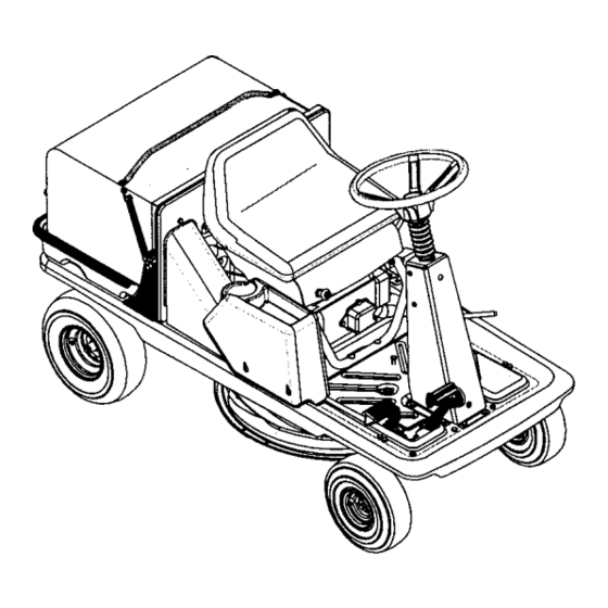
- Page 9 Know Your Lawn Utility Vehicle The Lawn Utility Vehicle is meant to be used as both a riding lawn mower and a utility cart. Its grass collector can be easily removed to expose the utility bed. Compare the illustrations in Figure 7 with your lawn utilityvehicle to learn about the location and features of its vadous controls.
- Page 10 ShiR Lever This lever is located on the left side of the fender and has three clearly marked positions: FORWARD (F), REVERSE (R) and NEUTRAL (N). Follow the label on the unit to place the shift lever in the position desired. IMPORTANT:The brake pedal must be depressed completely and the vehicle not in motion while sliding the shift lever...
- Page 11 If the level is short of that, add oil to the oil fill slowly. Recheck the oil level on the dipstick. If needed, add more oil. Do not overfill. NOTE: The lawn utility vehicle is shipped with oil in the engine crankcase. Place the dipstick in position and tighten to secure.
- Page 12 NOTE: Do not hold the key in the START position for longer than ten seconds at a time. Doing so may cause damage to your vehicle engine's electric starter. After the engine starts, press choke control inward, thus closing the choke. See Figure 8. NOTE: Do not leave the choke control...
- Page 13 Using as Utility Cart The lawn utility vehicle, as its name suggests, can be used as both a riding lawn mower and a utility cart. Remove grass catcher to expose the utility bed.
- Page 14 These may cause damage to electrical components, spindles, pulleys, beadngs or the engine. The use of water may shorten life of your lawn utility vehicle and reduce its serviceability. • Follow the schedule below to ensure best performance by your lawn utilityvehicle.
- Page 15 Changing The engine on your lawn utility vehicle has an oval air cleaner cartridge and a pre-cleaner. See engine parts list starting on page 37 of this manual for the part numbers.
- Page 16 Completely loosen the two screws that hold the cover of the air cleaner. Remove the entire air cleaner assembly from the base. Liftthe cover off the air cleaner. See Figure 13. Base Figure 13 To clean cartridge, gently tap pleated paper side on a flat surface.
- Page 17 Set the parking brake and push the vehicle. Ifthe rear wheels roll, adjust the brake following instructions on page 20. Tires air pressure shown on sidewall of the tire. ARNING: Never exceed maximum limit of The recommended operating tire pressure is 20-22 psi for both sets of tires.
- Page 18 Then proceed with the adjustment. Adjusting Seat Position The seat position on the lawn utility vehicle can be adjusted to maximize the operator's convenience. Stop the vehicle completely and engage the parking brake. Tum ignition off.
- Page 19 Retighten jam nuts when proper tension is reached. Test the adjustment. Readjust if necessary. Jam Nut Deck Engagement Cable Figure 19 Adjusting Speed Control Rod This adjustment is necessary when the vehicle cannot hold the full range of speeds, or shows belt drag (=creep")when the drive pedal is released.
- Page 20 Adjusting Brake WARNING: Do not adjust the brake while engine is running. Be sure to block the wheels of the vehicle before attempting any adjustment on the brake cable. NOTE: Adjustments are done at the cable end; for adjustment of the calipers, see a Sears service center. IMPORTANT:The brake cable should be adjusted so that it has a bit of slack when the brake is released.
- Page 21 IMPORTANT:When either or both of the drive belts are worn off, replace both. Replacing only one willaffect the performance of your lawn utility vehicle. NOTE: It may be necessary to adjust the speed control linkage after replacing both drive belts.
- Page 22 Remove the upper drive belt first by working from the back of the unit. Roll the belt off the idler pulley first and then off the transmission pulley. Next roll it off the variable speed pulley. Working from the side of the unit, pull the lower drive belt tension pulley to the right and roll the lower drive belt off this pulley.
- Page 23 If the lawn utility vehicle is to be inoperative for a period longer than 30 days, follow the steps below for storage. Preparing for Storage Battery Fully charge the battery with a 6 amp battery charger. NEVER store battery without a full charge.
- Page 24 Trouble Engine f ails tostart Blade control lever engaged. Parking brake not engaged. Spark plug wire(s) disconnected. Choke not activated Fuel tank empty, or stale fuel. Blocked fuel line. Faulty spark plug. Engine runs erratic Unit running with CHOKE applied. Spark plug wire loose.
- Page 25 Parts List for Craftsman Lawn Utility Vehicle Model 247.270250 NOTE: For painted parts, please refer to the list of color codes below. Please add the applicable color code, wher- ever needed, to the part numbar to order a replacement part.
- Page 26 Parts List for Craftsman Lawn Utility Vehicle Description Key No. Part No. 731-1687 Steedng Wheel 731-t459A Steering Wheel Cap 647-0055 Shift Pivot Assembly 683-0432 Ddve Pedal Assembly 683-0433 Brake Pedal Assembly 683-0592 Idler Brake Assembly 710-0191 Hex Bolt 3/8-24 x 1.25"...
- Page 27 Parts List for Craftsman Lawn Utility Vehicle Model 247.270250 For reference only IMPORTANT: machine, use Factory Approved Parts. V-BELTS are specially designed to engage and disengage safely. A substitute (non OEM) V-Belt can be dangerous by not disengaging completely. NOTE: For painted parts, please refer to the listof color codes below.
- Page 28 Parts List for Craftsman Lawn Utility Vehicle Model 247.270250 Pert No, Key No. Description 618-04007 Transmission Assembly* 619-0011 Spindle Housing 683-0446 Idler Bracket Assembly 683-0447 Idler Bracket Assembly 710-0191 Hex Bolt 3/8-24 x 1,25" Hex Bolt 3/8-24 x 1.50" 710-0459A 710-0521 Hex Bolt 3/8-16 x 3,0"...
- Page 29 Parts List for Craftsman Lawn Utility Vehicle Model 247.270250 For reference only_ NOTE: For painted parts, please refer to the list of color codes below. Please add the applicable color code, wherever needed, to the part number to order a replacement part.
- Page 30 Parts List for Craftsman Lawn Utility Vehicle Model 247.270250 Description Key No. Pert No. _eat 757-04000 683-0575 Support Bracket Assembly LH 683-0576 Support Bracket Assembly RH TT Screw 5/16-18 x 0.625" 710-0604A 710-1250 Carriage Boll 5/16 x 1.5" Hex Bolt M8-1.25: 20...
- Page 31 Parts List for Craftsman Lawn Utility Vehicle Model 247.270250 For reference only NOTE: For painted parts, please refer to the list of color codes below. Please add the applicable color code, wherever needed, to the part number to order a replacement part. For instance, if a part, num- bered 700-xxxx, is painted polo green, the part number to order would be 700-xxxx-0689.
- Page 32 Parts List for Craftsman Lawn Utility Vehicle Model 247.270250 Key No. Part No. Description 683-0441 Shift Assembly: Front Lift _83..0442 Pivot Bracket Assembly _83-0448 Bracket Assembly: Lift Handle 710-0641 Hex Bolt 1/4-20 x 2.25 710-1681 Hex Bolt M8-1,25: 20 711-0832...
- Page 33 Craftsman Lawn Utility Vehicle Model 247.270250 Key No. Part NO. NOTE: For painted parts, please refer to the list of color codes below. Please add the applicable color code, wherever needed, to the part number to order a replacement part. For instance, if a part, numbered 700- xxxx, is painted polo green, the part number to order would be 700-xxxx-0689.
- Page 34 Parts List for Craftsman Lawn Utility Vehicle Model 247.270250 Key No. Part No. Description 611-0011 Shaft Assembly: Detent 618-0072B Upper Housing Assembly 610-0135 Drive Shaft Assembly: LH Brake 61 0-04009 Axle Assembly 661-0043 Brake Assembly: Yoke LH 710-1325 TT Screw 1/4-20 x 1.625"...
- Page 35 SEAT SWITCH Connector Connector 729-0148 C_n_r 7"_-0148 SWITCH ENGINE MODULE 729-0352 Connector " 7L_.._59 Connector 729-0148 Connector REVERSE SWITCH BRAKE SWITCH Connector Connector 7290147 SWITCH SWITCH...
- Page 36 Parts List for Craftsman Lawn Utility Vehicle Model 247.270250 Safety & Decorative Labels 777006242 ON STEERING 777D06237 777122016 777120889 777D06238 Some of these symbols will be found on the engine or in the manual or labels on the lawn utility vehicle. Interpret...
- Page 37 Parts List for Briggs & Stratton Engine 12607-0324 for Lawn Utility Vehicle Model 247.270250 684 9 1029_ 337_ 1034 914_ 5o5@ 718_ L 1019 KIT-LABEL 32,=q_ 1095 VALVE GASKET SET 883 (_ 1022 868_ 163_ 15 _...
- Page 38 Parts List for Briggs & Stratton Engine 12607-0324 for Lawn Utility Vehicle Model 247.270250 365% 445_ 188_ 190_ 613A_ _13_ 883_ 977 CARBURETOR GASKET "3A°s ? J\_836A 163_ 633®...
- Page 39 Parts List for Briggs & Stratton 121 CARBURETOR OVERHAUL KIT 6330 104_' 127_ 276 _ 633A_ 51A_ 134_ 305_ Engine 12607-0324 for Lawn Utility Vehicle Model 247.270250 309_ 5101742_ 1370 553%502 I 1036 LABEL-EMISSION 937_ 784_ 651t 785_'_J_7" 513_) 803_...
- Page 40 Screw: Throttle Valve 499681 Shaft: Throttle 691242 Pin: Float Hinge 691182 Valve: Choke 499681 Shaft: Choke 498978 Jet-Main (Standard) Engine 12607-0324 for Lawn Utility Vehicle Model 247.270250 Key No. IPart No. 1498975 592703 694203 594468 591203 _398187 398188 593981 590979...
- Page 41 Cover: Starter Gear Gasket: Starter Cover 692352 690782 Cap: Drive 695267 End Cap 695266 Starter Housing 694544 Stud (Rocker Arm) Engine 12607-0324 for Lawn Utility Vehicle Model 247.270250 Key No. Part No. 691466 607551 836A 691147 691031 692047 493880 692044 691893...
- Page 42 Funcionamiento ... GARANT[A LIMITADA SOBRE EL VEH[CULO UTILITARIO CORTACI_SPED Pot dos (2) afios a partir de la fecha de compra, sial equipo de monta e Craftsman se le da mantenimiento, afinacidn de acuerdo con las instmcciones cualquier pieza que est6 defectuosa en material y mano de obra de acuerdo con la gufa de cobertura que se describe rods abajo.
- Page 43 ADVERTENCIA: La presencia de este simbolo indica que se trata de instrucciones importantes de seguridad que debe rospetar para evitar porter en desgo su seguridad personal y / o material y de otras personas. Lea y siga todas las instrucciones contenidas en este manual antes de intentar poner esta mdquina en funcionamiento. De no haeerlo puede ocasionar lesiones.
- Page 44 23. Compruebe los espaclo_ libres con cuidado antes de manejar bajo las ramas de los drboles, cableado, las aperturas de puertas, etc. cuando el operador pueda set golpeado o sacado de la unidad, Io que resultada en lesiones personales de gravedad. 24.
- Page 45 Retire la Uave cuando dale la mdquina preveflir el uso noautorlzado. Nunca permitaqua nifios menores de 14 a_os operen esta md, q uina. Los nifiosde 14 afios y mdsdeben leer y comprender las instruccionesde operaci6n y las reglas de seguridadcontenidasen este manual y deben ser capacitados y supervisadosper unode los padres.
- Page 46 ADVERTENCIA: No pode en inclinaciones con pendientesmayoresa 15 grades(una elevacibnde aproximadamente 2-1/2 pies per cada 10 pies). Un vehfculoutilitario cortac_spedpuedevolcarsey causarlesionesgraves.SI operauna cortadoraque requiereempujarseen dicha pendiente,ser&extremadamente diffcU que mantengasu equilibrio y podrfaresbalar,provoc_ndose lesionesseveras. Opere lascortadorasde mentarhacla arriba y hacia abajo de las pendientes,nuncaatravesandoper la cara de las pendientes. Opere las cortadorasque necesitanEMPUJE movi_ndosea trav_sde la cara de laspendientes,nuncahactaarribay hacla abajode las pendientes.
- Page 47 Desempaque la Unidad Retire todos los tornillos y grapas de la caja de madera. Sosteniendo los lados de la caja confirmeza, levante la tapa de la caja y colbquela a un lado. Evite pinchar los neumdticos. Retire y deseche la bolsa pl_,stica que cubre la unidad.
- Page 48 NOTA: La bolsa para pasto debe estar colocada en su posici6n en el veh[culo utilitario cortac6sped, pare cualquier operaci6n de pods, incluyendo el forraje y la descarga lateral de recorte depasto. Figure 3 Recolector de pasto El recolectorde pasto viene ensamblado de fdbrica y unido al vehIculo por conveniencia en el envlo.
- Page 49 CaracteHsticas generales del vehfculo utilitario cortacdsped El vehfculo utilitario cortacdsped estd dise_ado para set usado como una cortadora en la que puede montarse y un carro de servicio. Su recolector de pasto puede retirarse fdcilmente pare revelar la piataforma de servicios. Compare las ilustraciones en Figura 7 con su vehiculo utilitario cortacdsped para conocer rods acerca de la ubicacibn y caracterfsticas de los diversos controles del vehfculo.
- Page 50 Palanca de cambios Esta palanca se Iocaliza al lado izquierdo de la defensa y tiene tres posiciones claramente sei_aladas:DE FRENTE (F), REVERSA (R) y NEUTRAL (N). Siga las instruccionesen la etiqueta en la unidad para colocar la palanca de cambios en la posici6n deseada.
- Page 51 Interroptor d econtrol d e cuchillas: E steinterruptor estd Iocatizedo eniacotumna dedireccibn. Siei operador intenta arrencar elmotor, b ajarse d elasiento o retirar l abolsa parapasto confapalanca d econtrol de cuchiUas activa, se apagar6, el motor. Interruptor de bolsa pare pasto: Este interruptorse Iocaiiza en ei cabezal detrds del motory forma parte del mecanismo de seguddad.
- Page 52 Gire la Ilave de encendidoen sentido de las agujas del reloj hasta la posicibn ARRANQUE. Despu_s de cluearranque el motor, suelte la Ilave. Regresard a la posicibnde MARCHA automdUcamente. NOTA: No sostenga /a Ilave en la posicidn de ARRANQUE por rods de diez segundos. Si /o hace puede causar da_o a/ encendido el_ctrico de/motor de su vehfcu/o .
- Page 53 Para vaciar el recolector de pasto Detenga por completo el cortac_sped,coloque el freno de mano y saque la ,ave del encendido. Salga del asiento. Desenganche 1ascorreas de la bolsa del marco de la cortadora. Tire la bolsa recolectora de pasta por las dos manijas y (16ve(a hasta el sitioapropiadode desecho.
- Page 54 Recomendaciones generales • Siempre obedezca las reglas de seguridad cuando est_ realizando cualquier trabajo de mantenimiento. • La garantfa en este vehfculo utilitariocortac_sped no cubre artfculosque hayan estado sujetosal abuso o negligenciadel operador. Para recibirel valor completo de su garantfa, el operador deberd mantener el equipo de acuerdo con Io indicadoen este manual.
- Page 55 Retire la tuerca de bdda hexagonal de 5/8" que sostiene la cuchillaal vdstagoy al eje. Retire la cuchinadel vdstago, Vea Figura 11. Espaciador _ _'_V_tstag° _ c°jlnete de D"--'-'-- Eje del vatstago Tuerca de brida---,-_ Figura 11 Afilado Cuando afile la cuchilla, siga el dngulo originaldel filo como gufa.
- Page 56 Afloje los dos tomillosque sujetan la cubierta del filtro de alre. Retire el ensemble completo del filtro de aire desde la base. Levante la cubierta pare sacada del flltrode aire. Vea Figura t 3. Pre4iltro Figure 13 Pare limpiar el cartucho, golpee ligeramente en el lado con papel plegado contra una superficieplana.
- Page 57 Coloque el freno de mano y empuje el vehleulo. Si los neumdticos traseros ruedan, ajuste los franos siguiendolas instruccionesen la pdgina 60. Neumdticos mdxima de intiadode los neumdticosque se ADVERTENCIA: Nunca exceda la presi6n muestra en la pared (ateral del neumdtico. La presibn de operacibn recomendada para los neumdticoses de 20-22 psi para ambos juegos de neumdticos.
- Page 58 Ajustes ADVERTENClA: Nunca intente hacer ajustes mientras la mdquina estd en funcionamiento, excepto que est_ especificamente en el manual del operador. ADVERTENCIA: Para otrosajustes, desconecte el cable(s) de la bujia de encendidoy condctelosa tierra con el motor. Luego proceda a realizar los ajustes.
- Page 59 Vuelva a apretar las contratuercas cuando tenga la tensi6n apropiada. Pruebe el ajuste. Vuelva a ajustar en caso necesado. Figura 19 Barra de control de velocidad Se requiere este ajuste cuando el vehtculo no puede sostener todo el rango de velocidadeso la corra se arrastra ((=rechina")cuando se suelta el pedal de avance.
- Page 60 Freno ADVERTENCIA: No ajuste el freno mientrasel motorestd en marcha. AsegL_rese de bloquear las ruedas para que el vehiculo no pueda moverse antes de realizarcualquier ajuste en el cable de frenos. NOTA: Los ajustes se hacen per el extremo del cable. Para ajustar los calibradores, acuda a un centro de servicioautorizado.
- Page 61 uso de herramientas especiales. Lea todo el siguiente procedimiento determine completamente antes de intentarlo, en caso contrario contacteat centro de servicio Sears. IMPORTANTE: Las correae V que se encuentran en su veh|culo utllitariocortacdspedestdn especialmente dise_adas pare engancharse y desengancharse con seguridad.
- Page 62 9. Trabajando pordebajo delvehiculo, vuelva ainstalar lapolea delvdstago d econexibn c onelpemo que retirb antedormente, 10. Levante l aplataforma deservicios deregreso e nsu posicibn d eoperacibn, vuelva a unitelrecolector de pastos s iserequiere yvuelva a conectarel cable de la bujla de encendido. Correa propulsora IMPORTANTE:Cuando una o ambas correas propulsoras estdn desgastadas, reemplace ambas correas.
- Page 63 b. Si el tanque contiene t_nicamente gasolina, haga funcionar el motor hasta que se agote el combustible. Si agrega un aditivo a la gasolina en el tanque, t_agafuncionar el motor durante vados minutos despues de agregarlo para que el aditivo circule por el carburador. Refidrase a la pdgina 51 para obtener detalles sobre aditivos.
- Page 64 Get it fixed, at your home or ours! For repair of major brand appliances in your own home... no matter 1-800-4-MY-HOME ® Any"me, day ornight (1-800-469-4663) www.sears.com For repair of carry-in products likevacuums,lawnequipment, and electronics, call for the location of your nearest Sears Parts and Repair Center.