
Related Manuals for Cisco MEDVIEW-C-30XS-A01


Summary of Contents for Cisco MEDVIEW-C-30XS-A01
- Page 1 ™ Iron Bow MedView Installation and User Guide For use with Cisco MedView Model Number: MEDVIEW-C-30XS-A01 (Switched Version) Document # DOC-UG-MEDVIEW-C30XS-A Version 6.0 2/8/2021...
- Page 2 Copyright © 2021 Iron Bow Technologies All Rights Reserved. Specifications subject to change without notice. For general inquiries, contact: Iron Bow Healthcare Solutions 2303 Dulles Station Boulevard, Suite 400 Herndon, VA 20171 Toll: 800.338.8866 Tel: 703.279.3000 www.ironbowhealthcare.com For support, contact: Iron Bow Client Service Center Toll: 833.476.6269 (833.IRONBOW) Email:...
- Page 3 Safety & Maintenance For your protection, please read these safety instructions completely before operating the equipment and keep this manual for future reference. The information in this summary is intended for persons who operate the equipment as well as repair or servicing personnel.
- Page 4 Due to the close proximity of electrical power and equipment, flammable cleaners should never be used to clean these products! The surface materials of the unit are primarily powder-coated aluminum and are durable and easy to maintain, however they can stain and discolor, so test any cleaners in an inconspicuous place before using.
- Page 5 Electrical Safety Information Compliance is required with respect to the voltage, frequency, and current requirements indicated on the manufacturer’s label. Connection to a power source different than those specified herein will likely result in improper operation or damage to the equipment, or pose a fire hazard. There are no user-serviceable parts inside this equipment.
-
Page 6: Table Of Contents
Contents Introduction System Description System Installation Wall Mounting Inverted Operation Ceiling Mounting Display Mounting Attaching MedView to Display Mounting Bracket Attaching to Display System Connections System Configuration Codec Configuration Infotainment System Connection/Operation Connecting External Audio Devices Getting Started Powering On the MedView MedView Standby Mode Waking Up the MedView Powering Off the MedView... - Page 7 Figures Figure 1 Iron Bow MedView System Figure 2 MedView System Components Figure 3 MedView System Dimensions Figure 4 MedView Attached to Commercial Wall Bracket Figure 5 Camera Orientation Switch Figure 6 Typical MedView Ceiling Mount Figure 7 MedView Mounting Bracket Kit Figure 8 MedView Mounted Above Display Figure 9...
-
Page 8: Introduction
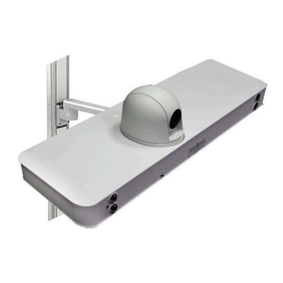
A standard Cisco Touch 10 controller can also be connected to the MedView, if required. This user guide covers the functionality and installation of the Iron Bow MedView Figure 1. -
Page 9: System Description
4. Integrated System Speakers 5. Call Status Indicator 6. Integrated Microphone 7. Removable cap to access camera inversion switch 8. Cable Tie Bar 9. Integrated Cisco Webex Room Kit Plus (In custom enclosure) Figure 2. MedView system components Copyright 2021 Iron Bow Technologies... -
Page 10: System Installation
System Installation The MedView system can be mounted above, or below, a display as well as wall or ceiling mounted. The diagram below shows the overall system dimensions plus the mounting hole pattern in the base of the system. The basic mounting arrangement utilizes standard 100mm x 100mm VESA compliant mounting holes, which are available in two locations near the middle of the MedView. -
Page 11: Wall Mounting
Wall Mounting The MedView flexible mounting arrangement allows a variety of commercially available ceiling and wall brackets to be used, as well as custom brackets available for Iron Bow, described below. In selecting a commercial bracket, it is strongly recommended a device that will support 20 pounds is used. -
Page 12: Ceiling Mounting
Ceiling Mounting Once the camera orientation has been electronically reversed, the system can now be ceiling mounted or above the room display in an alcove, or similar. Multiple ceiling or “flat” mounting brackets are commercially available that will mate with the VESA mounting holes in the base of the MedView. -
Page 13: Figure 7 Medview Mounting Bracket Kit
Base Mounting Bracket 200mm/300mm Adaptor Plate Figure 7. MedView Mounting Bracket Kit An optional Universal Mounting Hardware Pack is available, containing a comprehensive set of screws, washers and spacers for attaching to the majority of commercially available displays . Iron Bow Universal Mounting Hardware Pack, Part # MEDVIEW-HDWR-A01 Description M4 x 12mm philips pan head screws M4 x 30mm philips pan head screws... -
Page 14: Attaching Medview To Display Mounting Bracket
T he MedView can be directly mounted to a display using the optional Iron Bow VESA mounting bracket kit, Part # MEDVIEW-C-BRKT300-A01. The combination of MedView and display can then be used in a tabletop configuration, or wall mounted, as required. -
Page 15: Attaching To Display
To attach the MedView to the top plate of the mounting bracket carefully place the MedView on a flat surface facing downwards being careful not to apply any pressure to the camera assembly. The MedView is then attached to the top plate using the supplied three M4 bolts, plus one ¼-20 bolt. -
Page 16: Figure 13 Center Line Attachment Locations
The front to rear adjustments are available to suit the best physical location for the device in relationship to the rear access for cabling, as well as to meet the aesthetic requirements of the installation. Camera off set Centerline of display Centerline of display Figure 13. -
Page 17: Figure 14 Medview Mounting Bracket Height Adjustment
Attaching MedView Mounting Bracket to Display Once the MedView has been attached to the mounting bracket in the required location, it can be attached to the display. The bracket is designed to sandwich between the VESA mount on the display and the VESA wall bracket as shown in Figure 14. In the event that the display is being used on a table stand, or similar, the MedView bracket can simply be attached directly to the VESA mount on the rear of the display. -
Page 18: Figure 16 Medview Adaptor Plate
Attaching MedView to Larger Displays To mount the MedView to a display which uses a larger VESA mounting pattern than 100mm x 100mm, the 200mm/300mm adaptor plate is needed. The mounting kit includes both the standard 100mm VESA mounting bracket plus the adaptor bracket for larger mounting patterns. -
Page 19: Figure 18 Assembling The 200Mm/300Mm Mounting Bracket
Assembling the 200mm/300mm MedView Mounting Bracket To attach the adaptor bracket to the base bracket, line up the three slots in adaptor plate with one of the sets of three attachment holes in the mounting plate using the provided bolts. As shown in Figure 12. there are three different sets of mounting holes in the base mount where the adaptor plate can be attached. - Page 20 Once the best location for attaching the adaptor plate to the standard bracket has been determined to match the display height, the combined assembly is mounted either directly to the display if it is desktop mounted, or sandwiched between the wall mounting bracket and display, as shown in Figure 10, above.
-
Page 21: System Connections
Presentation source Input #3 (HDMI) USB2 Connection for peripheral devices (e.g. Tethered Controllers) Auxiliary Microphone input #2 (4 pole 3.5mm jack – Cisco Spec.) Auxiliary Microphone Input #3 (4 pole 3.5mm jack – Cisco spec.) Infotainment System Input (HDMI – see system configuration for spec) Master System Output (HDMI –... -
Page 22: System Configuration
System Configuration Codec Configuration The MedView incorporates a Cisco Room Kit codec plus and for instruction how to manage the codec system settings please refer to the Cisco Webex Codec plus Administrator Guide: https://www.cisco.com/c/en/us/support/collaboration-endpoints/spark-room-kit-series/products- maintenance-guides-list.html NOTE: If you are managing the Cisco Webex Room Kit Plus Codec integrated into the CLINiC... -
Page 23: Connecting External Audio Devices
ACC-AUDIO-C-OVERBED-A01, which is supplied with a 25-foot cable. Please note the microphone inputs are 4 pole, 3.5mm Jack configured to the standard Cisco specification, allowing suitable external Cisco microphones to be connected such as the Cisco Table Microphone 20, or equivalent. -
Page 24: Getting Started
Getting Started Connect any required peripherals to the appropriate port(s) of the MedView before connecting to AC power. Powering On the MedView: Connect the MedView to AC power. This will automatically power on the codec, camera and all electronics of the system which takes approximately 2 minutes. During the power up phase the camera will go through an initialization routine ... -
Page 25: Powering Off The Medview
Powering Off the MedView Powering off the MedView is typically unnecessary. Most video endpoints remain connected to the network and in stand-by mode until a call is placed or received. If you need to move the MedView to a different location, simply disconnect and re-connect the AC power, as needed. -
Page 26: Medview Administration
You can modify the default functions of the MedView codec by logging in as an administrator to the codec web interface and performing the desired changes. For the complete set of instructions, please refer to the Cisco Webex Codec plus Administrator Guide: https://www.cisco.com/c/en/us/support/collaboration-endpoints/spark-room-kit-... -
Page 27: Changing Standby Settings
Changing Standby Settings The default system configuration goes into standby mode after 1 minute with no activity. You can change this setting to disable standby mode or change the delay after which the system goes into standby. To change standby settings, navigate to Setup>System Configuration>Standby. To disable stand-by mode: Set Standby Control to Off. -
Page 28: Changing Conference Settings (Tethered Remote Only)
Change Conference Settings Optional Tethered Remote Only The default setting is set for the MedView to auto answer incoming calls. This can be changed to manual answering using the connect button on the system control panel To change conference call settings, navigate to Setup>Configuration>Conference. To Disable Auto Answering of Incoming Calls: Set AutoAnswer Mode to Off. -
Page 29: System Auto-Dial Operation (Tethered Remote Only)
System Auto-Dial Optional Tethered Remote Only A single contact can be auto-dialed from the MedView using the connect To add an auto-dial contact, navigate to Setup>Configuration>Facility/Service. Locate Service 5 and select Call Type: Video Input a identifying User name and associated URL Select Type: Other Select: Save Copyright 2021 Iron Bow Technologies... -
Page 30: Appendix.1. Physical And Electrical Specifications
Appendix.1. Physical & Electrical Specifications Dimensions • 31” Wide • 7.125” High (Includes camera) • 8.5” Deep (Chassis only – Excludes cable tie bar adds 1.25”) Weight 17 lbs. (Excluding external cabling and mounting brackets) Mounting Multiple base mounting points (see below) Compatible with 100mm x 100mm VESA mounts (refer to System Installation section of this manual) Electrical Integrated auto sensing power supply 100-240V~50/60Hz, 1.4A –... -
Page 31: Appendix.2. Tethered Remote Volume Control
Appendix.2. – Tethered Remote Volume Control The MedView is often used in an environment where it is wall mounted above a display and is set to auto answer an incoming call. In this configuration, there may be a requirement for the volume level of the system to be adjusted within the room. -
Page 32: Appendix.3. Tethered Remote Control
Appendix. 3. – Tethered Remote Control As an option for the MedView, a tethered remote control is available that can be used within the room for controlling basic system functions, as outlined below. The tethered remote control is fitted with a coiled cable which is a nominal 28” in length when fully closed and can expand to approximately 60”... -
Page 33: Control Panel Functions
Control Panel Functions The MedView Tethered Remote control panel buttons functions are described below: Description: 1. Pan and tilt the camera (2nd function: moves self-view PIP) 2. Zoom camera in. 3. Zoom camera out 4. Decrease speaker volume. 5. Increase speaker volume 6. -
Page 34: Managing Calls
Managing Calls This section describes how to manage calls by using the Tethered Remote Control. For instructions on how to manage calls using the optional Cisco Touch 10 Control Panel, please refer to the Cisco Webex Codec User Guide: https://www.cisco.com/c/dam/en/us/td/docs/telepresence/endpoint/ce98/touch10-sx10-sx20-sx80- mx200g2-mx300g2-mx700-mx800-room-kit-user-guide-ce98.pdf... -
Page 35: Managing Video Settings
Managing Video Settings This section describes how to manage video settings by using the Tethered Remote Control. For instructions on how to manage video settings please refer to the Cisco Webex Codec plus Administrator Guide: https://www.cisco.com/c/en/us/support/collaboration-endpoints/spark-room-kit- series/products-maintenance-guides-list.html Enabling and Disabling Video Privacy Mode Video Privacy selection stops the image from the system main camera being transmission. - Page 36 Enabling and Disabling Self-View Mode Self -View selection brings up a small window on the main screen showing the image being transmitted from the main system camera. A second selection removes the self-view window. Self-View Mode Image Location “PIP Location Mode” Pressing and holding the Self -View control for 5 seconds, then releasing, activates the PIP location mode which is indicated by an on screen message: Use the arrows to move the pip, press the ‘self view’...
-
Page 37: Managing Audio Settings
Managing Audio Settings This section describes how to manage audio settings by using the integrated control panel. For instructions on how to manage audio settings, please refer to the Cisco Webex Codec plus Administrator Guide: https://www.cisco.com/c/en/us/support/collaboration-endpoints/spark-room-kit- series/products-maintenance-guides-list.html Enabling and Disabling Microphone Mute Mode Microphone Mute selection stops the room audio from being transmitted to the remote site. -
Page 38: Appendix.4. Optional Ceiling Microphone
Appendix. 4. – Optional Ceiling Microphone A Ceiling Microphone assembly is available as an option for the MedView, which has been designed to increase the audio pick up of a specific location within the room. The complete assembly is normally ceiling mounted in a location that give an optimal pick up angle to maximize the audio captured by the internal microphone. -
Page 39: Appendix.5. Medview Base Mounting Bracket
Appendix. 5. – Cisco MedView Base Mounting Bracket Copyright 2021 Iron Bow Technologies... -
Page 40: Appendix.6. Medview 200Mm/300M Adaptor Plate
Appendix. 6. – Cisco MedView 200mm/300m Adaptor Plate Copyright 2021 Iron Bow Technologies... - Page 41 This Page Intentionally Left Blank Copyright 2021 Iron Bow Technologies...
- Page 42 This Page Intentionally Left Blank Copyright 2021 Iron Bow Technologies...
- Page 43 This Page Intentionally Left Blank Copyright 2021 Iron Bow Technologies...
- Page 44 2303 Dulles Station Boulevard, Suite 400 Herndon, VA 20171 Toll: 800.338.8866 Tel: 703.279.3000 Copyright 2021 Iron Bow Technologies...