Advertisement
- 1 Changing the faceplate
- 2 Single-pole Installation
- 3 Timer on LOAD side 3-way installation instructions
- 4 Timer on the LINE side 3-way installation instructions
- 5 Overview
- 6 Setting up the timer for the first time
- 7 Setting the dawn/dusk region (zone)
- 8 Programming Instructions
- 9 Additional programming options
- 10 Additional Features
- 11 Troubleshooting
- 12 Documents / Resources

RISK OF ELECTRIC SHOCK
- SHUT OFF POWER AT FUSE BOX OR CIRCUIT BREAKER BEFORE INSTALLATION
- DO NOT USE IN WET LOCATIONS
- USE INDOORS ONLY
RISK OF FIRE
- DO NOT USE TO CONTROL APPLIANCES THAT CONTAIN HEATING ELEMENTS (COOKING APPLIANCES, HEATERS, IRONS, ETC.)
- DO NOT EXCEED ELECTRICAL RATINGS
- DO NOT USE TO CONTROL RECEPTACLES
- USE COPPER WIRE ONLY WITH THIS DEVICE
- TIGHTEN ALL CONNECTIONS TO 1-1.4 N-m (8.85 TO 12.39 LBF-IN.)
- FOR SUPPLY CONNECTIONS, USE 14 AWG OR LARGER WIRE RATED AT LEAST 75°C.
- FOR GROUNDING LEAD, USE 12 AWG OR LARGER WIRE RATED AT LEAST 75°C.
Changing the faceplate
This device includes a light almond faceplate. To switch faceplates, proceed as follows:
- Gently remove the white faceplate using a flat head screwdriver. Find the slots at the bottom left or right of the white faceplate and pry the faceplate loose (see Figure 1). Work around the faceplate until it pops off.
![]()
- Find the light almond faceplate in the package. Place the new faceplate into position and carefully push the bottom of the faceplate until it snaps into place.

Single-pole Installation
NOTE: If you are unsure or unclear about this installation or if the wires in your box do not match the manual (not all switch boxes have neutral wires), contact a qualified, licensed electrician.
Installation instructions (single-pole)
- Turn OFF the main power at the circuit breaker or fuse box.
- Remove the existing switch.
- Connect the timer to the wall box wires as shown in Figure 2.

- Connect the hot/live LINE wire to the LINE terminal of the timer.
- Connect the hot/live LOAD wire to the LOAD terminal of the timer.
- Connect the Ground wire to the GROUND terminal of the timer.
- Connect the Neutral wire to the NEUTRAL terminal of the timer. Often the Neutral wire can be found in the back of the wire box connected with a wire nut. There may be several neutral wires bound together. Add the timer Neutral wire to the other neutral wires, bound together making sure the wire nut is tight. If needed use the included jumper.
- Ensure that all terminals are tightened to between 8.85 and 12.39 lbf-in., and tuck the wires into the wall box, leaving room for the timer.
- Use the screws to mount the timer to the wall box, being careful not to crush any wires.
- Reinstall your wallplate.
- Turn the main power on at the circuit breaker.
- If the timer does not turn on, disconnect the power at the circuit breaker or fuse box. Swap the LINE and LOAD wires on the timer. Remount the timer and wallplate, then restore power at the fuse box or circuit breaker.

Timer on LOAD side 3-way installation instructions
NOTE: If you are unsure or unclear about this installation or if the wires in your box do not match the manual (not all switch boxes have neutral wires), contact a qualified, licensed electrician.
Preparing the switch on the LINE Side
- Disconnect the power from the circuit by turning off the circuit breaker or removing the fuse from the fuse box.
- Using the LINE Side of Figure 3 as a visual reference, label and remove the LINE wire (1) from the common terminal (C) and the Traveler-2 wire (7) from the HOT terminal (H).

In a typical 3-way application there are two 3-way switches. The switch on the "HOT" side has the common terminal tied to 120VAC. The switch on the "LOAD" side has the common terminal tied to the load that the switches turn on and off. - Using Figure 4 as a visual reference, connect the jumper wire (6) (supplied), the LINE wire (1) from the common terminal (C), and the Traveler-2 wire (7) together. You should have three wires connected with one wire nut.

- Connect the other end of the jumper wire (6) back to the common terminal (C) on the switch. Consider recording the marking/color coding of the Traveler-1 (5) and Traveler-2 (7) wires so you can tell them apart for later use.
- Carefully tuck the wires into the box, leaving room for the switch.
- Install the switch back into the box.


Installing the timer on the LOAD Side
- Using the Load Side of Figure 3 as a visual reference, remove the LOAD Side 3-way switch and the four wires, labeling the wire removed from the common terminal as LOAD (4) and the wires from the HOT terminals (H) as Traveler-1 (5) and Traveler-2 (7).
- Using the Timer On LOAD Side of Figure 4 as a visual reference for the remaining steps, connect the LOAD wire (4) to the LOAD terminal of the timer.
- Connect the Traveler-2 wire (7) to LINE terminal of the timer.
- Connect the Traveler-1 wire (5) to the TRAVELER terminal of the timer.
- Connect the white Neutral wire (2) from the switch box to the NEUTRAL terminal of the timer. More neutral wires may be bundled in the back of the switch box; there may be several neutral wires bound together with a wire nut. Add the Neutral wire to the other neutral wires bound together, ensuring the wire nut is tight. If needed use included jumper.
- Connect the green Ground wire (3) in the switch box to the GROUND terminal of the timer.
- Carefully tuck the wires into the switch box, leaving room for the timer.
- Use the supplied screws to install the timer, being careful not to crush or pinch the wires.
- Restore power at the circuit breaker or fuse box.
- Verify that the LOAD turns ON/OFF when you manually turn the timer ON and OFF. Perform this test with the remote switch in both positions. You should hear the timer relay click ON/OFF. If you hear the relay click but the LOAD does not turn ON/OFF properly, check your wiring.
- If the load does not operate properly, disconnect the power at the circuit breaker or fuse box. Then swap the Traveler-2 (Line) wire (7) and Traveler-1 wire (5) on the timer.
Timer on the LINE side 3-way installation instructions
NOTE: If you are unsure or unclear about this installation or if the wires in your box do not match the manual (not all switch boxes have neutral wires), contact a qualified, licensed electrician.
Preparing the switch on the LOAD side
- Disconnect the power from the circuit by turning off the circuit breaker or removing the fuse from the fuse box.
- Using the Switch On LOAD Side of Figure 5 as a visual reference, label and remove the LOAD wire (4) from the common terminal (C) and the Traveler-2 wire (7) from the HOT terminal (H).

In a typical 3-way application there are two 3-way switches. The switch on the "HOT" side has the common terminal tied to 120VAC. The switch on the "LOAD" side has the common terminal tied to the load that the switches turn off and on. - Using Figure 6 as a visual reference, connect the jumper wire (6) (supplied), the LOAD wire (4) from the common terminal (C), and the Traveler-2 wire (7) together. You should have three wires connected with one wire nut. If needed use the included jumper.

- Connect the other end of the jumper wire (6) back to the common terminal (C) on the switch. Consider recording the marking/color coding of the Traveler-1 (5) and Traveler-2 (7) wires so you can tell them apart for later use.
- Carefully tuck the wires into the switch box leaving room for the timer.
- Install the switch back into the box.


Installing the timer on the LINE side
- Using the LINE Side of Figure 5 as a visual reference, remove the LINE Side 3-way switch and the four wires, labeling the wire removed from the common terminal (C) as LINE (1) and the wires from the HOT terminals (H) as Traveler-1 (5) and Traveler-2 (7).
- Using the Timer on LINE Side of Figure 6 as a visual reference for the remaining steps, connect the LINE wire (1) to the LINE terminal of the timer.
- Connect the white Neutral wire (2) to the NEUTRAL terminal of the timer. More neutral wires may be bundled together in the back of the switch box; there may be several neutral wires bound together with a wire nut. Add the Neutral wire to the other neutral wires bound together, ensuring the wire nut is tight.
- Connect the Traveler-1 wire (5) to the TRAVELER terminal of the timer and the Traveler-2 wire (7) to the LOAD terminal of the timer.
- Connect the green Ground wire (3) to the GROUND terminal of the timer.
- Carefully tuck the wires into the switch box, leaving room for the timer.
- Use the supplied screws to install the timer, being careful not to crush or pinch the wires.
- Restore power at the circuit breaker or fuse box.
- Verify that the LOAD turns ON/OFF when you manually turn the timer ON and OFF. Perform this test with the remote switch in both positions. You should hear the timer relay click ON/OFF. If you hear the relay click but the LOAD does not turn ON/OFF properly, check your wiring.
- If the load does not operate properly, disconnect the power at the circuit breaker or fuse box. Then swap the Traveler-2 (LOAD) wire (7) and Traveler-1 wire (5) at the timer or the toggle switch.
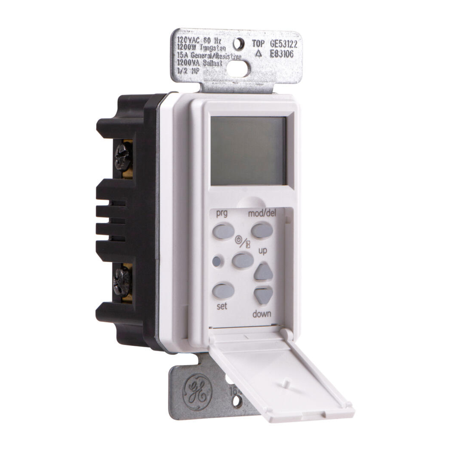
Overview

- PROGRAM (prg): Press to set daily ON/OFF times.
- MODE/DELETE (mod/del): Press to choose from auto, manual or random modes. When the timer is in Program mode (prg), this button deletes program settings.
- RESET: Push to reset the timer to default settings.
- ON/OFF and TIMER OVERRIDE: Press to turn load ON/OFF and press and hold to start the Countdown function.
- SET: Press to set the calendar, clock, dusk, dawn and daylight savings settings.
- UP/DOWN BUTTONS: Press to scroll through timer setting options.
- TIMER DOOR: Close after programming. Press to turn ON/OFF (TIMER OVERRIDE).
NOTE: The timer will automatically return to the clock mode if a button is not pushed for 60 seconds. Push the setup button once to return to program mode if this happens.
Setting up the timer for the first time
- Using a toothpick or a pencil, gently press RESET (C) to clear all programming and set the timer to default settings.
- Press the SET (E) button to begin setting the time and calender. The time "12:00 AM" will be flashing. See Figure 7.
![]()
- Use the UP/DOWN (F) buttons to set the current time, taking note of the AM and PM on the display. Press SET (E) when the current time is displayed.
- Use the UP/DOWN (F) buttons to select the year then press SET (E).
- Use the UP/DOWN (F) buttons to set the month then press SET (E).
- Use the UP/DOWN (F) buttons to set the day then press SET (E).
- When DST appears on the display (see Figure 8), use the UP/ DOWN (F) buttons to turn DST ON/OFF then press SET (E).
![]()
NOTE: Choose DST ON if your local area observes Daylight Savings Time. The timer will automatically adjust backwards and forwards an hour. Choose DST OFF if your local area does not observe Daylight Savings Time. - If you selected DST ON, the display flashes "ZONE." Proceed to SETTING THE DAWN/DUSK REGION (ZONE) below.


NOTE: This step does not set your time zone. In this step you are identifying your location based on this map to ensure an accurate dawn and dusk time for your area.
Setting the dawn/dusk region (zone)
View Figure 9 and determine which zone best fits your location using the up arrow. The options are NOR: North, CENT: Central, SOUT: South, ALAS: Alaska, and HAWA: Hawaii

- Use the UP/DOWN (F) buttons to select the zone where the timer is installed then press SET (E). See Figure 10.
![]()
- Use the UP/DOWN (F) buttons to set the dusk time then press SET (E). The approximate dusk time will be flashing. The approximate time may be changed + or – 2 hours in order to find the desired dusk time. See Figure 11A.
![]()
- Use the UP/DOWN (F) buttons to set the dawn time then press SET (E). The approximate dawn time will be flashing. The approximate time may be changed + or – 2 hours in order to find the desired dawn time. See Figure 11B.
![]()
- Press SET (E) to complete setup and the timer will return to clock mode.


Programming Instructions
Programming the ON/OFF days
- Press the PROGRAM (prg) (A) button to begin programming times. The display will show Program 1 on. See Figure 12. Press PROGRAM (prg) (A) to scroll through the remaining ON/OFF programs until you reach an available program (if you are programming multiple programs). There are 7 ON/OFF programs available. Once you are on the correct program press SET (E).
![]()
- Use the UP arrow (F) button to scroll the days of the week the timer will activate:
MO, TU, WE, TH, FR, SA, SU (Default)
MO through SU: Individual days
MO, TU, WE, TH, FR
SA, SU
SU, MO, TU, WE, TH
FR, SA - Press SET (E) to select your desired days of the week setting. Proceed to Step 2 - Programming the ON/OFF time.

Programming the ON/OFF time
- Press UP/DOWN buttons (F) to choose from one of these three options tobegin configuring the timer's ON time. Press SET (E) to choose your setting option and PROGRAM (prg) (A) to proceed to Step 2.
TIME: Press the UP/DOWN (F) buttons to set any customer time, taking note of the AM/PM on the display. See Figure 13.
![]()
DUSK: Sets the timer to the DUSK time that is displayed. See Figure 14.
![]()
DAWN: Sets the timer to the DAWN time that is displayed. See Figure 15.
![]()
- Press UP/DOWN buttons (F) to choose from one of the three options to begin configuring the timer's OFF time. Press SET (E) to choose your setting option and PROGRAM (prg) (A) to proceed to Step 3.
- Repeat Steps A and B to set additional programmed ON/OFF times (up to 7 total).
To exit programming mode and return to clock mode, press and hold the PROGRAM (prg) (A) button for 3 seconds, or do not press any buttons for 20 seconds.


Additional programming options
Reviewing programs
Press the PROGRAM (prg) (A) button to scroll through the existing ON/OFF programs (7 maximum).
Deleting programs
Press the PROGRAM (prg) (A) button to scroll through the existing ON/OFF programs. Stop on the program to be delete and press MODE/DELETE (mod/del) (B) to delete. The screen will show the program has been deleted.
Setting the random (RND) security option
The Random (rnd) feature will turn lights on and off using the programmed times + or - 30 minutes, giving the house a more lived in appearance while the occupant is away.
To activate Random, press MODE/DELETE (mod/del) (B) until RND flashes on the screen. To turn off, press MODE/DELETE (mod/del) (B) again to enter the manual or automatic setting. See Figure 16.

Additional Features
Using the three available timer modes (optional)
Press MODE/DELETE (mod/del) (B) to scroll through the available modes.
AUTO - (Automatic) Timer is set to Automatic and will follow the selected program (1-7).
MANU - (Manual) Timer does not follow a program. Turn the lights ON and OFF by pressing the door (G).
RND - (Random) Timer will turn lights on and off using one of the existing program times + or - 30 minutes.
Countdown mode
Press and hold the ON/OFF (D) button for about 3 seconds.
- Use UP/DOWN (F) buttons to select countdown time (default is 1 hour). See Figure 17.
![]()
- Stop on the time desired and the timer will countdown. The time chosen will become the new default. If using default countdown time of 1 hour, press the door (G) for 3 seconds and countdown function will begin. Lights will turn off once countdown has completed. Hold the ON/OFF (D) button for 3 seconds to cancel the countdown.

Troubleshooting
3-way switch will not work.
- Make sure jumper wiring is correct.
Lights on all day controlled by timer.
- Check to make sure the clock time is set for correct AM/PM.
- Check to make sure Dusk time and Dawn time are not reversed.
Lights come on and off at times different than they programmed.
- Check to see if there are multiple programs on the timer that conflict with each other.
- 3-way switch may have been used to turn lights off or on; the timer should function correctly during the next program cycle.
MADE IN CHINA
GE is a trademark of General Electric Company and is under license by Jasco Products Company LLC, 10 E. Memorial Rd., Oklahoma City, OK 73114.
This Jasco product comes with a 1-year limited warranty. Visit www.byjasco.com for warranty details.
Questions? Contact us at 1-800-654-8483 between 7:00AM—8:00PM CST.

Step-by-Step Instructional Video

Documents / Resources
References
Download manual
Here you can download full pdf version of manual, it may contain additional safety instructions, warranty information, FCC rules, etc.
Advertisement
Thank you! Your question has been received!


Need Assistance?
Do you have a question about the SunSmart Digital Timer that isn't answered in the manual? Leave your question here.