Bosch B308 - Octo-Output Module Installation Manual
- Installation manual (2 pages)
Advertisement
Overview
This module is a supervised device that provides 8 programmable outputs (Form C relays) and connects to control panels through the SDI2 bus.

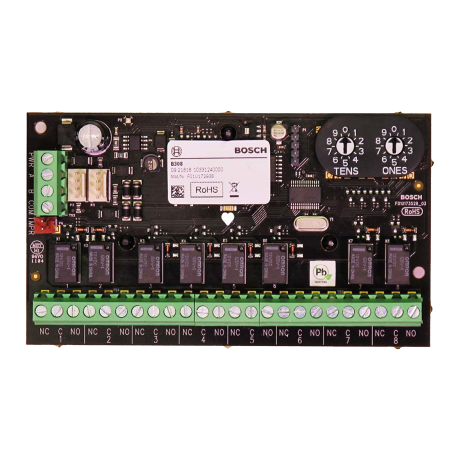
Callout ― Description
- SDI2 interconnect connectors - connect SDI2 control panel and SDI2 devices
- SDI2 terminal strip - connect SDI2 control panel and SDI2 devices
- Tamper switch connector
- Terminal strip (outputs)
- Heartbeat LED (blue)
- Address switches
SDI2 address settings
 NOTICE!
The module reads the switch setting only during power up. Cycle the power to the module to enable the new setting.
Set the switches per the control panel configuration. Each B308 module must have a unique address.
The module's switches provide a tens and ones value for the module's address. For single-digit address numbers 1 through 9, set the tens switch to 0 and the ones digit to the appropriate number. The following illustration shows the address switches setting for addresses 1 and 11.

Valid addresses and output numbers per control panel
Valid B308 addresses are dependent on the number of outputs allowed by a particular control panel.
| Control panel | Valid B308 addresses | Corresponding output numbers |
| B9512G | 01 - 59 | 11 - 18, 21 - 28, 31 - 38, 41 - 48, 51 - 58, 61 - 68, 71 - 78, 81 - 88, 91 - 98, 101 - 108, 111 - 118, 121 - 128, 131 - 138, 141 - 148, 151 - 158, 161 - 168, 171 - 178, 181 - 188, 191 - 198, 201 - 208, 211 - 218, 221 - 228, 231 - 238, 241 - 248, 251 - 258, 261 - 268, 271 - 278, 281 - 288, 291 - 298, 301- 308, 311 - 318, 321 - 328, 331 - 338, 341 - 348, 351 - 358, 361 - 368, 371 - 378, 381 - 388, 391 - 398, 401 - 408, 411 - 418, 421 - 428, 431 - 438, 441 - 448, 451 - 458, 461 - 468, 471 - 478, 481 - 488, 491 - 498, 501 - 508, 511 - 518, 521 - 528, 531 - 538, 541 - 548, 551 - 558, 561 - 568, 571 - 578, 581 - 588, 591 - 598 |
| B8512G | 01 - 09 | 11 - 18, 21 - 28, 31 - 38, 41 - 48, 51 - 58, 61 - 68, 71 - 78, 81 - 88, 91 - 98 |
| B6512 | 01 - 09 | 11 - 18, 21 - 28, 31 - 38, 41 - 48, 51 - 58, 61 - 68, 71 - 78, 81 - 88, 91 - 96 |
| B5512 | 01 - 05 | 11 - 18, 21 - 28, 31 - 38, 41 - 48, 51 - 58 |
| B4512 | 01 - 03 | 11 - 18, 21 - 28, 31 - 38 |
| D9412GV4 | 01 - 12 | 11 - 18, 21 - 28, 31 - 38, 41 - 48, 51 - 58, 61 - 68, 71 - 78, 81 - 88, 91 - 98, 101 - 108, 111 - 118, 121 - 128 |
| D7412GV4 | 01 - 06 | 11 - 18, 21 - 28, 31 - 38, 41 - 48, 51 - 58, 61 - 64 |
| D7212GV4 | 01 - 02 | 11 - 18, 21 - 24 |
To find the output numbers for each address, multiply the address number by 10 for the base number, and then use numbers 1 through 8 in the ones place for the output numbers.
For examples, refer to Section "Point number examples".
Installation

Remove all power (AC and battery) before making any connections. Failure to do so might result in personal injury and/or equipment damage.
Install the module in the enclosure
Refer to the following illustration for installing into the enclosure.

Callout ― Description
- Module with mounting bracket installed
- Enclosure
- Mounting screws (3)
Install and wire the tamper switch
You can connect an optional enclosure door tamper switch for one module in an enclosure.
- Put the ICP-EZTS Tamper Switch (P/N: F01U009269) into the enclosure's tamper switch mounting location. For complete instructions, refer to EZTS Cover and Wall Tamper Switch Installation Guide (P/N: F01U003734).
- Plug the tamper switch wire onto the module's tamper switch connector.
Attach to the control panel
Use either the module's terminal strip labeled with PWR, A, B, and COM, or the module's interconnect wiring connectors (wire included) to attach to the control panel. Interconnect wiring parallels the PWR, A, B, and COM terminals on the terminal strip. Refer to the following illustrations for wiring.
NOTICE!
Use the terminal strip wiring or interconnect wiring connector to the control panel. Do not use both. When connecting multiple modules, combine terminal strip and interconnect wiring connectors in series.

Callout ― Description
- Terminal strip wiring (SDI2)
- Interconnect cable (P/N: F01U079745) (included)

Callout ― Description
- Bosch control panel
- B308 modules

Callout ― Description
- Bosch control panel
- B308 modules
Relay output wiring
Each output provides a NO and a NC output. The NO, C (COMMON), and NC terminals are available in each terminal or connection output position. The silkscreen on the edge of the circuit board shows the function of each terminal and the relay output number.
The middle terminal of each output position is the COMMON and is labeled C. When the output is inactive, the NC (Normally Closed) terminal has continuity with the C terminal. When the output is active (energized), the NO (Normally Opened) has continuity with the C terminal.
NOTICE!
Do not exceed relay contact ratings of 1.0 A, 24 VDC, resistive load.
LED descriptions
The module includes one heartbeat LED to indicate that the module has power and to indicate the module's current state. Refer to the following table.
| Flash Pattern | Function |
Flashes once every 1 second | Normal operation state. |
3 quick flashes every 1 second | Communication error state: Indicates an SDI2 communication error. |
ON Steady | LED trouble state: Not powered (for OFF Steady only), or some other trouble condition. |
OFF Steady |
Show the firmware version
With a tamper switch:
- Open the enclosure door.
- Push and release the switch
Without a tamper switch:
- Quickly short the tamper pins.
- Refer to the illustration below.

When the tamper switch is on, the heartbeat LED stays OFF for 3 second before showing the firmware version. The LED flashes the major, minor, and micro digits of the firmware version, with a 1 second pause after each digit.
For example, the version 1.4.3 shows as LED flashes: [3 second pause] *___****___*** [3 second pause, then normal operation].
Certifications
| Region | |
| US | UL 365 - Police Station Connected Burglar Alarm Units and Systems |
| UL 609 - Local Burglar Alarm Units and Systems | |
| UL 864 - Control Units and Accessories for Fire Alarm Systems | |
| UL 985 - Household Fire Warning System Units | |
| UL 1023 - Household Burglar-Alarm System Units | |
| UL 1076 - Proprietary Burglar Alarm Units and Systems | |
| UL 1610 - Central-Station Burglar-Alarm Units | |
| CSFM - California Office of The State Fire Marshal | |
| FCC Part 15 Class B | |
| FDNY - Fire Department of New York | |
| FM Approval 3010 | |
| Canada | CAN/ULC-S303 Local Burglar Alarm Units and Systems |
| CAN/ULC-S304 Central and Monitoring Station Burglar Alarm Units | |
| ICES-003 - Information Technology Equipment (ITE) | |
| ULC/ORD-C1023 Household Burglar Alarm System Units | |
| ULC/ORD-C1076 Proprietary Burglar Alarm Units and Systems |
Specifications
| Dimensions | 2.9 in x 5.0 in x 0.6 in (73.5 mm x 127 mm x 15.25 mm) |
| Voltage (operating) | 12 V nominal |
| Current (maximum) | 150 mA (22 mA for digital section + 16 mA per energized relay) |
| Operating temperature | +32°F to +122°F (0°C to +50°C) |
| Relative humidity | 5% to 93% at +90°C (+32°C) noncondensing |
| Relay outputs | Dry contacts rated for.001 to 1.0 A at 5 to 24 VDC (resistive load). |
| Terminal wire size | 12 AWG to 22 AWG (2 mm to 0.65 mm) |
| SDI2 wiring | Maximum distance - Wire size (Unshielded wire only): 400 ft (122 m) - 22 AWG (0.65 mm) 1000 ft (305 m) - 18 AWG (1.02 mm) |
| Compatibility | B9512G/B9512G-E B8512G/B8512G-E B6512 B5512/B5512E B4512/B4512E D9412GV4/D7412GV4/D7212GV4 (Refer to the control panel installation document for number of supported devices.) |
Point number examples
For B308 address 01 the output numbers for the output devices are 11 through 18:
| Terminal no | 1 | 2 | 3 | 4 | 5 | 6 | 7 | 8 |
| Output no | 11 | 12 | 13 | 14 | 15 | 16 | 17 | 18 |
For B308 address 11 the output numbers for the output devices are 111 through 118:
| Terminal no | 1 | 2 | 3 | 4 | 5 | 6 | 7 | 8 |
| Output no | 111 | 112 | 113 | 114 | 115 | 116 | 117 | 118 |
Copyright
This document is the intellectual property of Bosch Security Systems, Inc. and is protected by copyright. All rights reserved.
Trademarks
All hardware and software product names used in this document are likely to be registered trademarks and must be treated accordingly.
Bosch Security Systems, Inc. product manufacturing dates Use the serial number located on the product label and refer to the Bosch Security Systems, Inc. website at http://www.boschsecurity.com/datecodes/.
Bosch Security Systems, Inc.
130 Perinton Parkway
Fairport, NY 14450
USA
Bosch Sicherheitssysteme GmbH
Robert-Bosch-Ring 5
85630 Grasbrunn
Germany

Documents / Resources
References
![www.boschsecurity.com]() Datecodes | Bosch Security and Safety Systems I Global
Datecodes | Bosch Security and Safety Systems I Global![www.boschsecurity.com]() Home | Bosch Security and Safety Systems I Global
Home | Bosch Security and Safety Systems I Global
Download manual
Here you can download full pdf version of manual, it may contain additional safety instructions, warranty information, FCC rules, etc.
Download Bosch B308 - Octo-Output Module Installation Manual
Advertisement
Thank you! Your question has been received!


Need Assistance?
Do you have a question about the B308 that isn't answered in the manual? Leave your question here.