Bosch B920 - Two-Line Alphanumeric Keypad Installation Manual
- Quick start manual (3 pages) ,
- Installation manual (2 pages) ,
- User quick reference manual (2 pages)
Advertisement
Overview
This keypad is SDI2 compatible. Multiple keypads can be connected to the control panel by wiring them in parallel.

| Callout ― Description |
| 1 ― Wall mount holes |
| 2 ― Single gang box holes |
| 3 ― Double gang box holes |
| 4 ― Wire opening |
| 5 ― Surface mount wire openings |
| 6 ― Gang box holes (3-4 in) |
| 7 ― Surface mount wire channel |
| 8 ― Bubble level |
| 9 ― SDI2 wiring terminal block |
| 10 ― Wire tie posts |
SDI2 address switches
Two switches determine the address for the keypad. The control panel uses the address for communications. To set the switches, use a slotted screwdriver.
Access the address switches
- Use a slotted screwdriver. Turn the lock counterclockwise.
- Push down on the keypad to remove it from the base.
- Find the switches on the back of the keypad.
Refer to the following illustrations.


| Callout ― Description |
| 1 ― Address switches |
Setting the address switches
Set the address switches per the control panel configuration.
If multiple SDI2 keypads reside on the same system, each SDI2 keypad must have a unique address. For single-digit addresses 1 through 9, set the tens switch to 0. The following illustration shows the address switch setting for address 1.

Installing

Remove all power (AC and battery) before making any connections. Failure to do so might result in personal injury and/or equipment damage.
Installing the keypad
You can surface install the keypad, or install it to standard electrical boxes, including single gang boxes.
- Use the base as a template to mark surface.
- Pull the wiring through the opening in the base.
- Use the mounting hardware to attach.
Attaching to the control panel
Use the control panel terminals labeled R, Y, G, B (PWR, A, B, COM). Connect them to the keypad terminals labeled R, Y, G, B. Keypads can be wired directly to the control panel or from keypad to keypad.

| Callout ― Description |
| 1 ― Control panel |
| 2 ― Terminal wiring |
| 3 ― Keypad's wiring terminal block |

Reconnect the keypad to the base by sliding the keypad onto the base (reverse of Step 2). Apply power to the system.
Display
Adjusting brightness:
- Push [MENU] to open.
- Push [NEXT] to go to the Press 5 for Settings Menu option, or press [5].
- Push [NEXT] to go to the Press 4 for Keypad Config option, or press [4].
- Push [1] to adjust the brightness.
- Push [PREV] or [NEXT] to adjust the brightness. The changes apply immediately.
- Push [ESC] to exit.
Adjusting nightlight (for control panels with version 2.01 or higher):
- Push [MENU] to open.
- Push [NEXT] to go to the Press 5 for Settings Menu option, or press [5].
- Push [NEXT] to go to the Press 4 for Keypad Config option, or press [4].
- Push [NEXT] to go to the Press 4 for Nightlight option, or press [4].
- Push [PREV] or [NEXT] to toggle between Yes and No.
- Push [ENTER] while viewing the option to save the programming.
- Push [ESC] to exit.
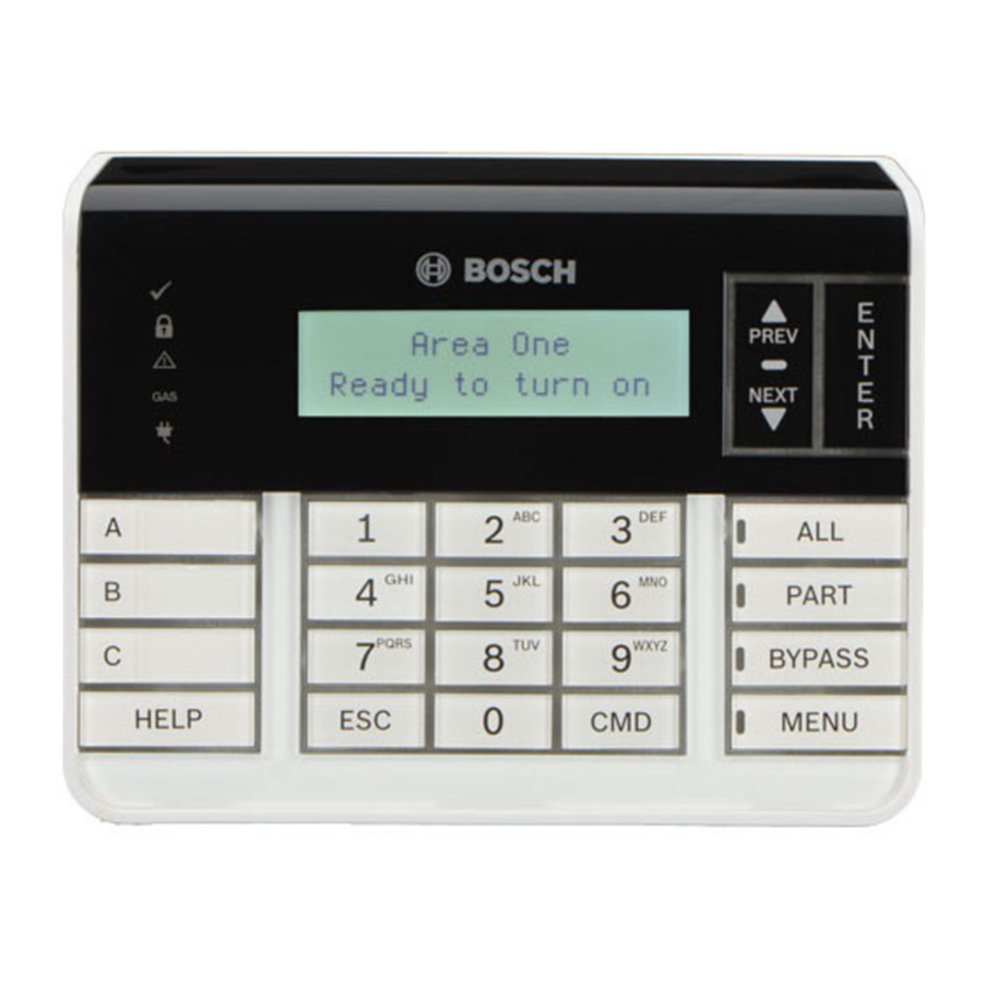
Status indicators
| Status indicator | Function |
 | Ready to turn on (arm) |
 | Turned on (armed) |
 | System trouble |
| GAS | Gas alarm |
 | AC power present |
Audible tones
The keypad has a built-in speaker that produces several distinct warning tones.
| Tone | Description |
| Fire alarm | Emits a pulsed, high-pitched bell tone. |
| Gas alarm | Emits a unique high pitched tone. |
| User alarm | The tone sounds for the programmed amount of time. |
| Burglary alarm | Emits a steady, high pitched bell tone. |
| Entry delay | Emits an intermittent beep tone during entry delay periods. |
| Exit delay | Emits an intermittent beep tone during exit delay. |
| Invalid button buzz | Emits a flat buzz tone. |
| Keypress | Emits a muted beep tone. |
| Trouble | Emits a two-tone warble until you enter a programmed passcode. |
| Watch point fault | Emits a single clean tweedle tone. |
Supervision
The control panel supervises all SDI2 devices. Any device that fails to respond will be declared missing.
Showing the firmware version
- To remove power to the keypad, remove it from the base.
- Return the keypad to the base to restore power. The keypad shows the model number, keypad address, and firmware version for 10 seconds.

NOTICE!
You can also view a keypad's firmware version in RPS.
Use a soft cloth or a non-abrasive cleaning solution. Spray the cleaner onto the cloth, not the keypad.
Specifications
| Dimensions | 6.2 in x 4.7 in x 1 in (158 mm x 120 mm x 26 mm) |
| Voltage (input) | 12 VDC nominal |
| Current | 35 mA in standby mode 70 mA in alarm mode |
| Operating temperature | 0°C to +50°C (+32°F to +122°F) |
| Relative humidity | 5% to 93% at +32°C (+90°F) non-condensing |
| Terminal wire size | 12 AWG to 22 AWG (2 mm to 65 mm) |
| SDI2 wiring | Maximum distance - wire size (unshielded wire only): 1000 ft (305 m) - 22 AWG (0.65 mm) |
| Compatibility | B9512G/B9512G-E B8512G/B8512G-E B6512/B5512/B4512/B3512 D9412GV4 version 2.0 and higher D7412GV4 version 2.0 and higher (Refer to the control panel installation document for number of supported devices.) |
Bosch Security Systems, Inc.
130 Perinton Parkway
Fairport, NY 14450
USA
www.boschsecurity.com
Bosch Sicherheitssysteme GmbH
Robert-Bosch-Ring 5
85630 Grasbrunn
Germany

Documents / Resources
References
Download manual
Here you can download full pdf version of manual, it may contain additional safety instructions, warranty information, FCC rules, etc.
Download Bosch B920 - Two-Line Alphanumeric Keypad Installation Manual
Advertisement
Thank you! Your question has been received!


Need Assistance?
Do you have a question about the B920 that isn't answered in the manual? Leave your question here.