
Related Manuals for Philips PAB90 1 Series

Summary of Contents for Philips PAB90 1 Series
- Page 1 PAB90x-1 Programming and Evaluation Board for LPC901, LPC902, LPC903 Getting Started Guide 2003 July 28 PAB90x-1 Getting Started V1.0 Page 1...
-
Page 2: Table Of Contents
Revision History Version Date Notes 07/28/03 First release Table of Contents 1. Overview 2. PAB90x-1 Programming Board Setup 3. Programming the P89LPC90x using PAB90x-1 4. Running User code on the LPC90x using PAB90x-1 5. Evaluating the P89LPC90x using PAB90x-1 6. Code Generation for LPC900 using Code Architect PAB90x-1 Getting Started V1.0 Page 2... -
Page 3: Overview
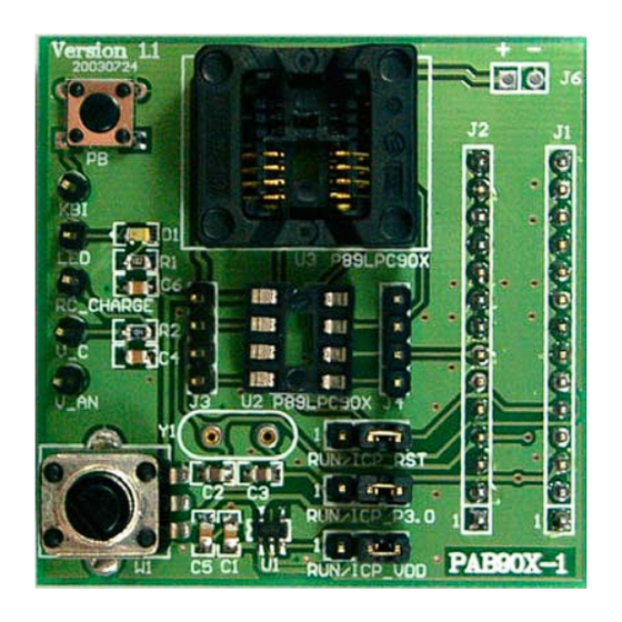
1. Overview PAB90x-1 (V1.1 and up) is a Programming and Evaluation Adapter Board for the Philips 8-bit microcontrollers LPC901, LPC902, LPC903 in an 8-pin package. (Whenever “LPC90x” is mentioned in this document, it refers to LPC901/902/903. To program other LPC90x devices, e.g. LPC906/907/908, you need a different programming adapter board called PAB90x-2.) - Page 4 • Push Button: A push button (PB) is provided as an external trigger in an application or to wake up the LPC90x from Power-Down mode. • Crystal Oscillator socket Different Crystal oscillator values can be tested in socket Y1. A 12 MHz crystal is provided. •...
-
Page 5: Pab90X-1 Programming Board Setup
Programming (IAP). Details on the ICP specification can be found on the included CD (folder “ICP Programming Specification”) FlashMagic is the preferred software used to perform ISP on the Philips Flash Microcontrollers that support this programming method. To provide the same... - Page 6 As already mentioned in the overview, the PAB90x-1 programming board is designed as an add-on board to the MCB900 board from Keil Software. Before any P89LPC90x devices can be programmed, the LPC932 microcontroller on the Keil MCB900 board needs to be programmed with the ISP-ICP bridge code using the ISP software FlashMagic (included on the CD).
- Page 7 • Connect the MCB900 to your PC COM port using a serial cable. • Power up the MCB900 board. • Start FlashMagic (Start | Programs | FlashMagic | FlashMagic) • Go to “Options | Advanced Options | Hardware Config” and make sure the box “Use DTR and RTS to enter ISP mode”...
- Page 8 • Click start program the ISP-ICP bridge code into the P89LPC932: PAB90x-1 Getting Started V1.0 Page 8...
- Page 9 Step 3) Attach the PAB90x-1 board to the MCB900 board • Disconnect the power cable from the MCB900 board • Set the jumper on the MCB900 board from “Reset” to “RUN” • Plug the PAB90x-1 programming board onto the MCB900. Make sure all 28 pins align correctly.
-
Page 10: Programming The P89Lpc90X Using Pab90X-1
3. Programming the LPC90x using PAB90x-1 Once all setups from the previous chapter have been made, using FlashMagic the LPC90x devices can be programmed in 5 steps corresponding to the numbered steps on the FlashMagic User Interface. Step 0. • Disconnect the power cable from the MCB900 board •... - Page 11 • At this point you can do a quick read of the device signature bytes to make sure you’re connected to the LPC90x: If FlashMagic cannot read the Device Signature or you get all FF’s, please check your setup. The correct signature bytes are: LPC901: 15h DDh 0Dh;...
-
Page 12: Running User Code On The Lpc90X Using Pab90X-1
4. Running User code on the LPC90x using PAB90x-1 When a device has been successfully programmed, use the following steps to run the programmed code: Step1: Disconnect the power cable from the MCB900 board Step 2: Put the 3 jumpers on the PAB90x-1 board to RUN mode Step 3: Reconnect power –... - Page 13 PAB90x-1 Getting Started V1.0 Page 13...
- Page 14 PAB90x-1 Getting Started V1.0 Page 14...
- Page 15 Other functions can be found in the ISP menu: PAB90x-1 Getting Started V1.0 Page 15...
-
Page 16: Evaluating The P89Lpc90X Using Pab90X-1
RC_CHARGE can be used to do a slope conversion Analog-to-Digital Converter (together with resistor R2 and capacitor C4). This slope conversion ADC is described in detail in Application Note AN10187, “Low-cost A/D-Conversion with Philips LPC Microcontrollers”. This Application Note (among others) is included on the CD. • Push Button:... - Page 17 • Crystal Oscillator socket Different Crystal oscillator values can be tested for the LPC901 in socket Y1. To use an external crystal, FlashMagic offers you to reprogram UCFG1, the User-Configuration Register of the LPC90x devices (ISP | Device Configuration): Please note: Only LPC901 features external crystal pin inputs. LPC902 and LPC903 can only be run from the internal RC oscillator or the internal Watchdog oscillator.
- Page 18 PAB90x-1 Getting Started V1.0 Page 18...
- Page 19 Using the LED, the Potentiometer and the Push-Button in a pre-programmed example There is an example program preprogrammed into the device sample that came with your PAB90x-1 board. The source code is included on the CD, in folder “LPC901_2_3 LED blinker and SD ADC”. The software blinks the LED with a frequency that depends on the position of the potentiometer.
- Page 20 Together with resistor R2 and capacitor C4, the software uses the on-chip analog comparator as a Sigma-Delta Analog to Digital Converter. This method is described in detail in AN10187, “Low-cost A/D-Conversion with Philips LPC Microcontrollers”. This Application Note (among others) is included on the CD.
- Page 21 6. Code Generation for LPC900 using For faster time to market, the Embedded Systems Academy (www.esacademy.com) developed a Code Generation tool for Philips LPC900 called Code Architect. Code Architect is a Web and PC based software tool that allows source code to be quickly and easily generated for Philips Microcontrollers.
- Page 22 version. This allows access to your Code Architect projects regardless of whether you are using a public PC, friend's PC, on a business trip, at the office or whether you have an Internet connection or not. The user interface is nearly identical in both Internet and Windows versions providing familiarity and ease of use.
- Page 23 Step 2 is to enter the options for the peripheral. PAB90x-1 Getting Started V1.0 Page 23...
- Page 24 The options have been made as user-friendly as possible, however sometimes reference to the datasheet will be required to understand some of the options. Once selections have been made, clicking on the Generate button will generate customized C source code based on your selections. In some situations, notes may be displayed along with the generated code.
- Page 25 Step 3 is to either save or cut and paste the generated code. PAB90x-1 Getting Started V1.0 Page 25...
- Page 26 Usually, the generated code is provided in the form of a header file and C source file; therefore two files must be saved or created. In both the Internet and Windows version cutting and pasting is provided. In the Windows version the source files may be saved by choosing Save Source Files...