Table of Contents
Advertisement
Quick Links
CAUTION:
Before servicing this chassis, it is important that the service technician read the "Safety
Precautions" and "Product Safety Notices" in this service manual.
ATTENTION:
Avant d'effectuer l'entretien du châassis, le technicien doit lire les «Précautions de sécurité»
et les «Notices de sécurité du produit» présentés dans le présent manuel.
VORSICHT:
Vor Öffnen des Gehäuses hat der Service-Ingenieur die „Sicherheitshinweise" und „Hinweise
zur Produktsicherheit" in diesem Wartungshandbuch zu lesen.
SPECIFICATIONS..................................................................................................................................................4
SERVICE POINTS ................................................................................................................. . ................................5
ADJUSTMENTS .....................................................................................................................................................9
WIRING DIAGRAM ................................................................................................................. . ...............................11
PRINTED WIRING BOARD .......................................................................................................... . .........................12
CIRCUIT DIAGRAM................................................................................................................................................22
BLOCK DIAGRAM .................................................................................................................. . ...............................28
EXPLODED VIEW...................................................................................................................................................29
REPLACEMENT PARTS LIST ........................................................................................................ . .......................30
SERVICE MANUAL
MANUEL D'ENTRETIEN
WARTUNGSHANDBUCH
PARTS ARE SUBJECT TO CHANGE FOR IMPROVEMENT
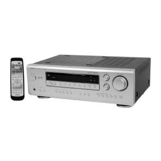
AV SURROUND RECEIVER
September 2000
CONTENTS
SM0102
HTADD1E
HTADD1EBS
HTADD1W
HTADD1WUN
Data
contained
within
this
manual is subject to alteration for
improvement.
Les données fournies dans le présent
manuel d'entretien peuvent faire l'objet
de modifications en vue de perfectionner
le produit.
Die
in
diesem
Wartungshandbuch
enthaltenen Spezifikationen können sich
zwecks Verbesserungen ändern.
Service
Advertisement
Table of Contents

Related Manuals for Hitachi SM0102


Summary of Contents for Hitachi SM0102
-
Page 1: Table Of Contents
SM0102 HTADD1E HTADD1EBS HTADD1W HTADD1WUN SERVICE MANUAL MANUEL D'ENTRETIEN WARTUNGSHANDBUCH CAUTION: Before servicing this chassis, it is important that the service technician read the “Safety Precautions” and “Product Safety Notices” in this service manual. Data contained within this Service manual is subject to alteration for improvement. - Page 2 ALL PRODUCTS CE MARK Before any service is performed on the chassis an 1. HITACHI products may contain the CE mark on isolation transformer should be inserted between the the rating plate indicating that the product power line and the product.
- Page 3 The following precautions should be observed when servicing. Since many parts in the unit have special safety related characteristics, always use genuine HITACHI replacement parts. Especially critical parts in the power circuit block should not be replaced with other makers.
-
Page 4: Specifications
SPECIFICATIONS • Audio section (Power amplifier) Rated output: Front: 60 W + 60 W (8W/ohms, 20 Hz ~ 20 kHz with 0.08 % T.H.D.) Centre: 60 W (8W/ohms, 20 Hz ~ 20 kHz with 0.08 % T.H.D.) Surround: 60 W + 60 W (8W/ohms, 20 Hz ~ 20 kHz with 0.08 % T.H.D.) Output terminals Front:... -
Page 5: Service Points
SERVICE POINTS 1. Removal of Top Cover (a)Remove 4 screws 2 from the rear plate. (b)Remove 2 screws 1 from each side. Top cover Fig. 1 2. Removal of the Rear Plate (a)Remove 23 screws 3 and 1 screw 4 from the rear plate. (b)Remove 5 screws + from the Bottom Chassis. - Page 6 3. Removal of Tuner/DSP/Video/Digital PWB Board (a)Remove the Flat cable Z at the Tuner PWB. (b)Gently pull the Tuner/DSP/Video PWB Board upwards to detach 8 connectors from Main PWB Board. (c)Detach the connector from DSP PWB Board to remove the Digital PWB. Connectors x 8 Flat cable Digital PWB...
- Page 7 8. Removal of Front Panel (a)Invert the Bottom Chassis and remove 4 screws ". (b)Remove the Master Vol. & Bass/Treble Knob before remove the Front panel. 12 x 1 11 x 4 Bottom Chassis Front Panel Bass/Treble Knob Master Vol. Fig.
- Page 8 10. Removal of Foot (a)Remove 4 screws ) to remove foot. 17 x 4 Fig. 7...
-
Page 9: Adjustments
ADJUSTMENTS 1) FM Discriminator Measuring instrument and condition. Input Terminal Output Terminal Measuring Instrument Frequency Adjust Reading FM Antenna * R22 DC Balance Meter 98.1MHz 0±30mV 1kHz, 60 dBµ 22.5kHz dev. DC balance meter 2) Voltage of covering (Reference) Measuring instrument and condition. Band Destination Frequency... - Page 10 3) Idling voltage (No adjustment is needed) Test points Condition a) Front left channel (MAIN PWB) Master volume : --- (min) C522 L501 Temperature : 15 ~ 30°C JP513 Reading (SPEC) 1) POWER ON AFTER ONE MIN. 0.5 ~ 2.0 mV 2) STABLE Æ...
-
Page 11: Wiring Diagram
SM0102 WIRING DIAGRAM... - Page 13 SM0102 TUNER PCB...
- Page 14 SM0102 SURR PCB...
- Page 15 SM0102 DSP PCB...
- Page 16 SM0102 FL PCB...
- Page 17 SM0102 POWER PCB...
- Page 18 SM0102 VIDEO PCB...
- Page 19 SM0102 SPJK PCB...
- Page 20 SM0102 SW-H-P PCB...
- Page 21 SM0102 DIGITAL IN PCB...
-
Page 22: Circuit Diagram
SM0102 MAIN CIRCUIT... - Page 23 SM0102 DISP / TONE CIRCUIT...
- Page 24 SM0102 SURROUND MAIN AMP CIRCUIT...
- Page 25 SM0102 TUNER / VOLUME CIRCUIT...
- Page 26 SM0102 DSP CIRCUIT...
- Page 27 SM0102 POWER SUPPLY / VIDEO CIRCUIT...
-
Page 29: Exploded View
VIDEO P.W.B. POWER CAUTION TRANSFORMER (W/WUN) VOLTAGE SELECTOR (W/WUN) Accessories FL DISP PWB AM LOOP ANTENNA 8T Remote Control EDISON PLUG ADAPTER FM ANT... -
Page 30: Replacement Parts List
THE UPDATED PARTS LIST FOR THIS MODEL IS AVAILABLE ON ESTA... - Page 31 Fax: +46 (0) 8 562 711 13 Tel: +39 02 38073415 Servizio Clienti Email: csgswe@hitachi-eu.com Fax: +39 02 48786381/2 Email: customerservice.italy@hitachi-eu.com HITACHI EUROPE S.A.S HITACHI EUROPE LTD (Norway) AB Lyon Office STRANDVEIEN 18 B.P. 45, 69671 BRON CEDEX 1366 Lysaker FRANCE...