Advertisement
Quick Links
CAUTION:
Beforeservicing this chassis, itisimportantthat the servicetechnician read the"Safety
Precautions"and"ProductSafetyNotices"inthisservicemanual.
ATTENTION:
Avantd'effectuerl'entretienduchâassis,letechniciendoitlireles«Précautionsdesécurité»
etles«Noticesdesécuritéduproduit»présentésdansleprésentmanuel.
VORSICHT:
VorÖffnendesGehäuseshatderService-Ingenieurdie„Sicherheitshinweise"und„Hinweise
zurProduktsicherheit"indiesemWartungshandbuchzulesen.
SPECIFICATIONS...............................................................................................................................................3
SERVICE POINTS..............................................................................................................................................4
ADJUSTMENT.....................................................................................................................................................8
WIRING DIAGRAM.............................................................................................................................................9
PRINTED WIRING BOARD..............................................................................................................................10
BLOCK DIAGRAM.............................................................................................................................................23
SCHEMATIC DIAGRAM....................................................................................................................................25
EXPLODED VIEW.............................................................................................................................................43
REPLACEMENT PARTS LIST..........................................................................................................................47
SPECIFICATIONS AND PARTS ARE SUBJECT TO CHANGE FOR IMPROVEMENT
SERVICE MANUAL
MANUEL D'ENTRETIEN
WARTUNGSHANDBUCH
CONTENTS
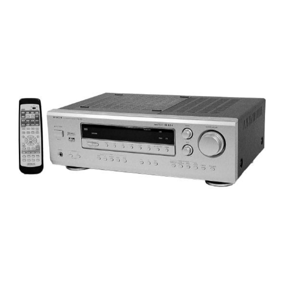
AV SURROUND SYSTEM
September 2000
SM0103
HTADD3E
HTADD3EBS
HTADD3W
HTADD3WUN
HTADD3WAU
Data
contained within
this
manual is subject to alteration for
improvement.
Les données fournies dans le présent
manueld'entretienpeuventfairel'objet
demodificationsenvuedeperfectionner
leproduit.
Die
in
diesem Wartungshandbuch
enthaltenenSpezifikationenkönnensich
zwecksVerbesserungenändern.
Service
Advertisement

Related Manuals for Hitachi SM0103


Summary of Contents for Hitachi SM0103
-
Page 1: Table Of Contents
SM0103 HTADD3E HTADD3EBS HTADD3W HTADD3WUN HTADD3WAU SERVICE MANUAL MANUEL D'ENTRETIEN WARTUNGSHANDBUCH CAUTION: Beforeservicing this chassis, itisimportantthat the servicetechnician read the“Safety Precautions”and“ProductSafetyNotices”inthisservicemanual. Data contained within this Service manual is subject to alteration for improvement. ATTENTION: Les données fournies dans le présent manueld’entretienpeuventfairel’objet... - Page 2 ALL PRODUCTS CE MARK Before any service is performed on the chassis an 1. HITACHI products may contain the CE mark on isolation transformer should be inserted between the the rating plate indicating that the product power line and the product.
- Page 3 The following precautions should be observed when servicing. 1. Since many parts in the unit have special safety-related characteristics, always use genuine Hitachi’s replace- ment parts. Especially critical parts in the power circuit block should not be replaced with other makers. Critical parts are marked with in the circuit diagram and printed wiring board.
-
Page 4: Specifications
HTA-DD3 SPECIFICATIONS • AUDIO SECTION (Power amplifier) For (E, EBS) For (W, WUN, WAU) 80 W + 80 W (6 Ω/ohms, 20 Hz ~ 20 kHz with 0.1 % T.H.D.) 100 W + 100 W (EIAJ, 6 ohms) Front: Rated output: (6 Ω/ohms, 20 Hz ~ 20 kHz with 0.1 % T.H.D.) 100 W (EIAJ, 6 ohms) Centre: 80 W... -
Page 5: Service Points
HTA-DD3 SERVICE POINTS 1. Removal of Top Cover (a) Remove 2 screws 1 from each side. (b) Remove 4 screws 2 from the rear plate. Top cover Fig.1 2. Removal of Rear Plate (a) Remove 28 screws 3 and 1 screw 4 from the rear plate. (b) Remove 5 screws - from the Bottom Chassis. - Page 6 HTA-DD3 3. Removal of Tuner & DSP PWB board (a) Remove the Push Rivet from the Holder (Front) & Holder (Back) then remove the flat cable Z at the Tuner PWB. (b) Remove 1 screw + to detech the shield plate from the bottom chassis. (c) Gently pull the Tuner &...
- Page 7 HTA-DD3 5. Removal of Front Panel (a) Invert the Bottom Chassis and remove 4 screws !. (b) Remove the Master Vol. & Bass/Treble knob before remove the Front panel. 11 x 1 10 x 4 Bottom Chassis Front Panel Bass/Treble Knob Master Vol.
- Page 8 HTA-DD3 7. Removal of Foot (a) Remove 4 screws ( to remove foot. 16 x 4 Fig.7 – 7 –...
-
Page 9: Adjustment
HTA-DD3 A D J U S T M E N T S 1) FM Discriminator Measuring instrument and condition. Input terminal Output terminal Measuring instrument Frequency Adjust Reading FM antenna * R22 DC balance meter 98.1 MHz 0±30mV 1kHz, 60dBu, 22.5kHz dev. -
Page 10: Wiring Diagram
HTA-DD3 WIRING DIAGRAM – 9 –... -
Page 11: Printed Wiring Board
HTA-DD3 PRINTED WIRING BOARD Soldering Side MAIN PWB - 10 -... - Page 12 HTA-DD3 Component Side MAIN PWB - 11 -...
- Page 13 HTA-DD3 Soldering Side Tuner PWB - 12 -...
- Page 14 HTA-DD3 Component Side Tuner PWB - 13 -...
- Page 15 HTA-DD3 Component Side Soldering Side Audio PWB - 14 -...
- Page 16 HTA-DD3 Component Side Soldering Side Relay PWB - 15 -...
- Page 17 HTA-DD3 Component Side Power PWB Digital PWB - 16 - FL PWB...
- Page 18 HTA-DD3 Soldering Side Power Digital PWB FL PWB...
- Page 19 HTA-DD3 Soldering Side Component Side Component PWB...
- Page 20 HTA-DD3 Soldering Side Component Side...
- Page 21 HTA-DD3 Soldering Side S-Video PWB Composit PWB PT2 PWB...
- Page 22 HTA-DD3 Component Side S-Video PWB Composit PWB PT2 PWB...
- Page 23 HTA-DD3 Soldering Side Component Side Phone PWB Phone PWB PT1 PWB PT1 PWB P-SW PWB P-SW PWB...
-
Page 24: Block Diagram
HTA-DD3 B L O C K D I A G R A M – 23 –... - Page 25 HTA-DD3 – 24 –...
-
Page 32: Exploded View
HTA-DD3 EXPLODED VIEW (Cabinet Chassis) S-VIDEO P.W.B. COMPONENT P.W.B. • Nos. are reference Nos. of part list RELAY P.W.B. OUTLET P.W.B. SHIELD PLATE (E/EBS) (W/WUN) P-SW1 P.W.B. VOLTAGE SELECTOR (W/WUN) FL DISP PWB AM LOOP ANTENNA 8T Remote Control EDISON PLUG ADAPTER FM ANT —... - Page 33 THE UPDATED PARTS LIST FOR THIS MODEL IS AVAILABLE ON ESTA...
- Page 34 Fax: +46 (0) 8 562 711 13 Tel: +39 02 38073415 Servizio Clienti Email: csgswe@hitachi-eu.com Fax: +39 02 48786381/2 Email: customerservice.italy@hitachi-eu.com HITACHI EUROPE S.A.S HITACHI EUROPE LTD (Norway) AB Lyon Office STRANDVEIEN 18 B.P. 45, 69671 BRON CEDEX 1366 Lysaker FRANCE...