NETGEAR APS150W, APS250W, APS550W, APS1000W Installation Manual
- Installation instructions (2 pages) ,
- Installation manual (2 pages) ,
- Installation manual (2 pages)
Advertisement
Package Contents

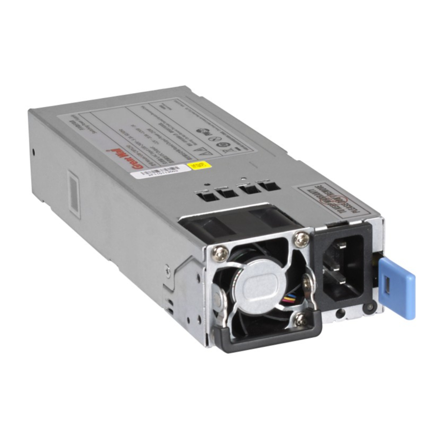
Unit Overview
The following table provides an overview of the power supply units (PSUs) for ProSAFE managed switches and the models in which they are supported.
| PSU Model | Used in Switch Model |
| APS150W | M4300-28G |
| M4300-52G | |
| APS250W | M4300-8X8F |
| M4300-12X12F | |
| M4300-24X24F | |
| APS550W | M4300-28G-POE+ |
| M4300-52G-POE+ | |
| APS1000W | M4300-28G-POE+ |
| M4300-52G-POE+ | |
| M6100-3S | |
| RPS4000v2 |
AC OK LED.
All PSUs provide one AC OK LED. During normal operation, this LED must light green to indicate that valid AC is power is applied to the PSU.
DC OK LED.
Model APS150W also provides one DC OK LED. During normal operation, this LED must light green to indicate that the DC outputs are within regulation limits.
Install an Additional Device
In models with more than one power supply bay, you can install an additional PSU.
- To install an additional PSU:
- Pull out the cover plate from the power module bay in which you want to insert the additional PSU.
- Insert the additional PSU into the power module bay, and gently push the PSU into the bay.
![]()
When inserting the PSU, do not use unnecessary force. Doing so can damage the connectors on the back of the PSU and on the midplane. - Connect the end of the power cord to the power receptacle on the PSU.
- Plug the AC power cord into a power source such as a wall socket or power strip.
When you apply power, both the AC OK LED on the PSU and the switch's Power LED that is associated with the power supply bay light. If these LEDs do not light, make sure that the power cord is plugged in correctly and that the power source is good.

Replace a Device
In models with more than one PSU, the PSUs are hot-pluggable.
- To replace a PSU:
- If your switch functions with a single PSU only, disconnect the power cord from the PSU and let the switch power down.
If your switch functions with more than one PSU, you do not need to power down the switch and you can perform a hot swap. - Remove the PSU from the power module bay by moving the orange release latch to the left and pulling the extraction handle.

- Insert the replacement PSU into the power module bay, and gently push the PSU into the bay until the latch locks.
![]()
When inserting the PSU, do not use unnecessary force. Doing so can damage the connectors on the back of the PSU and on the midplane. - Connect the end of the power cord to the power receptacle on the PSU.
- Plug the AC power cord into a power source such as a wall socket or power strip.
When you apply power, both the AC OK LED on the PSU and the switch's Power LED that is associated with the power supply bay light. If these LEDs do not light, make sure that the power cord is plugged in correctly and that the power source is good.

Device Technical Specifications
The following table provides the technical specifications for the PSUs.
| Specification | APS150W | APS250W | APS550W | APS1000W |
| AC input | 100–27V ~3A 50–60 Hz or 200–240V ~1.5A 50–60 Hz | 100–240V ~3.5–2A 50–60 Hz | 100–240V ~9–4A 50–60 Hz | 100–127V ~9.9A 50–60 Hz or 200–240V ~7.8A 50–60 Hz |
| DC output | +12V 12.5A | +12V 20A +12 VSB 1A | +54V 10.95A +12 VSB 2.08A | 56V 12.12A +12 VSB 1.8A @ 100–127V 56V 17.35A +12 VSB 2.4A @ 200–240V |
| Dimensions (H x W x D) | 1.5 x 2.0 x 7.3 in. (39 x 50.5 x 185 mm) | 1.5 x 2.9 x 7.3 in. (39 x 74 x 185 mm) | 1.64 x 3.6 x 8.65 in. (39.3 x 86.36 x 207.56 mm) | 1.64 x 3.6 x 8.65 in. (39.3 x 86.36 x 207.56 mm) |
| Operating temperature | –5 to 50ºC (23 to 122ºF) | 0 to 50ºC (32 to 122ºF) | 0 to 55ºC (32 to 131ºF) | |
| Operating relative humidity | Up to 95% noncondensing | 5% to 95% noncondensing | ||
| Operating altitude level | Below 5,000 m above sea level | Below 3,000 m above sea level | ||
| Storage temperature | –40 to 70ºC (–40 to 158ºF) | –40 to 85ºC (–40 to 185ºF) | ||
| Storage altitude level | Below 15,000 m above sea level | |||
| Safety compliance |
| |||
| EMC compliance |
| |||
| MTBF | 4,534,733 hrs (~517 years) @ 25ºC | 160,000 hrs (~18.3 years) @ 25ºC | 1,708,756 hrs (~195 years) @ 25ºC | 1,272,908 hrs (~145 years) @ 25ºC |
Support
Thank you for purchasing this NETGEAR product. You can visit www.netgear.com/support to register your product, get help, access the latest downloads and user manuals, and join our community. We recommend that you use only official NETGEAR support resources.
For the current EU Declaration of Conformity, visit http://support.netgear.com/app/answers/detail/a_id/11621/.
For regulatory compliance information, visit http://www.netgear.com/about/regulatory/.
See the regulatory compliance document before connecting the power supply.
NETGEAR, Inc.
350 East Plumeria Drive
San Jose, CA 95134, USA
© NETGEAR, Inc., NETGEAR and the NETGEAR Logo are trademarks of NETGEAR, Inc. Any non‑NETGEAR trademarks are used for reference purposes only.

Documents / Resources
References
NETGEAR Support | NETGEAR
EU Declarations of Conformity | Answer | NETGEAR Support
Regulatory | NETGEAR
Download manual
Here you can download full pdf version of manual, it may contain additional safety instructions, warranty information, FCC rules, etc.
Download NETGEAR APS150W, APS250W, APS550W, APS1000W Installation Manual
Advertisement
Thank you! Your question has been received!


Need Assistance?
Do you have a question about the APS150W that isn't answered in the manual? Leave your question here.