NETGEAR RPS4000v2 Hardware Installation Manual
Redundant power system and power bank
Hide thumbs
Also See for RPS4000v2:
- Hardware installation manual (24 pages) ,
- Installation manual (2 pages)

Related Manuals for NETGEAR RPS4000v2

Summary of Contents for NETGEAR RPS4000v2
- Page 1 Hardware Installation Guide Redundant Power System and Power Bank R P S4 0 00v 2 H ardw are I n stal lat io n Gu i d e NETGEAR, Inc. March 2020 350 East Plumeria Drive 202-12072-01 San Jose, CA 95134, USA...
- Page 2 For regulatory compliance information including the EU Declaration of Conformity, visit https://www.netgear.com/about/regulatory/. See the regulatory compliance document before connecting the power supply. For NETGEAR’s Privacy Policy, visit https://www.netgear.com/about/privacy-policy. By using this device, you are agreeing to NETGEAR’s Terms and Conditions at https://www.netgear.com/about/terms-and-conditions.
- Page 3 Updated support and compliance section. • Safety instructions updated. • Replaced RPS4000 images with updated RPS4000v2 images - Updated images include updated labels. • Updated the “Mode” sections header names: - “Mode one” is now Mode 1: Legacy RPS operation mode on page 18.
-
Page 4: Table Of Contents
RPS4000v2 modes of operation........15... -
Page 5: Chapter 1 Introduction
Introduction The NETGEAR Redundant Power System and Power Bank RPS4000 v2 provides state-of-the-art, high-performance, IEEE-compliant network solutions. This guide describes hardware installation and basic troubleshooting for these managed switches. The RPS can be freestanding or rack-mounted in a wiring closet or an equipment room. For additional information, go to the NETGEAR website at http://www.netgear.com. -
Page 6: Front Panel And Leds
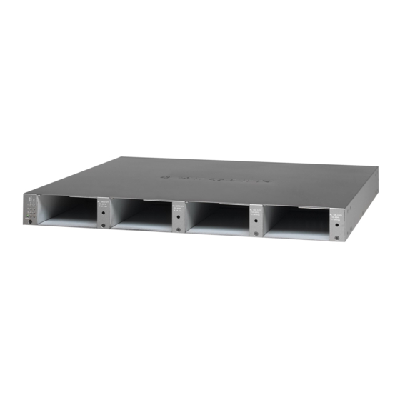
RPS4000v2 Hardware Installation Guide Front panel and LEDs The following figures show the front panel of the RPS4000v2. The front panel contains a pair of power supply unit (PSU) status LEDs for each power module bay. RPS status LEDs APS power module bays Figure 1. -
Page 7: Rear Panel
No power is being supplied to the switch or the switch is not recognized. Rear panel The RPS4000v2 rear panel has four RPS ports, four sets of Type and CS configuration slide selectors, and an AC power receptacle for the RPS4000v2 (AC power cord supplied). RPS port... -
Page 8: Safety Instructions
Any device that is located outdoors and connected to this product must be properly grounded and surge protected. Failure to follow these guidelines can result in damage to your NETGEAR product, which might not be covered by NETGEAR’s warranty, to the extent permissible by applicable law. - Page 9 Depending on your device, use only a supplied power adapter or approved power cable: If your device uses a power adapter: • If you were not provided with a power adapter, contact your local NETGEAR reseller. • The power adapter must be rated for the product and for the voltage and current marked on the product electrical ratings label.
-
Page 10: Chapter 2 Hardware Installation
Hardware Installation This chapter explains how to install the RPS. This chapter contains the following sections: Package contents • Protecting against electrostatic discharge • Unpack the hardware • Installation • Connect equipment to the RPS4000v2 • RPS4000v2 modes of operation •... -
Page 11: Package Contents
RPS4000v2 Hardware Installation Guide Package contents The package contains the following items: • RPS4000v2 • Power cord • Rubber footpads for tabletop installation • Rack-mounting kit Protecting against electrostatic discharge WARNING: Static electricity can harm delicate components inside your system. -
Page 12: Installation
RPS4000v2 Hardware Installation Guide Note: If any item is found missing or damaged, contact your local NETGEAR reseller for replacement. 5. Inspect the products and accessories for damage. Report any damage immediately. Installation Install the equipment in the sequence presented in this section: 1. -
Page 13: Install The Rps
RPS4000v2 Hardware Installation Guide Table 2. Site requirements for RPS location Requirements Operating humidity Install the RPS in a dry area with a maximum relative humidity of 90%, noncondensing. Ventilation Do not restrict airflow by covering or obstructing air inlets on the sides of the RPS. -
Page 14: Check The Installation
If the Power LED does not light, check that the power cable is plugged in correctly and that the power source is good. For help with troubleshooting, see Chapter 3, Troubleshooting. Connect equipment to the RPS4000v2 To connect a device to the RPS: 1. Disconnect the AC power cord from the switch or device. -
Page 15: Rps4000V2 Modes Of Operation
2. Connect one end of the NETGEAR RPS cable to the RPS connector on the switch rear panel. 3. Connect the other end of the NETGEAR RPS cable to the RPS4000v2 rear panel RPS port connector. 4. Reconnect the AC power cord to the switch or device. - Page 16 • The CS selector can be set on or off **** The RPS4000v2 turns off current sharing when two APS1000W AC input ranges are not in same ranges In addition to these settings, be aware of compatibility issues that can cause the RPS4000v2 to power off.
- Page 17 RPS4000v2 Hardware Installation Guide • Both RPS ports are in the same group but not set to the same setting. • The RPS ports do not have their selectors set to the correct Type and CS settings for their respective operation modes, as shown in Table 4, Operation modes.
-
Page 18: Mode 1: Legacy Rps Operation Mode
One RPS cabled to one switch and one APS1000W dedicated to one switch are required to use this mode. If a Type B switch is connected to RPS4000v2 in this mode, the switch will only receive maximum power as indicated in Table 3 on page 16. -
Page 19: Mode 2: Normal Operation Mode
On Type B switches such as the M5300 series switch, each RPS port delivers power from each APS1000W to the connected switches. For each RPS port to provide power, its corresponding APS1000 PSU must be installed in the RPS4000v2 chassis. Figure 6. Normal operation mode diagram... -
Page 20: Mode 3: High Power Operation Mode
Mode 3: High power operation mode This mode supports Type B switches such as the M5300 series switches. RPS ports deliver power to switches when the RPS4000v2 detects a connected Type B switch over the I2C bus. In this mode, the RPS port can provide a maximum 1440W of PoE power to switches when 2 PSUs are present and work well in the same group. -
Page 21: Mode 4: Poe Power N+1 Operation Mode
Mode 4: PoE power N+1 operation mode This mode supports Type B switches such the M5300 series switches. RPS ports deliver power to switches when the RPS4000v2 detects a connected Type B switch over the I2C bus. In this mode, one APS1000W can provide power to 2 RPS ports in the same group. -
Page 22: Mode 5: System Power N+1 Operation Mode
In this mode, an APS1000W can be installed in any bay. If the Type B switch is connected to RPS4000v2 in this mode, the switch will only receive maximum power as indicated in Table 3 on page 16. -
Page 23: Mode 6: Standby Mode
None of the other APS1000W PSUs provide power in this mode. One RPS cable to one switch and one or more APS1000W installed in the RPS4000v2 bays are required to use this mode. Figure 10. Standby mode diagram... -
Page 24: Mode 7: Current Sharing Operation Mode
When ports 1 or 3 do not have switches connected, ports 2 and 4 can provide 1440W of power. Note: RPS Ports 1 and 3 take priority. The RPS4000v2 will cutoff output power to ports 2 and 4 if switches are connected to ports 1 and 3. -
Page 25: Chapter 3 Troubleshooting
Troubleshooting Troubleshooting Chart The following table lists symptoms, causes, and solutions of possible problems. Table 5. Troubleshooting chart Problem Cause Solution Power LED is off. No power is received. Check the power cord connections for the switch at the switch and the connected device. Make sure that all cables used are correct and comply with Ethernet specifications. -
Page 26: Appendix A Technical Specifications
Technical Specifications Technical Specifications Table 6. Technical specifications Feature Description Environment Operating: • Temperature: 32° to 122°F (0° to 50°C) • Humidity: 90% maximum relative humidity, noncondensing • Altitude: 10,000 ft (3,000 m) maximum Storage: • Temperature: – 4° to 158°F (–20° to 70°C) •...