Yamaha DTXPLORER DTLK9 - Electronic Drum Pad Set Manual
- Manuale dell'utente (36 pages) ,
- Owner's manual (2 pages) ,
- Manual (2 pages)
Advertisement
INTRODUCTION
Thank you for purchasing the DTXPLORER Electronic Drum Set by Yamaha. The DTLK9 Pad Set is a special pad set that is supplied with the DTXPLORER. Before using the pads, please read this Owner's Manual thoroughly and use the product in a safe and proper manner. After reading this manual, please keep it in a safe place for future reference.
Inside This Package
Before using the product, make sure that all of the items listed below are present and accounted for. If anything is missing, please contact the dealer from whom you purchased the product.

PRECAUTIONS
Before using, please read this "Owner's Manual" sheet, and use this product in a safe and proper manner.
Especially for children, parents or an instructor should teach the children the proper manner in which to use the device.
* After reading this Owner's Manual, please keep it in a place where it can be accessed by the user at anytime.
To prevent against accidents and injury
Please follow the cautions listed below
 Caution (including danger, or warning). This mark indicates cautions in which you should pay close attention to.
 Acts indicated with this icon are prohibited and should not be attempted.
 If this symbol is ignored and the equipment is used improperly, fatal injury to persons or serious damage could occur. |
 Do not place the rack stand (RS40) on an unstable surface when the pads are attached. Do not place the rack stand (RS40) on an unstable surface when the pads are attached. |
| When the pads are attached to the rack system (RS40), make sure that all nuts and bolts, etc., are tightened firmly. Never loosen the nuts and bolts, etc. suddenly. It may cause pads or rack/stand parts to drop or fall off resulting in injury. |
| Please be watchful when children are in the vicinity of the product so as to prevent injuries from occurring. |
| When setting up the pads, pay close attention to the manner in which the cables are connected, etc. Feet can become entangled in the cables resulting in injury. |
 If this symbol is ignored and the equipment is used improperly, there is a danger of injury to persons handling the equipment, and material damage could occur. |
| Watch your hands, fingers, feet, etc., when assembling the product system or attaching the pads to the rack system (RS40). They can become pinched between parts causing injury. |
| Do not put your hands or feet under the foot pedal (FP6110) or the hi-hat control pedal (HH65) or around their moving parts. Doing so can result in injury. |
| Some of the parts included with the product may have sharp edges or ends (spurs on the HH65 and KP65, etc.). Take care when handling their parts. Not doing so can result in injury. |
* Due to improvements, specifications and appearance are subject to change without notice.
Handling Precautions
- Do not disassemble or alter the product. Doing so may result in damage or deterioration to the product.
- Do not step on or place heavy objects on the product. It may result in damage.
- Do not use or keep the product in places with extremely high temperature (places in direct sunlight, close to a heater, in a closed car, etc.) or damp (bathroom, outside on a rainy day, etc.). It may result in deformation, discoloration, damage or deterioration.
- When connecting or disconnecting the cable, make sure that you hold the plug, not the cable. Also, never place any heavy objects on the cable and never allow any sharp objects to come into contact with the cable. Applying excessive force to the cable may result in damage to the cable such as cutting the wires, etc.
- To clean the product, please wipe with a soft cloth or a damp cloth that been wrung out thoroughly, If the product is soiled, use a neutral detergent on a cloth then wipe with a damp cloth that has been wrung out thoroughly to remove any remaining detergent. Do not use benzine, thinner or alcohol as it may result in discoloration or deformation. Also pay close attention so as not to let the water and detergent come into contact with the cushions used in the product, it may result in deterioration.
- white powdery substance may be present on the backside of the pad's rubber. This powder is a remnant of one of the ingredients found in the rubber and will not cause have any negative impact on the function or performance of the pad. We apologize for the inconvenience but if the powder is present, please follow the instructions above and clean the pad to remove the powder.
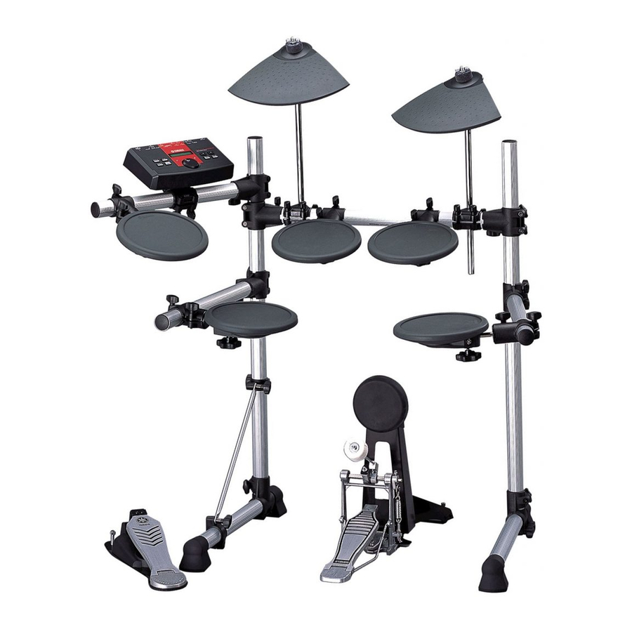
Set up example


- TP65 (Tom Pad)
This pad is used for the system's snare drum, tom toms (x3) and hi-hat. Slide the pad onto the tom holder (hexagonal bar) attached to the rack system (RS40) and firmly tighten the clamp bolt to secure. - PCY65 (Cymbal Pad)
This pad is used for the system's crash and ride cymbals. Place the pad between the two felts and then secure onto the rack system's (RS40) cymbal holder. - HH65 (Hi-Hat Control Pedal)
This pedal is used to control the opening and closing of the hi-hat cymbal. Position the pedal underneath the rack mounted hi-hat cymbal pad (TP65) in a manner that provides both player comfort and pedal stability.
- HH65 Functions
- The hi-hat's closed sound is produced when the pedal on the HH65 is depressed.
- A foot-splash can be produced by quickly pressing and releasing the foot pedal.
- The hi-hat's sound (fully closed, half open, fully open) changes in relation to the foot pedal's position.
NOTE: If the product is set up on a special purpose drum riser, or if damage to the floor is not a concern, extend the pedal's spurs so that their points grip the riser or floor to prevent the HH65 from moving during performance.
NOTE: To prevent damage to the floor, rotate the spurs counter-clockwise so that their tips do not come in contact with the floor.
Adjusting the Pedal Stroke

- The pedal stroke can be adjusted to fit your particular playing needs.
- Change the position of the adjustment bolt to adjust the pedal's stroke.
- The stroke increases as the adjustment bolt is positioned higher and decreases as the adjustment bolt is positioned lower.
- Use the supplied drum key to loosen the square tightening bolt and adjust its position, then firmly tighten the square bolt to secure.
- KP65 (Kick Pad)
This pad is used as the system's bass drum.
 Overview")
- Assemble the KP65. As shown in the illustration, remove the base attachment wing bolts, washers and spring washers (4 each) that are attached to the main body, and use those to attach the base to the main body. Only loosely tighten the wing bolts in this step.
- Attach the foot pedal (FP6110, shown below) to theKP65. When attaching the pedal, make sure that the pedal's hoop clamp firmly clamps onto the ridge that runs across the front of the KP65's base. Rotate the T-handled bolt to the left to loosen the hoop clamp and to the right to tighten.
- Adjust the base's position so that the DP65 pad'splaying surface is vertical when the foot pedal is attached, and make sure that the KP65 is stable when the beater hits the pad. After the position is determined, firmly tighten the wing bolts to secure.
- Adjust the pedal's position and the shaft length ofthe beater so that the foot pedal's beater hits in the center of the kick pad.
NOTE: The KP65 can be configured with a double foot pedal (Yamaha DFP7210, etc., sold separately). When using a double foot pedal configuration, adjust the pedal's position and the length of the beaters so that the space between the two beaters is positioned in the center of the head.
NOTE: If the product is set up on a special purpose drum riser, or if damage to the floor is not a concern, extend the foot pedal's spurs so that their points grip the riser or floor to prevent the KP65 from moving during performance.
- FP6110 (Foot Pedal)
The FP6110 foot pedal attaches to the KP65.
First, assemble the pedal as shown in the illustration.
 assembly")
 assembly")
- Insert the foot board stabilizer rods into the holeson the frame as shown in the illustration.
- Attach the beater to the pedal as shown in the illus-tration, and use the beater fixing bolt to secure the beater in a suitable position.
If necessary, carry out the adjustments described below.
- Adjusting the Beater Angle
Use a drum key (not supplied) to loosen the beater angle adjustment bolt and adjust the angle of the beater, then secure. - Adjusting the Spring Tension
The recoil tension of the foot board is adjustable.- To increase spring tension, loosen nut A then tighten nut B shown in the illustration.
- To decrease spring tension, loosen nut B shown in the illustration. Once the desired spring tension has been obtained, firmly tighten nuts A and B.
Connections
Use the supplied 9ch snake cable to connect the pad's OUTPUTs to the pad inputs on the DTXPLORER Drum Trigger Module. Connect the cable's L-shaped plugs to the pads.

If the pads are positioned as shown in the illustration in the "Setup" section, follow the labels on 9ch snake cable's plugs (SNARE, TOM1, etc.) and connect the cable's plugs to their corresponding pads. If a setup other than the one shown above is used, connect the plugs to the pads according to the cable's length.

Adjusting the Output Level
(LEVEL): PCY65/KP65

The PCY65 and KP65 are equipped with level adjustment knobs for adjusting the trigger output level. The pad's output level should be adjusted in regard to how hard you hit the pad when playing and the dynamic level which you require. Rotate the level adjustment knob to the right (+) to increase the output level, and to the left to decrease output level.
NOTE: Adjust the level so that the DTXPLORER'S input level display registers 90-95% when you play ff (fortissimo: the loudest playing level). Please refer to the Owner's Manual that came with the DTXPLORER for more information. Too high of an output level setting will result in a narrow dynamic range (the difference between loud and soft) or may produce trouble such as double triggers (a single hit produces multiple sounds), etc.
: Do not put excessive pressure on the level adjustment knob, it may result in damage.
Connecting an External Pad: KP65

The KP65's external pad input jack can be used to connect an additional pad to the system. In this case, the external pad's trigger signal is sent to the DTXPLORER's Input 9 (the KP65 is connected to Input 8).
NOTE: Any of the pads in the DTX series can be used as an external pad however, pads equipped with rim switches (TP65S, PCY65S, etc.) will not be able to produce sounds from their rims. Functions that utilize the rim switch (choke, mute) are also not available.
Specifications
- PCY65
- Dimensions 312(W) X 245(D) X 46.5(H) mm
- Weight 620g
- Sensor System Trigger Sensor (Piezo) x 1
- Output Jack Standard Monaural Phone Jack
- HH65
- Dimensions 142mm (W) X 398mm (D) X 104mm (H)
- Weight 1.5Kg
- Sensor System Continuous Switch x1
- Output Jack Standard Stereo Phone Jack
- TP65
- Dimensions 220(diameter) X 61(H) (excluding the clamp bolt)
- Weight 980g (including the clamp bolt)
- Sensor System Trigger Sensor (piezo-electric) x1
- Output Jack Standard Monaural Phone Jack
- KP65
- Dimensions 233(W) x 271(D) x 416(H) mm (When Assembled)
- Weigh 2.7kg
- Sensor System Trigger Sensor (Piezo) x 1
- Input Jack Standard Monaural Phone Jack
- Output Jack Standard Stereo Phone Jack
- FP6110
- Dimensions 138(W) x 329(D) x 210(H) mm (when assembled: excludes beater)
- Weight 1.2kg (includes beater)
- Drive System Belt
- Beater Felt
* Improvements may result in a change in the specifications and/or design of the product without notice.
Replacing Worn Out Parts
- After extended use, some of the product's parts will wear out or their quality will deteriorate (pad rubber, cushion material used inside the pads, switches, jacks, etc.). The life of these parts will vary depending upon the circumstances under which the product is used.
- Please contact the dealer from whom you purchased the product about replacing worn parts.
Troubleshooting
If you experience any problems when using the pads that came with the set, such as sound not being produced, etc., please carefully read the Owner's Manual that came with the DTXPLORER, and check the connections and settings before requesting repair. If a solution to the problem cannot be found and the problem persists, please contact the dealer from whom you purchased the product.

Documents / ResourcesDownload manual
Here you can download full pdf version of manual, it may contain additional safety instructions, warranty information, FCC rules, etc.
Download Yamaha DTXPLORER DTLK9 - Electronic Drum Pad Set Manual
Advertisement
Thank you! Your question has been received!


Need Assistance?
Do you have a question about the DTXPLORER that isn't answered in the manual? Leave your question here.