Hitachi RPC-5.0FSR Operation Manual
Inverter-driven multi-split system heat pump air conditioners, ceiling
Hide thumbs
Also See for RPC-5.0FSR:
- Technical catalogue (88 pages) ,
- Installation & maintenance manual (52 pages) ,
- Installation & operation manua (588 pages)
Table of Contents
Advertisement
Quick Links
Operation
Manual
INVERTER-DRIVEN
MULTI-SPLIT SYSTEM
HEAT PUMP
AIR CONDITIONERS
Type
RPC-1.5FSR
RPC-2.0FSR
RPC-2.5FSR
Ceiling
RPC-3.0FSR
RPC-4.0FSR
RPC-5.0FSR
RPC-6.0FSR
IMPORTANT:
READ AND UNDERSTAND
THIS MANUAL BEFORE
USING THIS HEAT PUMP
AIR CONDITIONERS.
KEEP THIS MANUAL FOR
FUTURE REFERENCE.
Model
A10762290A
Advertisement
Table of Contents

Related Manuals for Hitachi RPC-5.0FSR


Summary of Contents for Hitachi RPC-5.0FSR
- Page 1 Operation Manual INVERTER-DRIVEN MULTI-SPLIT SYSTEM HEAT PUMP AIR CONDITIONERS Type Model RPC-1.5FSR RPC-2.0FSR RPC-2.5FSR Ceiling RPC-3.0FSR RPC-4.0FSR RPC-5.0FSR RPC-6.0FSR IMPORTANT: READ AND UNDERSTAND THIS MANUAL BEFORE USING THIS HEAT PUMP AIR CONDITIONERS. KEEP THIS MANUAL FOR FUTURE REFERENCE. A10762290A...
- Page 3 IMPORTANT NOTICE ● HITACHI pursues a policy of continuing improvement in design and performance of products. The right is therefore reserved to vary specifications without notice. ● HITACHI cannot anticipate every possible circumstance that might involve a potential hazard. ● This heat pump air conditioner is designed for standard air conditioning only. Do not use this heat pump air conditioner for other purpose such as drying clothes, refrigerating foods or for any other cooling or heating process. ● Do not install the unit in the following places. It may cause a fire, deformation, corrosion or failure. * Places where a fire, oil, steam or powder may enter directly to the unit such as right above a kitchen, etc. * Places where oil (including machinery oil) may be present in quantities. * Places where a lot of sulfide gas drifts such as in a hot spring. * Places where inflammable gas may generate or flow. * Places where strong salty wind blows such as coast regions. * Places with an atmosphere of acidity or alkalinity. * Places where gas from festering trash, etc. may generate. ● Do not install the unit in the place where silicon gas drifts. If the silicon gas attaches to the surface of heat exchanger, the fin surface repels water. As a result, drain water splashes outside of the drain pan and splashed water runs inside of electrical box. In the end, water leakage or electrical devices failure may occur. ● Pay attention to the following points when the unit is installed in a hospital or other facilities where an electromagnetic wave generates from a medical equipment. * Do not install the unit in the place where an electromagnetic wave is directly radiated to the electrical box, controller cable or wired controller. * Install the unit at least 3 meters away from an electromagnetic wave such as a radio. ● Do not install the unit in the place where the breeze directly catches animals and plants. It could adversely affect animals and plants. ● The installer and system specialist shall secure safety against the refrigerant leakage according to local regulations or standards. The following standards may be applicable, if local regulations are not available. International Organization for Standardization, ISO5149 or European Standard, EN378 or Japan Standard, KHKS0010. ● No part of this manual may be reproduced without written permission.
- Page 4 C DB/15 C WB Cooling Operation Outdoor C DB * C DB * Indoor C DB C DB Heating Operation Outdoor C WB * C WB * DB: Dry Bulb, WB: Wet Bulb * The temperature may change depending on the outdoor unit. This manual should be considered as a permanent part of the air conditioning equipment and should remain with the air conditioning equipment. CHECKING PRODUCT RECEIVED ● Upon receiving this product, inspect it for any shipping damage. Claims for damage, either apparent or concealed, should be filed immediately with the shipping company. ● Check the model number, electrical characteristics (power supply, voltage and frequency) and accessories to determine if they are correct. The standard utilization of the unit shall be explained in these instructions. Therefore, the utilization of the unit other than those indicated in these instructions is not recommended. Please contact your local agent, as the occasion arises. HITACHI’s liability shall not cover defects arising from the alteration performed by a customer without HITACHI’s consent in a written form. A10762290A...
-
Page 5: Table Of Contents
TABLE OF CONTENTS 1. Safety Summary .............................1 2. Before Operation .............................6 2.1 Efficient Use of Indoor Unit ........................6 2.2 Efficient Use of Cooling and Heating ......................6 3. Name of Parts and Indication of Safety Consideration ...................7 3.1 Indoor Unit ..............................7 3.2 Wired Controller .............................8 4. Operation Method ............................9 5. Setting Method ..............................9 6. Operation ................................9 7. Operation Lock ..............................9 8. Menu Operation ..............................9 9. Motion Sensor ...............................10 9.1 Function ..............................10 9.2 Details for Motion Sensor Control ......................10 9.3 Descriptions for Setting Items ...................... -
Page 7: Safety Summary
Safety Summary < Signal Words > ● Signal words are used to identify levels of hazard seriousness. Definitions for identifying hazard levels are provided below with their respective signal words. DANGER : DANGER indicates a hazardous situation which, if not avoided, will result in death or serious injury. WARNING : WARNING indicates a hazardous situation which, if not avoided, could result in death or serious injury. CAUTION : CAUTION, used with the safety alert symbol, indicates a hazardous situation which, if not avoided, could result in minor or moderate injury. NOTICE : NOTICE is used to address practices not related to personal injury. NOTE : NOTE is useful information for operation and/or maintenance. A10762290A... - Page 8 DANGER ● Do not perform the installation work, refrigerant piping work, drain pump, drain piping and electrical wiring connection without referring to our installation manual. If the instructions are not followed, it may result in a water leakage, electric shock or a fire. ● This machine uses refrigerant R410A or refrigerant R32. The type of enclosed refrigerant is described in the specification nameplate and caution nameplate attached to the outdoor unit. When installing, repairing, or relocating, do not mix substances other than the refrigerant described on the specification nameplate or caution nameplate attached to the outdoor unit. Also, do not mix refrigerant R410A and refrigerant R32. Entering non-designated refrigerants, air, oxygen, flammable substances such as propane or alcohol may cause explosion, fire or injury. ● Do not pour water into the indoor unit. These products are equipped with electrical parts. If poured, it will cause a serious electrical shock. ● Do not open the service cover for the indoor or outdoor unit without turning OFF the main power supply. ● Do not touch or adjust safety devices inside the indoor unit or outdoor unit. If these devices are touched or readjusted, it may cause a serious accident. ● Refrigerant leakage can cause difficulty with breathing due to insufficient air. Turn OFF the main switch, extinguish any naked flames and contact your service contractor, if refrigerant leakage occurs. ● Make sure that a refrigerant leak test has been performed. Refrigerant (Fluorocarbon or Difluoromethane) for this unit is non-toxic, and odorless. If the refrigerant should somehow escape and come into contact with flame, toxic gas will form. This gas is heavier than air and will settle near floor areas and spread where it can cause suffocation to those nearby. In addition, difluoromethane is flammable and can cause fire. ● The installer and system specialist shall secure safety against refrigerant leakage according to local regulations or standards. ● Use an ELB (Earth Leakage Breaker). In the event of fault, there is danger of an electric shock or a fire if it is not used. ● Do not install the outdoor unit where there is high level of oil mist, flammable gases, salty air or harmful gases such as sulfur. ● For installation, firmly connect the refrigerant pipe before the compressor starts operating. For maintenance, relocation and disposal, remove the refrigerant pipe after the compressor stops.
- Page 9 WARNING ● The installation work shall be performed by the specialist installer. If it is not completed, it may cause a water leakage, an electric shock, a fire or falling down the unit. ● Perform the electrical work according to Installation Manual and all the relevant regulation and standards. If the instructions are not followed, an electrical shock and fire may occur due to insufficient capacity and inadequate performance. ● The electrical wiring work must be performed by authorized installers. If not performing the electrical work completely or a capacity shortage of the power circuit, it may cause an electric shock or a fire. Additionally, if the earth wire is disconnected, it may cause an electric shock. Contact the authorized installer and connect the earth wiring. ● If the circuit breaker or fuse is often activated, stop the system and contact your service contractor. ● Check that the ground wire is securely connected. If the unit is not correctly grounded, it will lead electric shock. Do not connect the ground wiring to a gas piping, water piping, lighting conductor or ground wiring for telephone. ● Use specified cables between units and choose the cables correctly. If not, an electrical shock or fire may occur. ● Ensure that the wiring terminals are tightened securely with the specified torques. If not, generating fire or an electrical shock at the terminal connection part may occur. ● Connect a fuse of specified capacity. ● Protect the wires, electrical parts, etc. from rats or other small animals. If not protected, rats may gnaw at unprotected parts and which may lead to a fire. ● Fix the cables securely. External forces on the terminals could lead to a fire. ● Provide a sufficiently strong foundation. If not, the unit may fall down and it may lead to injuries. ● If the indoor unit is installed in a small room and the refrigerant gas leakage occurs, the leaked refrigerant gas fills the room and it may cause suffocation. Do not exceed the maximum permissible concentration of the refrigerant gas in the room. Consult with distributor for countermeasure such a ventilation system, etc. ● Before performing any brazing work, check to ensure that there is no flammable material around.
- Page 10 ● When the indoor unit is operated with heating appliances, ventilate a room sufficiently. If not, it may cause suffocation. ● Turn OFF the main power source immediately if the safety device is frequently activated or the main power source switch does not work. If not, it may cause an electric shock, a fire or explosion because there are possibilities of the electrical leakage or overcurrent, etc. Contact your distributor or contractor. ● If abnormality (burnt odor, etc.) occurs, stop the operation and turn OFF the main power source immediately. If not, it may cause breakage of the product, an electric shock or a fire. Contact your distributor or contractor. ● Do not operate the indoor unit without the electrical box cover and the air inlet grille. It is unusually dangerous that the indoor fan and electrical parts are exposed. In addition, it may cause an electric shock due to touch the electrical parts. ● When the air conditioner is necessary to be repaired or relocated, contact your distributor or contractor. If the repair and the installation are not completed, it may cause an electric shock or a fire. ● Do not perform the installation work, the refrigerant piping work, the drain pump, the drain piping and electrical wiring connection without tuning OFF the main power source. It may cause an electric shock or injury. ● Perform the maintenance work with stable footing. If not, it may cause falling or injury. ● Do not spray water or detergent to the indoor unit when performing the maintenance work. It may cause an electric shock or a fire by electrical short-circuit. ● Protect securely the electrical parts and connectors not to splash water when performing the maintenance work. If not, it may cause an electric shock or a fire by electrical short-circuit. ● The inside piping charged refrigerant is high pressure. Perform securely the refrigerant piping work by the authorized installer. If not, it may cause a serious accident. NOTE Additional safety information for R32 refrigerant air conditioner and heat pump according to IEC 60335-2-40: 2018.
- Page 11 CAUTION ● Do not step or put any material on the product. ● Do not put any foreign material on the unit or inside the unit. ● Do not turn OFF the main power source of the indoor unit during the season of heating and cooling. The water can not be discharged forcedly so that overflows from the drain pan. As the result, the floor and the ceiling surface are smudged. ● Hold the air filter and the air inlet grille by hand when attaching (removing). If not, it may cause falling or injury. ● Do not blow cold air to a person for a long time or overcool. It may cause deterioration of physical condition and health impairment. ● Do not handle the unit by one person. Although the unit may be packed by polypropylene band, do not use it for transportation. If the unit is handled by hand, the fin surface of heat exchanger causes a cut. NOTICE ● Do not install the indoor unit, outdoor unit, wired controller and cable within approximately 3 meters from strong electromagnetic wave radiators such as medical equipments. ● Supply electrical power to the system to energize the oil heater for 12 hours before startup after a long shutdown. ● Make sure that the outdoor unit is not covered with snow or ice, before operation. ● In some cases, the packaged air conditioner may not be operated normally under the following cases. * In case that electrical power for the packaged air conditioner is supplied from the same power transformer as the device*. * In case that the power source wires for the device* and the packaged air conditioner are located close to each other. Device*: (Ex) Lift, container crane, rectifier for electric railway, inverter power device, arc furnace, electric furnace, large-sized induction motor and large-sized switch. It consumes a large quantity of electrical power. Regarding the cases mentioned above, surge voltage may be inducted in the power supply wiring for the packaged air conditioner due to a rapid change in power consumption of the device and an activation of switch.
-
Page 12: Before Operation
Before Operation 2.1 Efficient Use of Indoor Unit ● Do not leave a window or a door open. The operating efficiency will be decreased. It may cause dew condensation of the indoor unit. (Ventilate a room sufficiently too.) ● Attach a curtain or a blind to a window. Direct sunlight is prevented and the cooling efficiency will be increased. ● Do not use heating appliances during the cooling operation as possible. The cooling efficiency will be decreased. It may cause dew condensation and dropping dew. ● Use a circulator if warm air stays around ceiling. -
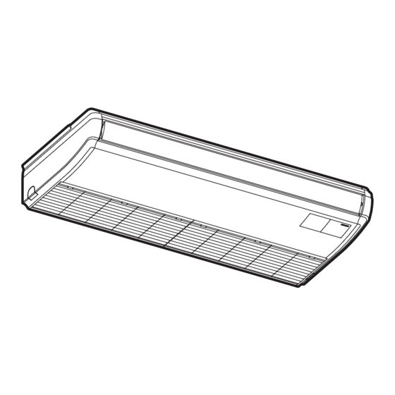
Page 13: Name Of Parts And Indication Of Safety Consideration
Name of Parts and Indication of Safety Consideration The safety considerations are indicated on the indoor unit in order to be used safety. Read and understand this manual before using the indoor unit. 3.1 Indoor Unit WARNING Label Indoor Unit Air Outlet Louver Motion Sensor (Option) Air Inlet Grille (The air filter is attached Indication Place inside.) for Indoor Unit Model ● It is indicated in the specification plate attached at the fan casing. (Check it by opening the air inlet Wired Controller grille.) (Option, The operating condition is visible by the LCD indication.) -
Page 14: Wired Controller
3.2 Wired Controller Model: PC-ARF1 (Optional) The example below references the control panel and all adjustable settings. The wired controller display may be Display Part different during actual operation. Fan Speed Indicator Swing Louver Indicator Schedule Timer Indicator It is indicated when the schedule Avoid Air and Receive timer function is set. (*) Operation Mode Indicator Indicator Operation Lock Indicator It is only for the lower cover The indications of with motion sensor. (*) It is indicated when the operation “HEAT” and “AUTO” are lock function is set. (*) indicated only for the heat pump type models. Filter Sign Indicator FLTR Room Name It is indicated at the set period for... -
Page 15: Operation Method
Operation Method Refer to the operation manual of PC-ARF1. Setting Method ● Swing Louver Direction during Heating Operation Refer to the operation manual of PC-ARF1. * When the heating operation starts ● Adjusting Vertical Deflector * When the defrost operation starts The vertical deflectors which consist 3 sets of * When thermo-controller activates deflector are connected by the connecting rod. Adjust the vertical deflectors by hand to the required direction. To adjust them, stop swinging the louver during the operation. The louver angle is fixed horizontally. Louver Connecting Rod Horizontal Vertical Deflector 1 Set When the discharge temperature is higher than 30 C, the louver angle is ● Automatic Setting of Louver automatically returned to the setting The swing louver is stopped and moved by condition. controlling the wired controller. When “Stop” switch is pressed from the wired CAUTION controller, the swing louver will be closed automatically and the operation is stopped. -
Page 16: Motion Sensor
Motion Sensor ● If the function “Prohibiting operation by wired controller” is used from the centralized controller, This setting is available only for the motion sensor select the command “ON” or “Stand-by” in “If kit. absent” at the motion sensor control setting. If “OFF” is selected, the motion sensor control 9.1 Function can not be performed correctly as follows. ● The motion sensor detects a human activity by * In the case that “OFF” is selected in the the change of the infrared light. motion sensor control setting and “Prohibiting This function saves the air conditioning capacity operation by wired controller” (for all items) is (adjusting the set temperature, the air flow set by the centralized controller, the operation volume and the air flow direction) automatically will not be stopped even if the motion sensor depending on a situation. control function changes to the stoppage ● The operation after the motion sensor detects as condition. absence can be selected from “ON”, “Stand-by” * In the case that “OFF” is selected in the or “OFF” on the wired controller with the capacity motion sensor control setting and “Prohibiting saving. operation by wired controller” (for part of items) is set by the centralized controller, the indoor unit operation can not be restarted from the centralized controller although the operation can be stopped under the stoppage ● Do not use the motion sensor function when a condition by the motion sensor control... -
Page 17: Descriptions For Setting Items
9.3 Descriptions for Setting Items 9.4 Setting of Motion Sensor ● Motion Sensor Setting (1) Press “Menu”. The operation mode for activations for function Select “Motion Sensor Setting” from the can be selected as follows: menu by pressing “ ” or “ ” and press “OK”. * ALL MODES: Function is available when the operation mode Menu is “COOL”, “DRY”, “HEAT” or “FAN”. * COOL+DRY: Back/Help 15:10(Fri) Menu Individual Louver Setting Function is available when the operation mode Louver Open/Close is “COOL”, “DRY” or “FAN”. VENTI * HEAT: Menu Total Heat Exchanger SET Motion Sensor Setting Function is available when the operation mode Sel. -
Page 18: Frostwash
(5) Press “ ” or “ ” and select “If absent”. (9) Press “OK” after the setting is completed. The confirmation screen will be displayed. Select “Yes” by pressing “ ” or “ ” and Motion Sensor Setting press “OK”. The motion sensor setting will Sensor Menu ALL MODES be confirmed and the screen will return to the If absent normal mode (operation mode indication). Check interval 30min Back/Help Sel. Adj. Entr Back Rtrn Motion Sensor Setting Menu Save changes in motion sensor setting? (6) The display is switched “ON”, “Stand-by” and Back/Help “OFF” in order by pressing “... -
Page 19: Other Indications
10. Other Indications 10.1 In Normal Condition 10.1.1 Central Control 10.1.3 Defrost "Defrost" is turned ON and the indoor fan stops • When remote control operation is restricted during defrosting operation. The louver is fixed in (all functions) a horizontal position. “Central Control” and “ ” are turned ON. If the remote control restriction is set from the central controller, the settings for RUN, Operation Mode, Temperature Setting, Fan Speed and Louver will not be accessible from the controller. Turned ON • Operation Stoppage during Defrosting Operation If the unit operation is stopped during defrosting operation, the operation continues with the RUN Turned ON indicator (Green) turned OFF. The operation stops after defrosting operation. • When remote control operation is restricted (some functions) “ ” is turned ON. The function operation which is restricted from the central controller cannot be set. 10.1.4 Operation Control • Supplying Main Electrical Power “Preheating” is turned ON at power-on. -
Page 20: Cold Draft Control During Cooling Operation
• Different Operation Mode When the operation mode set by the wired controller is different from the outdoor unit ● The “Control Cool Air” function may not have operation mode, the actual operation mode much effect depending on the operating flashes on the LCD. conditions of the outdoor unit. (except for the heat recovery system models) ● In case one outdoor unit is connected to multiple The current operation mode and the message indoor units and the rate of these indoor units “Other remote are in HEAT setting” will be which are equipped with the “Control Cool Air” flashing. function is low, this function may not have much of an effect. ● When this function is set, it may take a few minutes to cool the entire room. ● While this function is activated, “Cold draft rest.” is displayed on the LCD control panel of the wired controller. Flashing Meeting Room MODE SPEED LOUV. TEMP The above display shows the case that Avoid AUTO the cooling mode is set from the wired controller while actual operation mode of the outdoor unit is heating. Cold draft rest. LOUV. -
Page 21: Setback Operation
11. Automatic Control A setback operation requires extra settings. Refer to the “Installation & Maintenance Manual” The system is equipped with the following for the wired controller and the “Service Manual” functions. for details. NOTE Except in the case of a long period of shutdown, 10.1.7 Setback Operation keep the main power switch ON. The drain Setback operation is mainly to sustain a comfort discharge mechanism is operated if the drain room air temperature while occupants are out of level is higher than the setting. the room. If the setback operation is enabled, the setpoint is ● Three Minute Guard (Enforced Stoppage) adjusted for setback. This function is utilized to protect the During this time, “Setback“ is displayed on the compressor. When the function is valid, the LCD. compressor does not operate the unit for at least Refer to the “Installation & Maintenance Manual” 3 minutes after it stops operating, with the RUN for the wired controller and the “Service Manual” indicator turned ON. The operation restarts for details. automatically after 3 minutes. ● Three Minute Guard (Enforced Operation) Meeting Room This function is utilized to protect the MODE... -
Page 22: Simultaneous Operation
13. Maintenance NOTE WARNING ● This air conditioner is used hot air circulation system for the heating operation. ● Turn OFF the power source before the If the air conditioning room is large or the room maintenance work. If not, it may cause a fire temperature is excessively low, it takes time to or an electric shock. warm the whole room. “HOT-START” will be turned OFF after heating the room. ● Perform the maintenance work with stable footing. If not, it may cause falling or injury. ● “HOT-START” may by displayed during or right after the defrosting operation. It is activated to CAUTION... - Page 23 (2) Remove the air filter. (6) Reset the filter sign. Push the air filter toward arrow direction to unhook it from the air inlet grille, and remove NOTE the air filter. If the accumulated time of filter cleaning is not got Upper Side to setting time, the indication “ ” is turned ON and “Setting Disabled” will be displayed. Catch • Press “Menu”. Select “Reset Filter Sign Time” from the menu Lower Side and press “OK”. The confirmation screen will be displayed. Air Filter Lift up the air filter. Catch Menu 15:10(Fri) Simple Timer Reset Filter Sign Time Operation Schedule (3) Clean the air filter.
-
Page 24: Removing, Attaching And Cleaning Air Inlet Grille
13.1.2 Removing, Attaching and Cleaning Air Inlet Grille • While the air inlet grille is being opened, Wipe the air inlet grille by a soft cloth which is depress the knobs of hinge ( ), push the soaked in lukewarm water and squeezed. air inlet grille toward arrow direction ( ) and remove the air inlet grille. Use a soft cloth to clean the air inlet grille, the air Hinge outlet and the service cover. If benzine, thinner or detergent (with surfactant) is used to clean, the Push resin part may be changed color or deformed. In Depress the knob of Depress addition, pay attention that the parts around the air hinge and push the air inlet grille forward. outlet (louver, guide, etc.) may be damaged if an excessive force is applied. (3) Clean the air inlet grille. The air inlet grille can be removed and cleaned. (4) Attach the air inlet grille. (1) Open the air inlet grille. * Attach the air inlet grille in the reverse Press and slide the cover of the air inlet grille procedure for removing. -
Page 25: Troubleshooting
14. Troubleshooting 14.1 This is Not Abnormal Phenomenon Cause and Action All indication lamps on the The micro-computer is activated to protect the wired controller are turned device from electromagnetic waves. Restart the OFF. operation. The operation is stopped automatically because the motion sensor is set as “If absent: OFF” and “Motion Sensor ON” is turned Operation Stopped it detects as absence for a period of time. (All the ON on the wired controller. indoor units connected to the same wired controller are stopped.) Restart the operation. If the instantaneous power After Power Failure failure is within 2 seconds, the operation restarts automatically. White Steam This might occur during the defrosting operation in During Heating Operation from Indoor Unit the heating operation. White Smoke At Beginning of Heating This might occur when dust attached to the heat from Indoor Unit Operation Season exchanger has been dried. -
Page 26: Before Contact
14.2 Before Contact Check the items before contacting a contractor. Trouble Checking Point Action Check that the main power Turn ON the main power source for the air source is turned ON. conditioner. Check that the fuse is not Operation Unavailable Replace the fuse or reset the circuit breaker. blown out or the circuit If the trouble recurs, contact your contractor or breaker of main power source distributor. is not tripped. Check that the air inlet and outlet of the outdoor unit are Cooling Remove objects covering the air inlet and outlet. not covered with a paper, a vinyl or other objects. Immediate Check that there are any shutdown after obstacles preventing the air start-up flow near the air inlet and Heating Remove the obstacles preventing the air flow. outlet of the outdoor unit. Check that the outlet air is not short-circuited to the air inlet. Check that the operation If the fan mode is selected, switch the operation mode is appropriate. -
Page 27: Contact Distributor
14.3 Contact Distributor If the problem is not resolved even after checking the previous items or if other troubles not mentioned in the previous pages occur, stop using the product and contact your distributor or contractor. WARNING If abnormality (burnt odor, etc.) occurs, stop the operation and turn OFF the main power source immediately. If not, it may cause breakage of the product, an electric shock or a fire. Contact your distributor or contractor. Trouble Action before Contact Protection devices (fuses, breakers, and ELB's) activate... -
Page 28: Alarm Code
Protection Abnormality of Inverter Fin High Pressure Sensor Failure Temperature Abnormality of Detection for Fan Motor Outdoor Air Thermistor Failure Position Sensor on Outdoor Unit Discharge Gas Thermistor Failure Outdoor Fan Activation of Fan Controller Protection Evaporating Thermistor Failure Abnormality of Fan Controller Low Pressure Sensor Failure Incorrect Setting of Unit Model System Incorrect Capacity Setting of Incorrect Setting of Unit and Outdoor Unit and Indoor Unit Refrigerant Cycle No. System Incorrect Setting of Other Indoor Unit Compressor Compressor Protection Alarm Number The End © 2020 Hitachi-Johnson Controls Air Conditioning, Inc. A10762290A, 2020 Printed in Japan...