Table of Contents

Related Manuals for Zanussi ZPAC9002


Summary of Contents for Zanussi ZPAC9002
- Page 1 9000/11000 BTU Portable Air Conditioner Model Number: ZPAC9002/11001 220-240V AC 50Hz 0330 1230 597 For Customer Services & Spare Parts please call www.zanussiheatingandcooling.uk Or visit us at PLEASE RETAIN FOR FUTURE REFERENCE...
-
Page 2: Table Of Contents
CONTENTS Page(s) Safety Instructions and Electrical Safety 3 - 5 Feature Diagram Control Panel Diagram Installing your Air Conditioner 8 - 10 Display Screen Diagram Using your Air Conditioner 12 - 20 Draining your Air Conditioner 21 - 22 Cleaning your Air Conditioner 23 - 24 Start/End of Season Operations 25 - 26... -
Page 3: Safety Instructions And Electrical Safety
Safety Instructions Important note: Please read this booklet before installing and switching on this appliance. The manufacturer assumes no responsibility for incorrect installation and usage as described in this booklet. • This model uses natural refrigerant gas as part of its cooling system. This gas is known as R290 (Propane) and is environmentally friendly but can be combustible. - Page 4 Safety Instructions • The appliance must be placed in an area without any continuous sources of ignition (for example: open flames, gas or electrical appliances in operation). • R290/R32 is a refrigerant gas that complies with the European directives on the environment.
- Page 5 Electrical Safety THIS APPLIANCE MUST BE PLUGGED INTO AN EARTHED SOCKET • Before switching on, make sure that the voltage of your electricity supply is the same as that indicated on the rating plate. This product is designed to operate on 220 –...
-
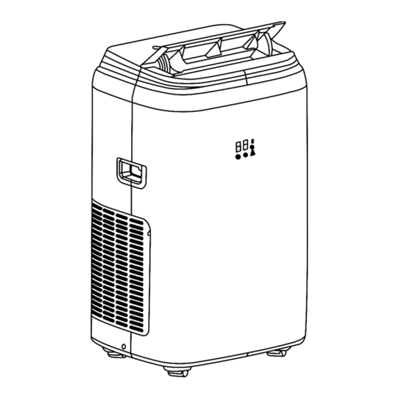
Page 6: Feature Diagram
FEATURE DIAGRAM Front Rear 1. Control panel 6. Filter 2. Deflector 7. Remote control holder 3. Display screen 8. Power cable 4. Handle (both sides) 9. Filter 5. Castors 10. Condensation drain 11. Plug fixer 12. Air exhaust hose 13. Holes for power cable hooks For Customer Services &... -
Page 7: Control Panel Diagram
CONTROL PANEL DIAGRAM 1. Fan button 2. Decrease button 3. Increase button 4. Mode button 5. ON/OFF button Page 7... -
Page 8: Installing Your Air Conditioner
INSTALLING YOUR AIR CONDITIONER Exhausting Hot Air In the COOL mode the appliance must be placed close to a window or opening so that the warm exhaust air can be ducted from outside. First position the unit on a flat floor and make sure there is a minimum of a 45cm (18inch) clearance around the unit and ensure this is within the vicinity of a plug socket. - Page 9 INSTALLING YOUR AIR CONDITIONER NOTE: If the window opening is less than the minimum length of the window slider kit, cut the end without the hole in so that it is short enough to fit in the window opening. Never cut out the hole in the kit. Window Slider Kit Installation 1.
- Page 10 INSTALLING YOUR AIR CONDITIONER 2. Assembly • Slide Panel B into Panel A and size to the width of the window (window size may vary). When sizing the window width, be sure that the window assembly kit is free from any gaps and/or air pockets when taking measurements.
-
Page 11: Display Screen Diagram
DISPLAY SCREEN DIAGRAM 1. Cool symbol 2. Heat symbol* 3. Fan speed indicator 4. Timer symbol 5. Temperature symbol 6. Temperature indicator ‘*’ means that only heat pump models have this function. Page 11... -
Page 12: Using Your Air Conditioner
USING YOUR AIR CONDITIONER Operating from the control panel The control panel is on top of the appliance and it enables you to manage functions without using the remote control. However, to use the appliance to its full potential you are advised to use the remote control. To turn the appliance on plug it into a mains socket and the appliance will enter standby mode. - Page 13 USING YOUR AIR CONDITIONER HEAT Mode* ‘*’ means only the heat pump model have this function. To set this mode correctly: Press the ‘M’ button several times until the HEAT symbol appears. Select the desired temperature by pressing the INCREASE and DECREASE buttons until the value you want is displayed.
- Page 14 USING YOUR AIR CONDITIONER DRY Mode Ideal to reduce room humidity (good for use in spring, autumn, damp rooms and rainy periods) When in DRY mode the appliance should be prepared in the same way as for COOL mode, with the air exhaust hose attached to enable the moisture to be discharged outside.
- Page 15 USING YOUR AIR CONDITIONER Operating from the remote control Fan button Oscillating button Night Mode button Increase button Decrease button On/Off button Mode button Timer button Unit Switch button • Point the remote control at the receiver on the appliance. •...
- Page 16 USING YOUR AIR CONDITIONER The remote comes with a battery already installed. To use the remote for the first time, remove the transparent insulating strip by pulling it out gently. Replacing the Battery To replace the battery follow the steps below: 1.
- Page 17 USING YOUR AIR CONDITIONER COOL Mode, HEAT Mode, FAN Mode, DRY Mode To correctly set these four modes using the remote control, follow the same steps that are stated in the ‘Operating from the control panel’ section of this manual but instead of pressing the buttons mentioned on the control panel press the corresponding buttons on the remote control.
- Page 18 USING YOUR AIR CONDITIONER When in HEAT mode, the selected temperature will increase by 1°C (1°F) per hour over a 3-hour period. This new temperature will then be maintained for the next 5 hours. After 5 hours the appliance will turn itself off.
- Page 19 USING YOUR AIR CONDITIONER Programming shut down: - When the appliance is running press the TIMER button, the screen will then display the hours and several symbols will flash together (Fig. 5). - Adjust the timer until the desired time is displayed. Wait for approximately 5 seconds and then the timer will be active.
- Page 20 USING YOUR AIR CONDITIONER • Never use the appliance in very damp rooms (e.g. Laundry Rooms). • Never use the appliance outdoors. • Make sure the appliance is standing on a level surface. If necessary, place the castor locks under the front wheels. Self-Diagnosis This appliance has a self-diagnosis system to help identify a number of malfunctions.
-
Page 21: Draining Your Air Conditioner
DRAINING YOUR AIR CONDITIONER Water drainage method When there is excess water condensation inside the unit, the appliance will stop running and ‘Ft’ will display (FULL TANK as mentioned in the self diagnosis). This indicates that water needs to be drained out using one of the following procedures. Manual Draining (Fig. - Page 22 DRAINING YOUR AIR CONDITIONER 2. Remove the drain plug. When removing the plug some residual water may spill out, so ensure you have a pan to collect the water. 3. Connect the supplied drain hose to the drain outlet. 4. The water can be continuously drained through the hose into a floor drain or bucket.
-
Page 23: Cleaning Your Air Conditioner
CLEANING YOUR AIR CONDITIONER Before any cleaning or maintenance, turn the appliance off by pressing the ON/OFF button on either the control panel or remote control, wait for a few minutes and then unplug the appliance from the mains socket. Cleaning the cabinet You should clean the appliance with a slightly damp cloth and then pat dry with a dry cloth. - Page 24 CLEANING YOUR AIR CONDITIONER Use a vacuum cleaner to remove dust accumulation from the filter. If it is very dirty, immerse the filter in warm water and rinse it several times, the water should never be hotter than 40°C (104°F). After washing, leave the filter out to dry and then re-attach the intake grill to the appliance.
-
Page 25: Start/End Of Season Operations
START/END OF SEASON OPERATIONS Start of season checks Make sure the power cable and plug are undamaged and the earth system is efficient. Follow the installation instructions within this manual precisely. End of season operations To empty the internal circuit completely of water, remove the cap (Fig 32) and run all the water off into a pan. - Page 26 START/END OF SEASON OPERATIONS 2. The power cord can then be wrapped around the hooks and the plug can be fixed into the relevant holes. Limit conditions Cooling Mode – Temperature of room: 18-35°C (64-95°F). Heating Mode – Temperature of room: 10-25°C (50-77°F). Page 26...
-
Page 27: Troubleshooting
TROUBLESHOOTING PROBLEM CAUSE SOLUTION The appliance does not come -There is no current -Wait -It is not plugged into the -Plug it into the mains mains -Wait 30 minutes and if the -The internal safety device has problem persists please tripped contact our Customer Service team on 0345 209 7461. -
Page 28: Guarantee And Customer Services
GUARANTEE AND CUSTOMER SERVICES At Zanussi, we take all our customer feedback seriously. Feel free to contact our Customer Service Team, on 0330 1230 597 who will be more than happy to assist you. This product is guaranteed for 12 months from the date of the original purchase. -
Page 29: Spare Parts
SPARE PARTS To check the availability of the following spare parts, simply contact our friendly Customer Services team using the details provided at the bottom of this page. Remote Control Exhaust Hose For Customer Services & Spare Parts please call 0330 1230 597 Or visit us at www.zanussiheatingandcooling.uk Page 29... -
Page 30: Specification
SPECIFICATION Model ZPAC9002 Voltage 220 – 240V 50Hz Power Input (Cooling) 840W Power Input (Heating) 780W Maximum Cooling Capacity 9000 BTU Suitable Room Size 10-16 (m2) Refrigerant R290/0.265kg Overall Size (W x H x D) 43.5 x 72 x 36 (cm) - Page 31 SPECIFICATION Model ZPAC11001 Voltage 220 – 240V 50Hz Power Input (Cooling) 1230W Power Input (Heating) 1035W Maximum Cooling Capacity 11000 BTU Suitable Room Size 13-21 (m2) Refrigerant R290/0.26kg Overall Size (W x H x D) 43.5 x 72 x 36 (cm) Weight Moisture Removal 1.5 L/hr...
- Page 32 Or visit us at www.zanussiheatingandcooling.uk Revision 1.1 Model: ZPAC9002/11001 ZANUSSI is a registered trademark used under license from AB Electrolux (publ). Made under license by G2S Limited, Wigan, WN2 4AY. This symbol is known as the 'Crossed-out wheelie bin Symbol'.