
Related Manuals for Casio CTK-800


Summary of Contents for Casio CTK-800
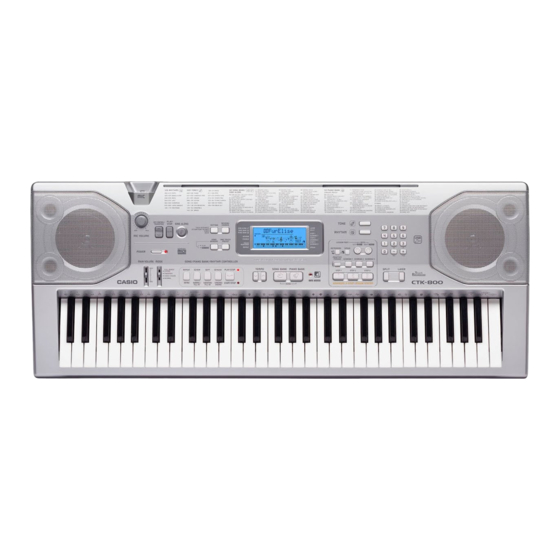
- Page 1 (without price) CTK-800 JUN. 2005 CTK-800 ELECTRONIC KEYBOARD Ver.1 : Dec. 2009 INDEX...
-
Page 2: Table Of Contents
CONTENTS Specifications ---------------------------------------------------------------------------------------------- 1 Block Diagram --------------------------------------------------------------------------------------------- 3 Circuit Description --------------------------------------------------------------------------------------- 4 Printed Circuit Board ------------------------------------------------------------------------------------ 5 Disassembly ------------------------------------------------------------------------------------------------ 7 Diagnostic Program ------------------------------------------------------------------------------------ 12 Exploded View ------------------------------------------------------------------------------------------- 15 Parts List --------------------------------------------------------------------------------------------------- 16 Schematic Diagrams ----------------------------------------------------------------------------------- 19... -
Page 3: Specifications
Auto Accompaniment Rhythm Patterns: Tempo: Variable (226 steps, = 30 to 255) Chords: 3 fingering methods (CASIO CHORD, FINGERED, FULL RANGE CHORD) Rhythm Controller: START/STOP, INTRO, NORMAL/NORMAL FILL-IN, VARIATION/ VARIATION FILL- IN, SYNCHRO/ENDING Accomp Volume: 0 to 127 (128 steps) One Touch Presets: Recalls settings for tone, tempo, layer, and split. - Page 4 Power Jack: 9V DC Power Supply: 2-way Batteries: 6 D-size batteries Battery Life: Approximately 9 hours continuous operation on manganese batteries AC Adaptor: AD-5 Auto Power Off: Turns power off approximately 6 minutes after last key operation. Enabled under batter power only, can be disabled manually.
-
Page 5: Block Diagram
BLOCK DIAGRAM Phones/ AC ADAPTOR SUB PCB DC 9V Output (M706-PSA1) Speakers Power AMP CONSOLE PCB Battery Filter LA4598-E (M06-CNA3) NJM2068DD Power Supply Mic Volume Q2 ~ Q4 Filter NJM2068DD (5.3V) (5.3V) (9.0V) (9.0V) Main CONSOLE PCB LCD Controller Volume (M706-CNA2) ST7066U Button... -
Page 6: Circuit Description
CIRCUIT DESCRIPTION KEY MATRIX C#21 D#21 F#21 C#22 D#22 F#22 G#21 A#21 C#31 D#31 G#22 A#22 C#32 D#32 F#31 G#31 A#31 F#32 G#32 A#32 C#41 D#41 F#41 C#42 D#42 F#42 G#41 A#41 C#51 D#51 G#42 A#42 C#52 D#52 F#51 G#51 A#51 F#52 G#52... -
Page 7: Printed Circuit Board
PRINTED CIRCUIT BOARD MAIN PCB M706-MDA1 Top View Main PCB M706-MDA1 Bottom View — 5 —... - Page 8 CONSOLE PCB M706-CNA1 SUB PCB M706-PSA1 CONSOLE PCB M706-CNA2 CONSOLE PCB M706-CNA3 CONSOLE PCB M706-CNA4 — 6 —...
-
Page 9: Disassembly
DISASSEMBLY 1. Remove the battery cover and then battery. 2. Remove 27 screws and then upper case. 3. Remove two lead wires by soldering. 4. Remove two connectors by soldering. 5. Make the keyboard unit and the main unit apart. Connector (CN4) Connector (CN3) black... - Page 10 To remove the main PCB (M706-MD1). 6. Remove three screws on the PCB (M706-MD1). 7. Remove four connectors by soldering. 8. Remove the PCB (M706-MD1). Connector (CN7) Connector (CN1) Connector (CN8) Connector (CN2) Precaution while assembling the main PCB (M706-MD1). Number of pins on the PCB and pins on the cable are different.
- Page 11 To remove the console PCB (M706-CNA1, CNA2, CNA3). 13. Remove the microphone and the volume knob. 14. Remove two screws on the PCB (M706-CNA2). 15. Remove three screws on the PCB (M706-CNA3). 16. Remove 30 screws and then the PCB (M706-CNA1). Caution while assembling: 6 screws fixing the LCD unit are different size from other screws.
- Page 12 To remove the key PCB (CSM618T-KY1M, KY2M) 19. Remove 13 screws and the bottom case. Note: Tighten the screw with the arrow mark in the figure first when reassembling. 20. Remove 19 screws and then the key PCB (CSM618T-KY1M, KY2M). 21.
- Page 13 22. Remove 21 screws and then the white keys. Note: Pay attention to the positions of the screw holes when reassembling. 23. Remove the black keys. — 11 —...
-
Page 14: Diagnostic Program
DIAGNOSTIC PROGRAM Initial Setting 1. Connect the AC adaptor. 2. Connect a Sustain pedal. 3. "MODE" switch: NORMAL 4. "Main" volume: MAX NOTE: If there is no Sustain pedal, Sustain pedal check can be skipped. How to start diagnostic program 1. - Page 15 Message on LCD 6. Version check 1 Press “3” button. 2 Press “3” button. 3 Press “3” button. 7. Sound check 1 Press the “4” button. * When standing in the center, the tester hears the minimum test sound in an equal volume from both right and left speakers.
- Page 16 . Console LED check 1 Press the “SPEAK” button. * Keyboard LED must light in the undermentioned order. 1) DATA ACCESS 2) PLAY/STOP 3) START/STOP 10. APO check 1 Press the “PRACTICE PHRASE” button. * Go out from TEST mode (Power off). * The LCD turns off.
-
Page 17: Exploded View
EXPLODED VIEW CNA2 CNA1 CNA3 CNA4 – 15 –... -
Page 18: Parts List
PARTS LIST CTK-800 Notes: This parts list does not include the cosmetic parts, which parts are marked with item No. "R-X" in the exploded view. Contact our spare parts department if you need these parts for refurbish. 1. Prices and specifications are subject to change without prior notice. - Page 19 P r i c e I t e m Parts Code Parts Name Specification Q T Y Remarks Code Main PCB 10203305 PCB ASSY/MAIN TK-RJM505831*001 10197809 IC TC7WH123FU(TE12L.F 10158804 IC R1154H033B-T1-FB 10158805 IC RH5RL33AA-T1-FA IC5,6,13,14 10116986 IC SN74AHCT1G08DCKR 10197555 IC TC7SZ14FU(TE85L.F) 10159723 IC RN5VD28AA-TR-FA...
- Page 20 P r i c e I t e m Parts Code Parts Name Specification Q T Y Remarks Code Keyboard PCBs 10053891 PCB ASSY/KY1M M140687*9 D501 - D564 23010101 DIODE 1S2473T-77-T 10053893 PCB ASSY/KY2M M140688*9 D565 - D622 23010101 DIODE 1S2473T-77-T Keyboard Unit 69222720 KEY SET/LT WHITE...
-
Page 21: Schematic Diagrams
SCHEMATIC DIAGRAMS MAIN PCB M706-MDA1 — 19 —... - Page 22 SUB PCB M706-PSA1 — 20 —...
- Page 23 CONSOLE PCBs M706-CNA1, CNA2, CNA3, CNA4 — 21 —...
- Page 24 Keyboard PCBs JCM618T-KY1M, KY2M — 22 —...
- Page 25 Ver.1 : Dec. 2009 • Correction of the EXPLODED VIEW (P15) CASIO COMPUTER CO.,LTD. Overseas Service Division 6-2, Hon-machi 1-Chome Shibuya-ku, Tokyo 151-8543, Japan...