
Related Manuals for Buffalo CE371-N

Summary of Contents for Buffalo CE371-N
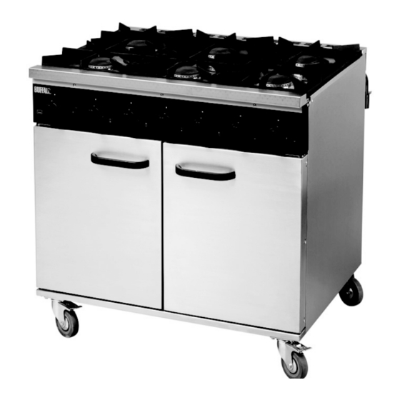
- Page 1 These instructions cover the 6 Burner Commercial Catering Ranges CE371-N & CE371-P Please read and keep these instructions : 00 44 (0)845 146 2887 www.nisbets.co.uk...
- Page 2 INTRODUCTION This appliance must be installed by a competent person in compliance with the installation and servicing instructions and national regulations in force at the time. Particular attention must be paid to the following: Gas Safety (Installation & Use) Regulations. Health and Safety at Work etc Act.
- Page 3 These appliances must be installed and serviced by a competent person as stipulated by the Gas Safety (Installation & Use) Regulations. IMPORTANT The installer must ensure that the installation of the appliance is in conformity with these instructions and National Regulations in force at the time of installation. Particular attention MUST be paid to: •...
-
Page 4: Gas Supply
INSTALLATION AND SERVICE GUIDE IT IS MOST IMPORTANT THAT THESE INSTRUCTIONS BE CONSULTED BEFORE INSTALLING AND COMMISSIONING THIS APPLIANCE. FAILURE TO COMPLY WITH THE SPECIFIED PROCEDURES MAY RESULT IN DAMAGE OR THE NEED FOR A SERVICE CALL. PREVENTATIVE MAINTENANCE CONTRACT In order to obtain maximum performance from this unit we would recommend that a Maintenance Contract be arranged. - Page 5 1.3 GAS PRESSURE ADJUSTMENT - NATURAL AND PROPANE GAS Country Appliance Category Inlet Pressure GB/IE Natural gas (G20) 20mbar GB/IE Propane (G31) 37mbar 1.4 HEAT INPUTS - NATURAL AND PROPANE GAS Heat Input Heat Input, Low Setting (kW net) (kW net) Country Gas Hotplate Oven...
-
Page 6: Instruction To User
rail behind the facia. 2. Now turn on main gas valve at supply to unit. 3. Ignite the oven burner on the unit as described in Section 2.3.3. As gas supply pipes may contain air, continue to repeat lighting procedure until flame is established. Turn the control knob to the maximum temperature position and ensure supply pressure is correct. - Page 7 3. Remove the two screws at each end of the fascia panel. 4. Lastly remove the 3 fixing screws from the front of the fascia panel. 5. Fascia panel can now be removed from the appliance. 3.1.2 Removal of the hotplate 1.
-
Page 8: Oven Thermostat
1. Undo thermocouple connection at FFD section of thermostat. 2. Undo FFD section cap at rear of thermostat and withdraw magnet unit. 3. Replace in reverse order, take care not to overtighten thermocouple. 3.3.4 Oven thermocouple 1. Remove hotplate as detailed in Section 3.1.2. 2. - Page 9 1. Check mains gas is ON. 2. Check pressure at pressure test point to ensure gas is flowing to the appliance. 3. If gas is present then check burner injector for blockage. 4. If injector is clear then check FFD magnet unit is engaging and allowing gas to pass. 5.
-
Page 10: Section 1 - About Your Appliance
USER’S GUIDE SECTION 1 - ABOUT YOUR APPLIANCE All models are fitted with flame failure devices to shut off gas supply to burners if flames are extinguished. The oven is thermostatically controlled. All taps are the safety type with fixed HIGH and LOW settings. Hotplate controls Control knob markings are as indicated below. -
Page 11: Section 3 - Cooking Hints
IMPORTANT INFORMATION PLEASE READ THE FOLLOWING VERY CAREFULLY..AVOID MIS-USE! (MIS-USE OF THIS PRODUCT CAN BE HARMFUL). Guidance Rules for the SAFE USE of a gastronome pan on the hotplate, Size 2/1 or 1/1 gastronome pans. • Whenever two or more hotplate burners are operated below a gastronome pan, the heat input of each burner should be reduced. -
Page 12: Section 4 - Cleaning And Maintenance
A 900mm wide oven will accommodate a 2/1 gastronorm tray. Single trays or dishes should be placed centrally. Trays must not be allowed to overhang the shelf in any direction as this will adversely affect heat circulation. In particular, NEVER block the space beyond the rear shelf upstand. - Page 13 the burner skirts. 5. Replace burner caps and skirts upon burner base and ensure the cap location fits within burner skirt notches. When burner head is properly located, it will not rotate. 6. Light burner to check that it operates correctly. Note: Ensure that all parts are dried thoroughly prior to relighting.
- Page 14 FAQ’s...
-
Page 15: Spares List
SPARES LIST Part Number Description 502989600 Bracket electrode support 082986600 Burner assembly 082982600 Burner cap assembly 082982500 Burner skirt 532991800 Oven door outer left hand side 532991900 Oven door outer right hand side 502991600 Door oven inner panel 082510900 Electrode oven 502992400 Facia panel 081502200... -
Page 16: Telephone Helpline
TELEPHONE HELPLINE: : 00 44 (0)845 146 2887 Fourth Way, Avonmouth, Bristol, UK, BS11 8TB www.nisbets.co.uk 082758402 © 07.2011...