Advertisement
The VCT-SP2BP is a camcorder support designed specially for use with Sony Digital HD Video Recorders. (Referred to below as "this unit")
Please read these operating instructions before use. After reading, keep them carefully for future reference.
* This unit may not be compatible with all video cameras in your country or region.

- Be very careful when opening and closing the shoulder pad, chest pad, casing S and casing C. There is a risk of catching your fingers.
- Do not hold this unit when the video camera is attached. The video camera may fall, leading to damage or injury.
Notes on Use (A)

- To adjust this unit, place the shoulder pad firmly against your shoulder and back and alter the angle until the viewfinder and LCD screen are easy to see. (Illustration A-a)
The weight load is not supported if the shoulder pad is in the air. - When carrying the video camera while attached to this unit, make sure this unit is folded up correctly without overlapping as shown in illustrations
![]() and
and ![]() . (Illustration A-b)
. (Illustration A-b) - When using this unit, hold the wide part of the chest pad flat against your chest so that the weight load is spread across your chest.
 and
and  . (Illustration A-b)
Main Features
- Supports the video camera during shooting by spreading the weight load across your shoulder, back and chest.
- Adjusting this unit keeps the video camera in the optimum viewpoint for shooting and reduces camera shake.
- The video camera can still be fitted to a tripod with this unit attached.
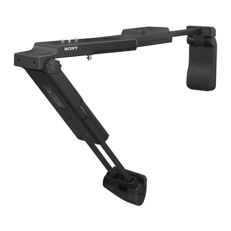
Names of Parts (B)

- Shoulder pad
- Arm S
- Locking lever S
- Casing S
- Pin
- Friction control dial
- Casing C
- RELEASE slider
- Locking lever C
- Arm C
- Chest pad
- Tripod screw hole
- Camera mounting screw
- Preset screw
Attaching the Video Camera (C)

- Place the video camera on its side so that you can see the bottom.
- Slide the RELEASE slider in the direction of the arrow to unlock this unit and open casing C.
- Align the pin of this unit with the pin hole of the video camera.
- Align the camera mounting screw of this unit with the tripod screw hole of the video camera and tighten it.
- The camera mounting screw of this unit is a coin screw. Tighten by hand and align the video camera before tightening with a coin.
Using this unit to shoot
Adjust the shooting position (D)

- Release locking lever S and pull out arm S.
- Open the shoulder pad and place it against the back of your shoulder.
- Fix the shooting position of the video camera and adjust arm S to the desired length.
Notes- Make sure arm S is placed firmly on your shoulder and the shoulder pad against your back.
- Check while actually looking at the viewfinder and LCD screen.
- You cannot adjust the position or height of this unit while it is attached to the video camera. With some video cameras, the height of the viewfinder may be difficult to align with your eye line.
- Tighten locking lever S.
- Release locking lever C and pull out arm C.
- Tilt the chest pad and place the wide part against the front of your body.
- Adjust the length of arm C and the angle of casing C so that the video camera is horizontal.
- Tighten locking lever C.
- Tighten the friction control dial by turning it clockwise so that casing C does not fall.
- If the weight is not properly supported, readjust the length and angle of arm S.
- If panning and tilting during shooting is difficult, loosen the friction control dial and move casing C forward.
Notes - The friction control dial adjusts the looseness when opening and closing casing S and casing C. Even if you tighten the friction control dial, you cannot completely fix the opening-closing angle of casing C.
Adjusting the preset position (E)

To maintain readiness for shooting, you can change the preset position (the maximum withdrawn position) of arm S according to the following steps.
- Loosen the preset screw on the rear of casing S.
- Adjust and hold arm S at the desired preset length.
- Slide the preset screw towards arm S.
- Slide the preset screw towards the friction control dial until it stops and then tighten it.
Notes- Place this unit on a flat surface to adjust it. It may be difficult to adjust the preset position properly if this unit is not level.
- You may be unable to set the preset position depending on the withdrawn length of arm S.
Attaching to a tripod and shooting (F)

- Fold up casing C, the shoulder pad and the chest pad.
- If the chest pad and shoulder pad overlap with the casing, the video camera can not sit level on the camera platform of the tripod.
- Align the pin hole of this unit with the pin of the tripod.
- For details, refer to the operation instructions of the tripod.
Attaching to the VCT-U14 (G)

Fitting the provided U14A and U14B adaptors lets you attach this unit to a VCT-U14 tripod adaptor.
Screw the U14A and U14B adaptors to the bottom of this unit as illustrated.
- When attaching to a tripod adaptor other than the VCT-U14, remove the U14A and U14B adaptors.
Fitting accessories to this unit (H)

Fitting the provided accessory plate lets you mount an HVR-DR60 hard disc recording unit or other accessory to this unit.
Screw the accessory plate to casing S as illustrated.
Storing
Remove this unit from the video camera, fold up the casings, arms and pads and store in the special pouch.
- You can also store this unit attached to the video camera in a soft carrying case (LCS-G1BP).
Notes
- Make sure the chest pad and shoulder pad are folded up as illustrated before storing. (Illustration A-b)
- If arm S and arm C are extended, shorten them before storing in the special pouch.
Specifications
Maximum dimensions: Approx. 359 × 52 × 134 mm (14.1 × 2 × 5.3 in.) (w/h/d)
Mass: Approx. 840 g (29.6 oz.)
Total weight of video camera and accessories to be mounted: Max. 4 kg (8.82 lb)
Included items: Camcorder Support (VCT-SP2BP) (1), Special pouch (1), Accessory plate (1), U14A adaptor (1), U14B adaptor (1), Screws (6), Set of printed documentation
Design and specifications are subject to change without notice.

Documents / Resources
References
Download manual
Here you can download full pdf version of manual, it may contain additional safety instructions, warranty information, FCC rules, etc.
Download Sony VCT-SP2BP - Camcorder Support Operating Instructions
Advertisement
Thank you! Your question has been received!

Need Assistance?
Do you have a question about the VCT-SP2BP that isn't answered in the manual? Leave your question here.