Motorola APX NEXT Installation Manual
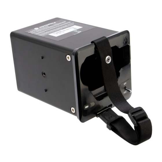
Vehicle charger
Hide thumbs
Also See for APX NEXT:
- User manual (58 pages) ,
- Quick start manual (29 pages) ,
- User manual (119 pages)
Advertisement
Quick Links
M
APX NEXT Vehicle Charger
PMPN4640 Installation Guide
*MN009444A01*
MN009444A01-AB
MOTOROLA, MOTO, MOTOROLA SOLUTIONS and the Stylized M
logo are trademarks or registered trademarks of Motorola Trademark
Holdings, LLC and are used under license. All other trademarks are the
property of their respective owners.
© 2022 Motorola Solutions, Inc. All rights reserved.
Printed in
blasting area, or in areas posted "Turn off two-way
radio." Obey all signs and instructions.
OPERATIONAL CAUTIONS
EFFICIENT SYSTEM OPERATION
•
All equipment must be properly grounded according to
Motorola Solutions installation instructions for safe
operation.
•
All equipment should be serviced only by an authorized
technician.
INSTALLING THE VEHICLE CHARGER
Mounting hardware supplied includes a trunnion bracket for
mounting the unit below the vehicle dashboard, on the floor,
or on the wall, and a cable for connection to the electrical
system of the vehicle. The bracket enables the charger to be
pivoted to a position that offers the best security to the
portable radio during rough driving conditions.
The vehicle charger is designed for 12 V or 24
V, negative ground system.
1.
Plan the location for mounting the charger. Identify the
routing paths for the cable and verify that the cable
length is adequate. Also check the mounting penetra-
tions required. On most vehicles, it is necessary to pen-
etrate the firewall to reach the battery. Check the
opposite side of the firewall for cable clearance before
drilling holes. Protect the cable where it passes through
the firewall by use of appropriate rubber grommets (not
supplied) or other protective measures.
Survey the firewall for existing holes occupied by vehicle wire
harnesses. Often there is an opportunity to route other cables
using the same path. Because of the wide variation in vehicle
design, these instructions may be modified to suit each
particular installation:
•
DO consider a mounting location which will allow the unit
to be mounted at a
•
45-degree up angle. This angle provides operational
convenience and physical security for the portable radio
under rough traveling conditions.
•
DO use heat shrink tubing on all splices.
•
DO ensure that the cable is not placed under stress, is
not exposed to weather, and is not subjected to damage
due to engine heat.
•
DO retain the in-line cable fuse when trimming the cable
to fit. Locate the in-line fuse as close as practical to the
supply voltage connection.
•
DO check the opposite sides of all mounting surfaces
before drilling, to insure that there are no obstructions,
such as vehicle wiring and fluid lines.
•
DO NOT attach the unit to any part of the vehicle that is
not rigid or is subject to excessive vibration.
•
DO NOT install the unit in an area where rain or snow can
easily get into it, such as next to a vehicle window which
may be left open.
•
DO NOT install the unit in a location where it could
interfere with the operator or operating controls of the
vehicle.
•
DO NOT dress the cable over sharp edges that could
cause wear or tearing of cable insulation.
SAFETY AND GENERAL INFORMATION
•All batteries can cause property damage
!
!
or bodily injury, or both, such as burns if a
conductive material such as jewelry, keys,
or beaded chains touches exposed
W A R N I N G
terminals. The material may complete an
electrical circuit (short circuit) and become quite hot.
Exercise care in handling any charged battery, particularly
when placing it inside a pocket, purse or other con tainer
with metal objects.
•
Do not replace or charge batteries in potentially explosive
atmosphere. Contact sparking can occur while installing
or removing batteries and cause an explosion.
•
Due to the risk of electrical shock or other physical injury,
never insert your hands into the charger pocket.
PRODUCT SAFETY AND RF EXPOSURE
COMPLIANCE
Before using this product, read the Product
Safety and RF Exposure booklet enclosed with
your radio which contains important operating
instructions for safe usage and RF energy
awareness and control for Compliance with
applicable Standards and Regulations.
•
DO NOT install the unit in a location where it may be
difficult for the operator to reach.
•
DO NOT install the unit where it may interfere with the
vehicle safety air bag deployment.
•
DO NOT install the unit where the LED indicators and
switch may become physically damaged.
2.
Using the trunnion bracket as a template, mark the
mounting surface drilling locations. It is recommended
that at least four screws be used, with 1/4 in. being the
preferred fastener diameter.
3.
Re-verify that there are no wires, fluid lines, or other
obstructions on the other side of the mounting location,
and drill appropriate sized holes for the mounting screws
to be used.
4.
Referring to Figure 1, mount the bracket using appropri-
ate screws, washers, lock washers, and nuts.
OPERATIONAL WARNINGS
VEHICLES WITH AN AIR BAG
•Do not place a portable radio or install
!
!
radio communications equipment in the
area over an air bag or in the air bag
deployment area. Air bags inflate with
W A R N I N G
great force. If a portable radio is placed
in the air bag deployment area and the air bag inflates,
the radio may be propelled with great force and cause
serious injury to occupants of the vehicle.
•
Installation of vehicle communication equipment should
be performed by a professional installer/technician
qualified in the requirements for such installations. The
size of an airbag, shape, and deployment area can vary
by vehicle make, model, and front compartment
configuration (for example, bench seat as opposed to
bucket seats).
•
Contact the corporate headquarters of the manufacturer
of the vehicle, if necessary, for specific airbag
information for the vehicle make, model, and front
compartment configuration involved in your
communication equipment installation.
BLASTING CAPS AND AREAS
•To avoid possible interference with
!
!
blasting operations, turn your radio off
and remove it from the charger when
you are near electrical blasting caps, in a
W A R N I N G
Figure 1 Installing the Vehicle Charger
5.
Insert the unit into the bracket, and install the washer
and threaded knob into the housing, as shown in Figure
1.
Advertisement

Related Manuals for Motorola APX NEXT


Summary of Contents for Motorola APX NEXT
- Page 1 • Due to the risk of electrical shock or other physical injury, logo are trademarks or registered trademarks of Motorola Trademark qualified in the requirements for such installations. The never insert your hands into the charger pocket.
- Page 2 Rotate the unit to the preplanned mounting angle and There are two methods for Step 8: tighten the two threaded knobs holding the charger to • Standard wiring to vehicle Switched A+: Charging the bracket. OFF with vehicle OFF. For installations where the Referring to Table 1 on page 2 and Figure 2, connect radio may be left in the charger with the ignition of the the red (A+) wire (with the inline fuse) of the supplied...