Advertisement
Quick Links
Advertisement

Related Manuals for GE GEP4.0-3-10


Summary of Contents for GE GEP4.0-3-10
- Page 1 4-20kW Three Phase Quick Installation Guide V1.1 SOLAR INVERTER www.gesolarinverter.com...
-
Page 2: Safety Disclaimer
Safety Precaution General Disclaimer • The information in this quick installation guide is subject to change due to product updates or other reasons. This guide cannot replace the product labels or the safety precautions in the user manual unless otherwise specified. All descriptions here are for guidance only. •... - Page 3 High voltage hazard. Power Potential risks exist. Wear off the inverter first before any proper PPE before any operations. operations. Read through the guide before Delayed discharge. Wait until any operations. the components are totally 5min discharged after power off. High temperature hazard.
- Page 4 Veiligheidsvoorschriften Algemene disclaimer • De informatie in deze beknopte installatiehandleiding kan worden gewijzigd als gevolg van productupdates of om andere redenen. Deze handleiding kan de productetiketten of de veiligheidsvoorschriften in de gebruiksaanwijzing niet vervangen, tenzij anders vermeld. Alle beschrijvingen zijn louter indicatief. •...
- Page 5 Controleer deze punten voordat u de stroom inschakelt Controlepunt De omvormer is stevig geïnstalleerd op een schone plaats die goed geventileerd en gemakkelijk te bereiken is. De PE-kabel, DC-ingangskabel, AC-uitgangskabel en communicatiekabel zijn correct en veilig aangesloten.
-
Page 6: Środki Ostrożności
Środki ostrożności Ogólne wyłączenie odpowiedzialności • Informacje zawarte w niniejszej instrukcji szybkiej instalacji mogą ulec zmianie ze względu na aktualizacje produktu lub z innych powodów. Niniejsza instrukcja nie może zastąpić etykiet produktu ani środków ostrożności w podręczniku użytkownika, chyba że stwierdzono inaczej. Wszystkie opisy mają... - Page 7 Ryzyko związane Istnieje potencjalne ryzyko. z wysokim napięciem. Przed Przed przystąpieniem do przystąpieniem do jakichkolwiek jakichkolwiek czynności czynności najpierw wyłączyć założyć odpowiednie ŚOI. zasilanie falownika. Przed przystąpieniem do Opóźnione rozładowanie. jakichkolwiek czynności Zaczekać, aż komponenty zapoznać się z instrukcją. zostaną całkowicie 5min rozładowane po wyłączeniu zasilania.
- Page 8 Precaução de segurança Aviso Geral • As informações desse guia de instalação rápida estão sujeitas a alterações por atualizações do produto ou outros motivos. O presente guia não substitui os rótulos do produto ou as precauções de segurança descritas no manual do usuário, salvo indicação em contrário. Todas as descrições presentes são exclusivamente para orientação.
- Page 9 Risco por alta tensão. Desligue Existem potenciais riscos. o inversor antes de efetuar Use o EPI adequado antes de qualquer operação. efetuar qualquer operação. Leia o guia na íntegra antes de Descarga com atraso. efetuar qualquer operação. Aguarde até os componentes estarem totalmente 5min descarregados após o...
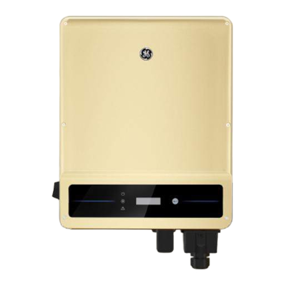
- Page 10 Product Introduction / Het product / Informacje ogólne o produkcie / Apresentação do produto GEP4.0-3-10, GEP5.0-3-10, GEP6.0- GEP12-3-10, GEP15-3-10, GEP20-3-10 3-10, GEP8.0-3-10, GEP8-3-AU10, GEP10-3-10, GEP10-3-AU10 11 12 175mm 415mm 198mm 110mm 120mm LED Indicator Button PE Terminal Mounting Plate DC Switch...
- Page 11 Inverter Installation / Installatie van de omvormer / Instalacja falownika / Instalação do inversor Packing List / Leveringsomvang / Zawartość opakowania / Lista de itens na embalagem x 1(optional) x 1(optional) N means the number of actual accessories may differ depending on different model.
- Page 12 Space Requirements / Benodigde ruimte / Wymagania dotyczące przestrzeni / Requisitos de espaço ≥ 300mm ≥ 200mm ≥ 200mm ≥ 300mm ≥ 500mm IP65 0%~100%RH Angle Requirements / Benodigde hoek / Wymagania dotyczące kątów / Requisitos de ângulo ≤...
- Page 13 Installing the Inverter / Omvormer monteren / Montaż falownika / Instalação do inversor Avoid the water pipes and cables buried in the wall when drilling holes.
- Page 14 NOTICE The PV box should be installed when GEP15-3-10 or GEP20-3-10 is used in Australia only. Install the cover of the PV box after connecting the DC input cable to the equipment. Otherwise, the DC input cable cannot be connected. 1.2~2N·m Electrical Connection / Elektrische aansluiting / Połączenia elektryczne / Conexão elétrica...
- Page 15 Connecting the DC Cable (with PV box) / DC-kabel aansluiten (met PV-doos) / Podłączanie przewodu DC (ze skrzynką PV) / Conectando o cabo CC (com caixa FV) Notice The PV box is designed for GEP 15-3-10 and GEP20-3-10 in Australia only. Install the cover of the PV box after connecting the DC input cable to the equipment.
- Page 16 Use a multimeter to measure the DC voltage and check the polarity of the connectors. Click Click Staubli MC4 DC Connector...
- Page 17 7~8mm 7~8mm ≤ ≤ Use a multimeter to measure the DC voltage and check the polarity of the connectors. Click Click...
- Page 18 Connecting the DC Cable (without PV box) / DC-kabel aansluiten (zonder PV-doos) / Podłączanie przewodu DC (bez skrzynki PV) / Conectando o cabo CC (sem caixa FV) Click Devalan DC Connector 7~8mm 7~8mm ≤ ≤ Use a multimeter to measure the DC voltage and check the polarity of the connectors.
- Page 19 Staubli MC4 DC Connector 7~8mm 7~8mm ≤ ≤ Use a multimeter to measure the DC voltage and check the polarity of the connectors. Click Click...
- Page 20 Connecting the AC Output Cable / AC-uitgangskabel aansluiten / Podłączanie przewodu wyjściowego AC / Conectando o cabo de saída CA L=L1+(1-2)mm 10-25mm ≤ ≤ L2 L3 1.2~2N·m 0.6~0.8N·m...
- Page 21 Connecting the Communication Cable (RS485, Meter, and DRED) / Communicatiekabel aansluiten (RS485, meter en DRED) / Podłączenie przewodu komunikacyjnego (RS485, miernika i DRED) / Conectando o cabo de comunicação (RS485, Medidor e DRED) RS485/ DRED Meter 6.5mm 25mm RS485/Meter (COM2) DRED (COM3) 1: RS485 B 1: DRM1/5...
- Page 22 Connecting the Remote Shutdown (RSD) Communication Cable / Communicatiekabel uitschakeling op afstand (RSD) aansluiten / Podłączanie przewodu komunikacyjnego zdalnego wyłączania (RSD) / Conectando o cabo de comunicação de desligamento remoto (RSD) RS485 6.5mm 25mm +: DRM4/8 -: REFGen 0.6~0.8N·m Installing Communication Module / Communicatiemodule installeren / Instalacja modułu komunikacyjnego / Instalando o módulo de comunicação NOTICE •...
- Page 23 COM1 Power On / Inschakelen / Włączenie zasilania / Ligando a alimentação Check the LED indicators Power ON Turn on Power OFF Turn off Commissioning / Inbedrijfstelling / Uruchomienie / Comissionamento Commissioning via LCD / Inbedrijfstelling via LCD / Uruchomienie przez LCD / Comissionamento via LCD 1.
- Page 24 Commissioning via SolarGo APP / Ingebruikneming via SolarGo-app / Uruchomienie przez aplikację SolarGo / Comissionamento via App SolarGo play SolarGo App Store <10m <5m SolarGo App Bluetooth: SOL-BLE******** WiFi: SOL-WiFi******** WiFi initial password: 12345678 Scan the QR Code on the equipment if you need to use GPRS.
- Page 25 Power Sight / Monitoramento via App Power Sight play Power Sight App Store Power Sight APP Test@ge.com Test Configure WiFi following the instructions. For WiFi module only. Please contact GE or the dealer to obtain the account and password.
- Page 26 For more detailed instructions, scan the QR code below to see the user manual. GEP 4-20kW Three Phase User Manual...
- Page 28 Global Sales & Service Network * GE is a registered trademark of General Electric Company and is used under license by GoodWe Technologies Co.,Ltd. © 2021 All Rights Reserved www.gesolarinverter.com sales@gesolarinverter.com; support@gesolarinverter.com 340-00545-01 Local Contacts...