Table of Contents
Advertisement
Quick Links
Advertisement
Table of Contents

Related Manuals for GE GEP3.5-1-10


Summary of Contents for GE GEP3.5-1-10
- Page 1 V1.0 Grid-Tied PV Inverter www.gesolarinverter.com...
- Page 2 Copyright Statement User Manual V1.0-2022-05-05 Trademarks and other GE trademarks are trademarks of General Electric Company. All other trademarks or registered trademarks mentioned in this manual are owned by General Electric Company. NOTICE The information in this user manual is subject to change due to product updates or other reasons.
-
Page 3: Table Of Contents
CONTENT User Manual V1.0-2022-05-05 CONTENT 1 About This Manual ..............1 1.1 Applicable Model ..................1 1.2 Target Audience ....................1 1.3 Symbol Definition ..................1 1.4 Updates ......................1 2 Safety Precaution ..............2 2.1 General Safety ....................2 2.2 DC Side: ......................2 2.3 AC Side ......................2 2.4 Inverter Installation ..................3 2.5 Personal Requirements ................3 2.6 EU Declaration of Conformity ..............4... - Page 4 CONTENT User Manual V1.0-2022-05-05 6 Electrical Connection ............15 6.1 Safety Precaution ..................15 6.2 Connecting the PE Cable ................16 6.3 Connecting the PV Input Cable ..............16 6.4 Connecting the AC Output Cable .............19 6.5 Communication ..................21 6.5.1 Communication Network Introduction ............21 6.5.1 Connecting the Communication Cable (optional) ...........21 6.5.3 Installing the Communication Module (optional) ...........26 7 Equipment Commissioning ..........27...
-
Page 5: About This Manual
This manual is subject to update without notice. For more product details and latest documents, visit https://www.gesolarinverter.com. 1.1 Applicable Model This manual applies to the listed inverters below (GEP or Inverter for short): Model Nominal Output Power Nominal Output Voltage GEP3.5-1-10 3.5kW GEP3.6-1-10 3.6kW GEP4.2-1-10 4.2kW 220/230V GEP4.6-1-10... -
Page 6: Safety Precaution
Safety Precaution User Manual V1.0-2022-05-05 2 Safety Precaution Notice The inverters are designed and tested strictly complies with related safety rules. Read and follow all the safety instructions and cautions before any operations. Improper operation might cause personal injury or property damage as the inverters are electrical equipment. 2.1 General Safety Notice •... -
Page 7: Inverter Installation
Safety Precaution User Manual V1.0-2022-05-05 2.4 Inverter Installation DANGER • Do not apply mechanical load to the terminals, otherwise the terminals can be damaged. • All labels and warning marks should be visible after the installation. Do not scrawl, damage, or cover any label on the device. •... -
Page 8: Eu Declaration Of Conformity
Safety Precaution User Manual V1.0-2022-05-05 2.6 EU Declaration of Conformity General Electric Company hereby declares that the inverter with wireless communication modules sold in the European market meets the requirements of the following directives: • Radio Equipment Directive 2014/53/EU (RED) •... -
Page 9: Product Introduction
User Manual V1.0-2022-05-05 Product Introduction 3 Product Introduction 3.1 Application Scenarios The GEP inverter is a single-phase PV string grid-tied inverter. The inverter converts the DC power generated by the PV module into AC power and feeds it into the utility grid. The intended use of the inverter is as follows: Circuit Utility... -
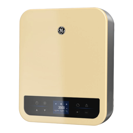
Page 10: Appearance
Product Introduction User Manual V1.0-2022-05-05 3.4 Appearance 3.4.1 Appearance Parts Description DC Switch Start or stop DC input. PV Input Terminal Used to connect the PV module DC input cables. Connect WiFi, LAN, WiFi/LAN communication Communication Module Port module. DRED/Remote Shutdown Used to connect the DRED or remote shutdown communication cable. -
Page 11: Indicators
User Manual V1.0-2022-05-05 Product Introduction Parts Description PE Terminal Used to connect the PE cable. Indicator Indicates working state of the inverter. Used to check the parameters of the inverter. Button Used to select menus displayed on the screen. Mounting Plate Used to install the inverter. -
Page 12: Nameplate
Product Introduction User Manual V1.0-2022-05-05 3.4.3 Nameplate The nameplate is for reference only. GE trademark, product type, and product model * * * * * Technical parameters Safety symbols and certification marks S/N: Contact information and serial number ********************************** Co.,Ltd. -
Page 13: Check And Storage
Check and Storage User Manual V1.0-2022-05-05 4 Check and Storage 4.1 Check Before Receiving Check the following items before receiving the product. 1. Check the outer packing box for damage, such as holes, cracks, deformation, and other signs of equipment damage. Do not unpack the package and contact the supplier as soon as possible if any damage is found. -
Page 14: Storage
Check and Storage User Manual V1.0-2022-05-05 4.3 Storage If the equipment is not to be installed or used immediately, please ensure that the storage environment meets the following requirements: 1. Do not unpack the outer package or throw the desiccant away. 2. -
Page 15: Installation
Installation User Manual V1.0-2022-05-05 5 Installation 5.1 Installation Requirements Installation Environment Requirements 1. Do not install the equipment in a place near flammable, explosive, or corrosive materials. 2. Install the equipment on a surface that is solid enough to bear the inverter weight. 3. - Page 16 Installation User Manual V1.0-2022-05-05 Mounting Support Requirements • The mounting support shall be nonflammable and fireproof. • Make sure that the support surface is solid enough to bear the product weight load. • Do not install the product on the support with poor sound insulation to avoid the noise generated by the working product, which may annoy the residents nearby.
- Page 17 Installation User Manual V1.0-2022-05-05 Installation Tool Requirements The following tools are recommended when installing the equipment. Use other auxiliary tools on site if necessary. DC terminal Goggles Safety shoes Dust mask Safety gloves crimping tool DC wiring Diagonal pliers Wire stripper Hammer drill Heat gun wrench...
-
Page 18: Inverter Installation
Installation User Manual V1.0-2022-05-05 5.2 Inverter Installation 5.2.1 Moving the Inverter CAUTION Move the inverter to the site before installation. Follow the instructions below to avoid personal injury or equipment damage. 1. Consider the weight of the equipment before moving it. Assign enough personnel to move the equipment to avoid personal injury. -
Page 19: Electrical Connection
Installation User Manual V1.0-2022-05-05 For Australia only. 6 Electrical Connection 6.1 Safety Precaution DANGER • Disconnect the DC switch and the AC output switch of the inverter to power off the inverter before any electrical connections. Do not work with power on. Otherwise, an electric shock may occur. -
Page 20: Connecting The Pe Cable
Electrical Connection User Manual V1.0-2022-05-05 6.2 Connecting the PE Cable WARNING • The PE cable connected to the enclosure of the inverter cannot replace the PE cable connected to the AC output port. Make sure that both of the two PE cables are securely connected. - Page 21 Electrical Connection User Manual V1.0-2022-05-05 Click NOTICE Seal the PV input terminals using waterproof covers when they are not to be used. Otherwise, the ingress protection rating will be influenced. Connecting the DC Input Cable Step 1 Prepare DC cables. Step 2 Crimp the crimp contacts.
- Page 22 Electrical Connection User Manual V1.0-2022-05-05 Click ≤600V Click MC4 PV connector ≤S≤6mm ≤600V Click Click...
-
Page 23: Connecting The Ac Output Cable
An AC circuit breaker shall be installed on the AC side to make sure that the inverter can safely disconnect the grid when an exception happens. Select the appropriate AC circuit breaker in compliance with local laws and regulations. Recommended AC circuit breakers: Inverter model AC circuit breaker GEP3.5-1-10 GEP3.6-1-10 GEP4.2-1-10 GEP4.6-1-10 GEP5.0-1-10 A type A RCD(Residual Current Device) shall be added to protect the equipment when the DC component of the leakage current exceeds limits. - Page 24 Electrical Connection User Manual V1.0-2022-05-05 Step 1 Make the AC output cable. Step 2 Disassemble the AC connector. Step 3 Insert the AC output cable into the AC connector. Step 4 Plut the AC connector into the inverter. Click Copper, NOTICE •...
-
Page 25: Communication
Electrical Connection User Manual V1.0-2022-05-05 6.5 Communication 6.5.1 Communication Network Introduction Power Limit Network The PV station generates power for self-consumption, but the electric equipment cannot consume all the generated power. The inverter can monitor the on-grid electric data in real-time and adjust the output power via a smart meter to avoid the residual current feeding back to the utility grid. - Page 26 Electrical Connection User Manual V1.0-2022-05-05 Communication Definition Function Type The port is reserved in compliance with grid 1(+): DRM4/8 Remote shutdown regulations in Europe. Related devices should be 2(-): REFGEN prepared by customers. Notice Make sure that the communication device is connected to the right terminal. Route the communication cable far away from any interference source or power cable to prevent the signal from being influenced.
- Page 27 Electrical Connection User Manual V1.0-2022-05-05 CT Communication Cable Function...
- Page 28 Electrical Connection User Manual V1.0-2022-05-05 DRED Communication Cable Function DRM1/5 DRM2/6 DRM3/7 DRM4/8 REFGEN COM/DRM0...
- Page 29 Electrical Connection User Manual V1.0-2022-05-05 Remote shutdown Communication Cable Function 1(+) DRM4/8 2(-) REFGEN 1(+): DRM4/8 2(-): REFGEN...
-
Page 30: Installing The Communication Module (Optional)
Electrical Connection User Manual V1.0-2022-05-05 6.5.3 Installing the Communication Module (optional) Plug a communication module into the inverter to establish a connection between the inverter and the smartphone or web pages. The communication module can be a Bluetooth module, WiFi module, LAN module, GPRS moduel, or 4G module. Set inverter parameters, check running information and fault information, and observe system status in time via the smartphone or web pages. -
Page 31: Equipment Commissioning
Equipment Commissioning User Manual V1.0-2022-05-05 7 Equipment Commissioning 7.1 Check Before Power ON Check Item The product is firmly installed at a clean place that is well-ventilated and easy to operate. The PE, DC input, AC output, and communication cables are connected correctly and securely. -
Page 32: System Commissioning
System Commissioning User Manual V1.0-2022-05-05 8 System Commissioning 8.1 Indicators and Buttons Indicator Status Description ON = EQUIPMENT POWER ON OFF = EQUIPMENT POWER OFF Power ON = THE INVERTER IS FEEDING POWER OFF = THE INVERTER IS NOT FEEDING POWER SINGLE SLOW FLASH = SELF CHECK BEFORE CONNECTING TO Operating THE GRID... - Page 33 System Commissioning User Manual V1.0-2022-05-05 Home Introduction Icon Description Communication Wi-Fi show the signal strength, RS485 shows the communication information icon address. Communication This icon indicates the current communication method including icon Wi-Fi and LAN and RS485. LVRT/HVRT icon The icon indicates that the system LVRT/HVRT function is on. The icon indicates the grid type selected including Delta Grid/Star Grid Type icon Grid.
- Page 34 System Commissioning User Manual V1.0-2022-05-05 Icon Description System time and date. E-Total icon Historical cumulative power generation. System status information. Carbon icon Energy conservation and emission reduction. Main Menu Level 1 menu interface through the up and down key cycle, in the historical information, configuration, advanced settings interface, press the Enter key will enter the Level 2 menu.
- Page 35 System Commissioning User Manual V1.0-2022-05-05 Main Menu Basic Settings is mainly used to set the commonly used parameters, including language settings, time settings, communication settings and safety setting. And these parameters can be set in the APP.
- Page 36 System Commissioning User Manual V1.0-2022-05-05 Advanced Settings Advanced settings are mainly used to set the function parameters of the equipment running. In order to prevent improper operation from customers, all advanced settings require a password to obtain advanced permission to operate advanced settings (Once password has bene entered, you can set the advanced settings menu for all items) .The default password is : 1111.In order to prevent customers from forgetting the password, all devices have a unique super password, bound to the serial number.
- Page 37 System Commissioning User Manual V1.0-2022-05-05...
- Page 38 System Commissioning User Manual V1.0-2022-05-05...
- Page 39 System Commissioning User Manual V1.0-2022-05-05 History Information The history information mainly includes the information of the generating capacity of the equipment, the power generation information mainly includes the amount of electricity generation, daily power generation, monthly power generation and annual power generation information.
-
Page 40: Inverter Parameter Introduction
System Commissioning User Manual V1.0-2022-05-05 8.2.2 Inverter Parameter Introduction Parameters Description Check the voltage of the utility grid. Check the AC output current of the inverter. Check the frequency of the utility grid. VPv1/2 Check the DC input voltage of the inverter. IPv1/2 Check the DC input current of the inverter. -
Page 41: Setting Inverter Parameters Via Solargo App
System Commissioning User Manual V1.0-2022-05-05 8.3 Setting Inverter Parameters via SolarGo App SolarGo app is a mobile application that communicates with the inverter via Bluetooth module, WIFi module or GPRS module. Commonly used functions are as follows: 1. Check the operating data, software version, alarms, etc. 2. -
Page 42: Maintenance
Maintenance User Manual V1.0-2022-05-05 9 Maintenance 9.1 Power Off the Inverter DANGER • Power off the inverter before operations and maintenance. Otherwise, the inverter may be damaged or electric shocks may occur. • Delayed discharge. Wait until the components are discharged after power off. Step 1 (optional) Send shutdown command to the inverter. - Page 43 Maintenance User Manual V1.0-2022-05-05 Solutions Type of fault 1. Disconnect DC switch, take off DC connector, check the impedance between PV (+) & PV(-) to earth. 2. If impedance is less than 100 kΩ, please check the insulation of PV string wiring to earth. 3.
- Page 44 Maintenance User Manual V1.0-2022-05-05 Solutions Type of fault Relay-Check Failure DCI Injection High EEPROM R/W Failure SCI Failure 1. Turn off DC switch of the inverter. SPI Failure 2. Wait till the inverter's LCD light is off. DC BUS High 3.
-
Page 45: Routine Maintenance
Maintenance User Manual V1.0-2022-05-05 9.5 Routine Maintenance Maintaining Item Maintaining Method Maintaining Period Check the heat sink, air intake, and air System Clean Once 6-12 months outlet for foreign matter or dust. Turn the DC switch on and off ten DC Switch consecutive times to make sure that it is Once a year... -
Page 46: Technical Parameters
Technical Parameters User Manual V1.0-2022-05-05 10 Technical Parameters Technical Data GEP3.5-1-10 GEP3.6-1-10 GEP4.2-1-10 Input Max.Input Power (W) 5500 5500 6300 Max.Input Voltage (V) MPPT Operating Voltage Range (V) 80~550 80~550 80~550 MPPT Voltage Range at Nominal Power 180~500 180~500 210~500... - Page 47 Technical Parameters User Manual V1.0-2022-05-05 Technical Data GEP3.5-1-10 GEP3.6-1-10 GEP4.2-1-10 Max. Efficiency 98.3% 98.3% 98.3% European Efficiency 97.5% 97.5% 97.6% Protection PV Insulation Resistance Detection Integrated Residual Current Monitoring Integrated PV Reverse Polarity Protection Integrated Anti-islanding Protection Integrated AC Overcurrent Protection...
- Page 48 Technical Parameters User Manual V1.0-2022-05-05 Technical Data GEP4.6-1-10 GEP5.0-1-10 Input Max.Input Power (W) 7500 7500 Max.Input Voltage (V) MPPT Operating Voltage Range (V) 80~550 80~550 MPPT Voltage Range at Nominal Power 210~500 240~500 Start-up Voltage (V) Nominal Input Voltage (V) Max.
- Page 49 Technical Parameters User Manual V1.0-2022-05-05 Technical Data GEP4.6-1-10 GEP5.0-1-10 Protection PV Insulation Resistance Detection Integrated Residual Current Monitoring Integrated PV Reverse Polarity Protection Integrated Anti-islanding Protection Integrated AC Overcurrent Protection Integrated AC Short Circuit Protection Integrated AC Overvoltage Protection Integrated DC Switch Integrated DC Surge Protection...
- Page 50 Global Sales & Service Network * GE is a registered trademark of General Electric Company and is used under license by GoodWe Technologies Co., Ltd. © 2022 All Rights Reserved No.90 Zijin Rd., New District, Suzhou, 215011, China www.gesolarinverter.com sales@gesolarinverter.com; support@gesolarinveter.com...