Table of Contents
Advertisement
Quick Links
Advertisement
Table of Contents
Troubleshooting

Related Manuals for Mitsubishi MELSEC AJ65BT-R2


Summary of Contents for Mitsubishi MELSEC AJ65BT-R2
-
Page 3: Safety Instructions
SAFETY INSTRUCTIONS (Always read these instructions before using this equipment.) Before using this product, please read this manual and the relevant manuals introduced in this manual carefully and pay full attention to safety to handle the product correctly. The instructions given in this manual are concerned with this product. For the safety instructions of the programmable controller system, please read the CPU module user's manual. - Page 4 CAUTION Do not bind the control wire or communication cable with the main circuit or power wire, or place the control wire near these. Separate by at least 100mm or more. Failure to observe this could lead to malfunctions caused by noise. Always connect the master module and CC-Link dedicated cable at the data link terminal block.
- Page 5 [Wiring Instructions] CAUTION Before starting installation or wiring work, be sure to shut off all phases of external power supply used by the system. Failure to shut off all phases could lead to electric shocks, product damage or malfunctioning. Always install the terminal covers enclosed with the product before turning ON the power or operating the product after installation or wiring work.
- Page 6 [Startup/Maintenance Instructions] CAUTION When power is ON, do not touch the terminals. Doing so can cause an electric shock or malfunction. Before cleaning or tightening the terminal screws and module mounting screws, be sure to shut off all phases of external power supply used by the system. Failure to shut off all phases could lead to module trouble or malfunctioning.
-
Page 7: Revisions
This manual does not guarantee the implementation of industrial rights or other rights, and does not authorize the implementation rights. Mitsubishi shall not be held liable for any problems regarding industrial rights that occur through the use of the contents given in this manual. -
Page 8: Table Of Contents
INTRODUCTION Thank you for purchasing the Mitsubishi general-purpose programmable controller MELSEC-A. Always read through this manual, and fully comprehend the functions and performance of the A Series programmable controller before starting use to ensure correct usage of this product. Make sure that this manual is delivered to the final user. - Page 9 4.5.1 Precautions for handling the CC-Link dedicated cables..............4- 8 4.5.2 Connection of the CC-Link dedicated cables ................... 4- 8 4.5.3 Connection with external device ....................... 4- 9 4.6 Checking the module’s state (Hardware test) ..................4- 11 5. PRELIMINARY INFORMATION 5- 1 to 5- 46 5.1 System used in this manual........................
- Page 10 7.4.4 Precautions............................7- 21 7.5 Registration frames..........................7- 22 7.5.1 List of default registration frames..................... 7- 23 7.5.2 Details of user registration frames....................7- 25 8. OTHER FUNCTIONS 8- 1 to 8- 24 8.1 Canceling data communication to an external device ................8- 1 8.2 Forcibly completing reception ........................
-
Page 11: About Manuals
(Sold separately) Compliance with the EMC/Low Voltage Directive When incorporating the Mitsubishi programmable controller into other machinery or equipment and keeping compliance with the EMC and low voltage directives, refer to Chapter 3, "EMC Directives and Low Voltage Directives" of the User's Manual (Hardware) included with the CPU module or base unit used. -
Page 12: Using This Manual
Using This Manual This section "Using this manual" describes the R2 usage in categories of purpose. Refer to the following details when using this manual. (1) To find the characteristics of R2 (Section 1.1) The features are described in section 1.1. (2) To find the system configuration (Section 2.1) The configuration of a system using R2 is explained in section 2.1. -
Page 13: Generic Terms And Abbreviations
Generic Terms and Abbreviations Unless specially noted, the following generic terms and abbreviations are used in this manual to explain the AJ65BT-R2 type RS-232-C interface module. Generic term/abbreviation Details of generic term/abbreviation Abbreviation for AJ65BT-R2 type RS-232-C interface module. CC-Link Abbreviation for Control &... -
Page 14: Definitions And Details Of Terms
Definitions and Details of Terms The definitions and details of terms used in this manual are explained below. This indicates the buffer memory address of the master station. This indicates the buffer memory address of R2. (3) Master station The station that controls the remote station, local station and intelligent device station. - Page 15 1 OUTLINE MELSEC-A 1. OUTLINE This User's Manual explains the features and specifications of the R2 used as the intelligent device station of the CC-Link, communication with an external device, and the special specifications, etc. R2 can exchange data with an external device, such as an RS-232-C connection type barcode reader, ID controller or general-purpose personal computer.
-
Page 16: Outline
1 OUTLINE MELSEC-A 1.1 Features (1) Easy communication by using the buffer memory automatic update function. This function automatically updates the buffer memory between the R2 and master station at the timing set in R2. With this, a program to read and write between the R2 and master station can be eliminated. - Page 17 1 OUTLINE MELSEC-A (2) Addition of frame during data transmission/reception with external device By adding a frame to the head and end, a statement format matching the specifications of the external device, such as the barcode reader or ID controller, can be created and communicated.
- Page 18 1 OUTLINE MELSEC-A MEMO 1 - 4...
-
Page 19: System Configuration
2 SYSTEM CONFIGURATION MELSEC-A 2. SYSTEM CONFIGURATION The system configuration for using R2 is shown explained in this section. 2.1 System configuration The system configuration for using R2 is shown below. Up to 26 R2 modules can be connected to one master station. CC-Link master/local station (master station) CC-Link master/local station (local station) CC-Link dedicated cable... -
Page 20: Applicable Systems
2 SYSTEM CONFIGURATION MELSEC-A 2.2 Applicable systems The master module of the CC-Link system that can use R2, and the programmable controller CPU that can use the CC-Link dedicated commands are explained in this section. (1) Applicable master modules The following indicates the master modules that can use the R2. AJ61BT11 A1SJ61BT11 AJ61QBT11... -
Page 21: Specifications
*3 Do not use or store the programmable controller in the environment where the pressure is higher than the atmospheric pressure at sea level. Otherwise, malfunction may result. To use the programmable controller in high-pressure environment, contact your nearest Mitsubishi representative. 3 - 1... -
Page 22: Performance Specifications
3 SPECIFICATIONS MELSEC-A 3.2 Performance specifications The R2 performance specifications are shown below. (1) RS-232-C specifications Item Specifications Interface specifications RS-232-C compliant, 1 channel (Refer to section 3.3) Transmission method Full duplex communication method Synchronization method Start-stop synchronization method Transmission speed 300, 600, 1200, 2400, 4800, 9600, 19200bps (Select with RS-232-C transmission specification setting switch) Data format... -
Page 23: Rs-232-C Interface Specifications
3 SPECIFICATIONS MELSEC-A 3.3 RS-232-C interface specifications The specifications of the RS-232-C interface for connection with an external device are shown below. Signal direction Signal Name external abbrev. device Reception carrier The following type of connector detection is mounted on the R2 side, so Reception data RD(RXD) use a mate connector that... -
Page 24: General-Purpose Input/Output Specifications
3 SPECIFICATIONS MELSEC-A 3.4 General-purpose input/output specifications The general-purpose input/output specifications of the R2 are shown below. (1) General-purpose input specifications DC input (Positive common/negative common shared type) External connection view No. of input points 2 points Insulation method Photo coupler insulation Rated input voltage 24VDC Rated input current... - Page 25 3 SPECIFICATIONS MELSEC-A (2) General-purpose output specifications Transistor output (sink type) External connection view No. of output points 2 points Insulation method Photo coupler insulation Rated load voltage 12/24VDC Working load voltage 10.2 to 28.8VDC (ripple rate within 5%) range 5 YC Max.
-
Page 26: List Of Functions
3 SPECIFICATIONS MELSEC-A 3.5 List of functions The R2 functions are shown below. Relation with main function Function Explanation Reference Trans- Recep- mission tion Non-procedural Non-procedural data transmission/reception with external Main communication device such as barcode reader, ID controller, general- –... -
Page 27: Input/Output Signals For Master Module
3 SPECIFICATIONS MELSEC-A 3.6 Input/output signals for master module The input/output signals (RX/RY) for the R2 master module are explained in this section. 3.6.1 List of input/output signals A list of the R2 input/output signals is shown below. Signal direction Master module Signal direction Master module Device No. -
Page 28: Details Of Input/Output Signals
3 SPECIFICATIONS MELSEC-A 3.6.2 Details of input/output signals A detailed explanation of the R2 input/output signals is given below. The lines in the timing chart indicate the following details. (1) Remote input (RX) Device No. Signal name Details When transmitting data to an external device connected to R2, after the transmission data is written into the R2 transmission area, the transmission request (RYn0) is turned ON. - Page 29 3 SPECIFICATIONS MELSEC-A Device No. Signal name Details The OS reception area clear request (RYn6) is turned ON to abort the data in the R2 OS reception area. When OS reception area clear is completed, the R2 turns the OS reception area clear complete (RXn6) ON, so the OS reception area clear request (RYn6) will turn OFF.
- Page 30 3 SPECIFICATIONS MELSEC-A Device No. Signal name Details This signal indicates the R2 error state. If the R2 ERR.LED is lit, the error status (RX(n+1)A) turns ON, and when the ERR.LED is OFF, the status turns OFF. When an error occurs, the R2 stores the error code in the error code storage area to 1B2 When the error reset request (RY(n+1)A) is turned ON after remedying the error cause, the error status (RX(n+1)A) can be turned OFF.
- Page 31 3 SPECIFICATIONS MELSEC-A (2) Remote output (RY) Device No. Signal name Details RYn0 Transmission request Refer to the sections on RXn0 and RXn1. To cancel the transmission after requesting transmission from R2, the transmission will be canceled when the transmission cancel request (RYn1) turns ON. When the transmission is forcibly canceled, the transmission normal complete (RXn0) or transmission error complete (RXn1) will turn ON.
- Page 32 3 SPECIFICATIONS MELSEC-A Device No. Signal name Details This signal turns the RS (RTS) signal of the RS-232-C line ON or OFF. Note that when "RS (RTS) signal status designation ( )" is set to "Always ON RS(RTS) (0)", the signal will remain ON even if the RS signal setting (RYn9) is turned ON or RYn9 signal * OFF.
-
Page 33: R2 Buffer Memory List
3 SPECIFICATIONS MELSEC-A 3.7 R2 buffer memory list The entire configuration of the R2 buffer memory is explained in this section. The contents of the R2 buffer memory are cleared to the default values when the power is turned OFF. However, if the user has registered the default values in the R2 EEPROM, the EEPROM default values will be written in when the power is turned ON. - Page 34 3 SPECIFICATIONS MELSEC-A (1) Area for designating various assignments Address Default Initializa- EEPROM Name Update Reference (hexadecimal) value tion registration Transmission area head address designation Section Transmission area size designation Head address M station Required Possible designation area Reception area head address designation Section Reception area size...
- Page 35 3 SPECIFICATIONS MELSEC-A Address Default Initializa- EEPROM Name Update Reference (hexadecimal) value tion registration Transmission size R2 side head address User registration (Fixed value: 4004 4004 frame area Master station side offset address Transmission size R2 side head address Automatic Monitor Section update area...
- Page 36 3 SPECIFICATIONS MELSEC-A (2) Parameter area Address Default Initializa- EEPROM Name Update Reference (hexadecimal) value tion registration Section Flow control designation Section RS (RTS) signal status designation Section Word/byte unit designation M station Required Possible 6.1, 6.2 Section ASCII-BIN conversion designation Section Transient timeout time designation 5.6.1...
- Page 37 3 SPECIFICATIONS MELSEC-A (3) Setting status storage area Address Default Initializa- EEPROM Name Update Reference (hexadecimal) value tion registration Station No. setting switch Data link transmission speed setting switch Mode setting switch Section RS-232-C transmission speed 8.10 RS-232-C data bit length required possible RS-232-C parity bit presence...
- Page 38 3 SPECIFICATIONS MELSEC-A (5) EEPROM area Address Default Initializa- EEPROM Name Update Reference (hexadecimal) value tion registration Section 8.8 and EEPROM function designation Section M station 7.5.2 required possible Section User-registered frame No. designation 7.5.2 System area (Use prohibited) – –...
-
Page 39: Transmission Delay Time
3 SPECIFICATIONS MELSEC-A 3.8 Transmission delay time The transmission delay time (time for data to be conveyed) is shown below. (1) Calculation expressions Calculation expression (unit: ms) When the master Details When the master station is the A/QnA station is the Q Series Series ×... -
Page 40: Transmission/Reception Time
3 SPECIFICATIONS MELSEC-A 3.9 Transmission/reception time The transmission/reception time is shown below. 3.9.1 When using buffer memory automatic update function The transmission time is the time from when the transmission request (RYn0) turns ON to when the R2 turns the transmission normal complete (RXn0) ON. The reception time is the time from when the R2 starts receiving the data to when the reception normal read request (RXn2) and reception error read request (RXn3) are turned ON by the R2. - Page 41 3 SPECIFICATIONS MELSEC-A (2) Calculation example (a) Transmission time An example of calculating the transmission time for transmitting 10 words (20 bytes) of data is shown below. Item Setting details Transmission size of each area Default value Transmission speed 156kbps No.
- Page 42 3 SPECIFICATIONS MELSEC-A (b) Reception time An example for calculating the reception time when receiving 10 words (20 bytes) of data is shown below. Item Setting details Transmission size of each area Default value Transmission speed 156kbps No. of connected modules Only one R2 module Master station sequence program scan time 20ms (Hypothetical)
-
Page 43: When Using Transmission/Reception Buffer
3 SPECIFICATIONS MELSEC-A 3.9.2 When using transmission/reception buffer The transmission time is the time from when the transmission data is stored in the R2, the transmission request (RYn0) is turned ON to when the transmission normal complete (RXn0) is turned ON by the R2. The reception time is the time from when the R2 starts receiving the data, the reception normal read request (RXn2) and reception error read request (RXn3) are turned ON by the R2, to when the data is received. - Page 44 3 SPECIFICATIONS MELSEC-A (2) Calculation example (a) Transmission time An example of calculating the transmission time for transmitting 10 words (20 bytes) of data is shown below. Item Setting details Transmission speed 156kbps No. of connected modules Only one R2 module Master station sequence program scan time 20ms (Hypothetical) Transmission speed...
- Page 45 3 SPECIFICATIONS MELSEC-A (b) Reception time An example for calculating the reception time when receiving 10 words (20 bytes) of data is shown below. Item Setting details Transmission speed 156kbps No. of connected modules Only one R2 module Master station sequence program scan time 20ms (Hypothetical) Transmission speed 9600bps...
- Page 46 3 SPECIFICATIONS MELSEC-A MEMO 3 - 26...
-
Page 47: Procedures And Settings Before Operatiion
4 PROCEDURES AND SETTINGS BEFORE OPERATION MELSEC-A 4. PROCEDURES AND SETTINGS BEFORE OPERATION The operation procedures before starting the R2 operation, names and settings of each R2 section, wiring method and hardware test are described in this section. 4.1 Procedures before operation The procedures before operating the R2 are explained below. - Page 48 4 PROCEDURES AND SETTINGS BEFORE OPERATION MELSEC-A (Continued from previous page) Create a program. 1. Initializing the master module (Refer to Section 5.4.) 2. Reading the remote input (RX) (Refer to Section 5.3 (2).) 3. Confirming the R2 data link state (Refer to Section 5.3 (3).) 4.
-
Page 49: Precautions For Handling
4 PROCEDURES AND SETTINGS BEFORE OPERATION MELSEC-A 4.2 Precautions for handling The precautions for handling the R2 are shown below. • Do not touch the terminals or connectors while the power is ON. DANGER Failure to observe this could lead to electric shocks or malfunctioning. •... - Page 50 4 PROCEDURES AND SETTINGS BEFORE OPERATION MELSEC-A (1) Tighten the module installation screws and terminal block screws within the following range. Screw place Tightening torque range Remarks ⋅ Module installation screw (M4 screw) 0.78 to 1.18N ⋅ Terminal block terminal screw (M3.5 screw) 0.59 to 0.88N ⋅...
-
Page 51: Installation Environment
4 PROCEDURES AND SETTINGS BEFORE OPERATION MELSEC-A 4.3 Installation environment When installing the programmable controller, refer to the CC-Link system master module's User's Manual. 4 - 5... -
Page 52: Names Of Each Part, And Settings
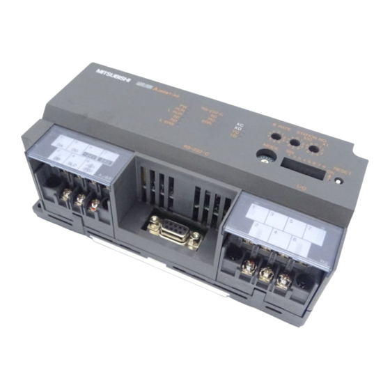
4 PROCEDURES AND SETTINGS BEFORE OPERATION MELSEC-A 4.4 Names of each part, and settings The names of the parts in the R2, the LED details, and the settings for each switch are explained in this section. (10) Name Details (1) Operation display LEDs LED name Details ON: Power is ON. - Page 53 4 PROCEDURES AND SETTINGS BEFORE OPERATION MELSEC-A Name Details (2) Station No. setting switch Set the module's station No. (Default setting: 0) Setting range: 1 to 64 (0: Master module) " 10" sets the 10th place of the station No.. "...
-
Page 54: Wiring
4 PROCEDURES AND SETTINGS BEFORE OPERATION MELSEC-A 4.5 Wiring 4.5.1 Precautions for handling the CC-Link dedicated cables Avoid the following extreme handling. Such handling will damage the CC-Link dedicated cables. • Compress the cable with a sharp edge. • Twist the cable extremely. •... -
Page 55: Connection With External Device
4 PROCEDURES AND SETTINGS BEFORE OPERATION MELSEC-A The method of connecting the R2, master module and remote module with a CC-Link dedicated cable is shown below. Master module Remote module Terminator Terminator CC-Link dedicated CC-Link dedicated cable cable POINT Always connect the modules on both ends of the data link with the "terminator" enclosed with the master module. - Page 56 4 PROCEDURES AND SETTINGS BEFORE OPERATION MELSEC-A (3) Precautions for connections R2 does not use the CD signal as a control signal in sending/receiving data to/from an external device. Handle the connection cable's FG signal and shield as described below. Connection method Remarks FG signal Connect to the body of the...
-
Page 57: Checking The Module's State (Hardware Test)
4 PROCEDURES AND SETTINGS BEFORE OPERATION MELSEC-A 4.6 Checking the module's state (Hardware test) Confirm that the R2 operates normally as a single module. Always carry out this test before structuring the system. Execute the test with the following procedure. Start Disconnect the CC-Link dedicated cable for the data link from R2. - Page 58 Details Measures ROM check error The hardware may be faulty, so contact your nearest dealer or Mitsubishi branch. RAM check error Disconnect the CC-Link dedicated cable. If the ERR.LED does not flicker even when the Hardware error, or CC-Link dedicated CC-Link dedicated cable is disconnected, the cable is still connected.
-
Page 59: Preliminary Information
5 PRELIMINARY INFORMATION MELSEC-A 5. PRELIMINARY INFORMATION 5.1 System used in this manual An example of the sequence program explained in this manual is described for the following system. Refer to the CC-Link Master Module User's Manual (Details) for details on the sequence program for the entire CC-Link system. - Page 60 5 PRELIMINARY INFORMATION MELSEC-A (3) Master station buffer memory settings (buffer memory size) Automatic update Transmission buffer Reception buffer buffer When using the buffer memory automatic update function When using the transmission/reception buffer (4) R2 buffer memory setting The R2 buffer memory is used with the factory-set state (default values). 5 - 2...
-
Page 61: Programming Precautions
5 PRELIMINARY INFORMATION MELSEC-A 5.2 Programming Precautions 5.2.1 About bank changing of the A series master module When using the R2, the master station's automatic update buffer or transmission/reception buffer is used. With the A Series master module (AJ61BT11/A1SJ61BT11), the automatic update buffer and transmission/reception buffer are divided with banks. - Page 62 5 PRELIMINARY INFORMATION MELSEC-A (2) Program Create the program for changing the bank as shown below. Refer to section 5.1 for details on the program conditions. (a) Program for changing to bank 0 Changeover execution Specify partial refresh Specify bank 0 Execute partial refresh (b) Program for changing to bank 1...
-
Page 63: About Dedicated Commands For Use Of The Buffer Memory Automatic Update Function
5 PRELIMINARY INFORMATION MELSEC-A 5.2.2 About dedicated commands for use of the buffer memory automatic update function When the buffer memory automatic update function is used, the R2 buffer memory to be specified differs as described below between when the FROM/TO command is used and when the dedicated command is used. -
Page 64: Program Basic Format
5 PRELIMINARY INFORMATION MELSEC-A 5.3 Program basic format The basic format for creating a program is shown below. The program is created with the following arrangement. Refer to section 5.1 for details on the program conditions. (1) Master station initialization (Refer to section 5.4.) (Parameter settings, start of data link) (2) Reading of remote input (RX) (3) Confirmation of R2 data link state... - Page 65 5 PRELIMINARY INFORMATION MELSEC-A Create a program that detects the R2 data link state and establishes an interlock. Read R2 data link state R2 data link normal Program for R2 error R2 data link error Create a program that initializes the R2. (Refer to section 5.5) Create a program that transmits data to the external device.
- Page 66 5 PRELIMINARY INFORMATION MELSEC-A (8) Create the following program and write Y100 to Y11F into RYn0 to RY(n+1)F. Module error (master station) Module ready (master station) Local station data link state (master station) Changeover to bank 0 Write 'Y100 to Y11F' to 'RYn0 to RY(n+1)F' POINT When using QCPU (Q mode) or QnACPU, setting automatic refresh parameters...
-
Page 67: Initializing The Master Station
5 PRELIMINARY INFORMATION MELSEC-A 5.4 Initializing the master station Create the following program to initialize (set the parameters, start the data link) the master station. Refer to section 5.1 for details on the program conditions. (Example) No. of connected modules: One module, Connected station: R2 (Station No. - Page 68 5 PRELIMINARY INFORMATION MELSEC-A (2) Station information ( (1st module) to (64th module)) M 20 M 5F Set the type of remote I/O station, remote device station, intelligent device station and local station connected to the master station. This must be set for each module connected. (bit) N o .
- Page 69 5 PRELIMINARY INFORMATION MELSEC-A (b) Automatic update buffer Set this when communicating with R2 using the buffer memory automatic update function. When using the R2 automatic update area with the default value, "600 " is required. Even if the automatic update area size is set to the minimum, the default setting area amount (1A0 ) + the status storage area amount (20 ) must be...
-
Page 70: Initializing The R2
5 PRELIMINARY INFORMATION MELSEC-A 5.5 Initializing the R2 The methods for initializing the R2 are described below. 5.5.1 Using the buffer memory automatic update function Initialization when using the buffer memory automatic update function changes the contents of R 2 0 to 19F The values of the initialization area ( R 2 0 to 19F... - Page 71 5 PRELIMINARY INFORMATION MELSEC-A (3) Timing chart Initial data read request signal (RY(n+1)9) Initial data read complete signal (RX(n+1)9) Remote station READY (RX(n+1)B) Initialization request signal (RYn4) Initialization normal/error complete signal (RXn4/RXn5) Master station automatic update buffer R2 initialization area Carried out with sequence program Carried out by R2 Details...
- Page 72 5 PRELIMINARY INFORMATION MELSEC-A (4) Program Refer to section 5.1 for details on the program conditions. Master station initialization (parameter setting, data link setting) (Refer to section 5.4.) Reading of remote input (RX) (Refer to section 5.3 (2).) Confirmation of R2 data link status (Refer to section 5.3 (3).) Set initial data read request R2 normal...
-
Page 73: Using The Transmission/Reception Buffer
5 PRELIMINARY INFORMATION MELSEC-A 5.5.2 Using the transmission/reception buffer Initialization using the transmission/reception buffer changes the contents of the R2 buffer memory using the transmission/reception buffer. By using this operation, the transmission/reception area address and size, the range of the buffer memory to be automatically updated, and the parameters, etc., can be changed from the default values. - Page 74 5 PRELIMINARY INFORMATION MELSEC-A (3) Timing chart Remote station read signal (RX(n+1)B) Intelligent device station access request signal (RY(n+1)E) Intelligent device station access complete signal (RX(n+1)E) Initialization request signal (RYn4) Initialization normal/error complete signal (RXn4/RXn5) Programmable controller CPU word device Master station transmission buffer Master station...
- Page 75 5 PRELIMINARY INFORMATION MELSEC-A (4) Program Refer to section 5.7.4 for details on writing the data using the transmission/reception buffer. Refer to section 5.1 for details on the program conditions. Master station initialization (parameter setting, data link setting) (Refer to section 5.4.) Reading of remote input (RX) (Refer to section 5.3 (2).) Confirmation of R2 data link status (Refer to section 5.3 (3).) Write initialization data to R2 (Refer to section 5.7.4.)
-
Page 76: Reading And Writing The Buffer Memory (Using The Buffer Memory Automatic Update Function)
5 PRELIMINARY INFORMATION MELSEC-A 5.6 Reading and writing the buffer memory (using the buffer memory automatic update function) The methods for reading and writing the R2 buffer memory using the buffer memory automatic update function is described in this section. When the buffer memory automatic update function is used, data can be read and written using the FROM/TO command, so the sequence program can be simplified. -
Page 77: Understanding The Roles Of Each Area
5 PRELIMINARY INFORMATION MELSEC-A 5.6.2 Understanding the roles of each area When using the buffer memory automatic update function, the information of each area in the automatic update area designation ( R 2 10 to 33 ) is important. The timing for carrying out automatic update in each area is determined by the R2. The application of each area differs according to the timing. - Page 78 5 PRELIMINARY INFORMATION MELSEC-A (b) Transmission area ( R 2 14 to 17 R 2 18 to 1B This area is used to store the data transmitted to the external device from the master station to the R2. When using a reading dedicated device, such as a barcode reader, the data does not need to be transmitted, so the transmission size ( R 2 14 R 2 18 ) can be set to "0".
- Page 79 5 PRELIMINARY INFORMATION MELSEC-A (d) Initialization area ( R 2 20 to 23 This area is used to store the initialization parameters in the master station, or to read them from the master station. This area is required during initialization, so use the default values. 1) Update timing The data is updated at the following timing.
- Page 80 5 PRELIMINARY INFORMATION MELSEC-A (e) EEPROM function area ( R 2 24 to 27 This area is used to initialize the EEPROM, and to register, call and delete the user registration frames. When the EEPROM is not to be initialized, or when the user registration frames are not to be registered, called or deleted, the transmission size ( R 2 24 ) can be set to "0".
- Page 81 5 PRELIMINARY INFORMATION MELSEC-A (g) Monitor transmission area ( R 2 2C to 2F R 2 30 to 33 This area is used to store the data transmitted from the external device using the monitor transmission function, from the master station to R2. When not using the monitor transmission function, the transmission size ( R 2 2C , R 2 30...
- Page 82 5 PRELIMINARY INFORMATION MELSEC-A (2) Buffer memory for setting each area The buffer memories used to set each area's information (transmission size, head address, master side head offset address) are shown below. Area name Transmission R2 side head Master station side Fixed value size address...
- Page 83 5 PRELIMINARY INFORMATION MELSEC-A (3) Default size of each area When totaled the default size of each area is 600 The size of the master station automatic update area is 1000 , so if used with the default setting, only two R2 modules can be connected. Users using three or more R2 modules must reduce and delete the areas not being used to reduce the automatic update size (transmission size).
- Page 84 5 PRELIMINARY INFORMATION MELSEC-A 2) When connecting four R2 modules Master station automatic update buffer (1000 ) – )) × 4 = 900 (Initialization (1A0 ) + Status storage area (20 The size of the areas, other than the initialization area, which can be used by the four R2 modules will be 900 The size per module will be 240 Master station (1000...
- Page 85 5 PRELIMINARY INFORMATION MELSEC-A (b) An example for reducing each area is shown below. (Example) To transmit and receive 20-word data to connect eight R2 modules Master station side offset Transmission size R2 side head address address Area name Address Value Address Value...
-
Page 86: Reading And Writing The Buffer Memory (Using The Transmission/Reception Buffer)
5 PRELIMINARY INFORMATION MELSEC-A 5.7 Reading and writing the buffer memory (using the transmission/reception buffer) The method for reading and writing the R2 buffer memory using the transmission/reception buffer is described below. When the transmission/reception buffer is used, the required size only can be adequately transmitted so excess data is not transmitted. - Page 87 5 PRELIMINARY INFORMATION MELSEC-A (1) Changing the bank when using the A Series master module When using the A series master module (AJ61BT11/A1SJ61BT11), the master station's automatic transmission/reception buffer will be "bank 1". Thus, create a program that changes to "bank 1"when reading or writing to the transmission/reception buffer, and returns to "bank 0"...
- Page 88 5 PRELIMINARY INFORMATION MELSEC-A (1) When using the RIWT command This is used only when writing to the R2-designated buffer memory. When using the RIWT command, the master station buffer memory will be used as the transmission buffer for the control data and write data. The complete status will be stored in the reception buffer.
- Page 89 5 PRELIMINARY INFORMATION MELSEC-A (2) When using RISEND command This is used to write to a R2-designated buffer memory with executing handshake automatically between the master station and R2. When using the RISEND command, the master station buffer memory will be used as the transmission buffer for the control data and write data.
- Page 90 5 PRELIMINARY INFORMATION MELSEC-A (a) Control data Note that the control data differs between the QCPU (Q mode)/QnACPU and ACPU/QCPU-A (A mode) as shown below. When using ACPU/QCPU-A (A mode) When using QCPU (Q mode)/QnACPU Control data Control data Complete status Complete status No.
- Page 91 5 PRELIMINARY INFORMATION MELSEC-A (3) When using the TO command (Not available when using QCPU (Q mode)) This is used only when writing to the R2-designated buffer memory. When using the TO command, the master station buffer memory will be used as the transmission buffer for the control data and write data.
- Page 92 5 PRELIMINARY INFORMATION MELSEC-A *1 When writing data to the R2 buffer memory using the TO command, the control data and write data are designated in the transmission buffer of the corresponding master station. Designated Setting Setting Item Details data range side Dummy area...
- Page 93 5 PRELIMINARY INFORMATION MELSEC-A (4) When using the RIRD command This is used only when reading to the R2-designated buffer memory. When the RIRD command is used, the master station buffer memory is used for the control data size transmission buffer, and the master station buffer memory is used for the read data size reception buffer.
- Page 94 5 PRELIMINARY INFORMATION MELSEC-A (5) When using the RIRCV command This is used to read a R2-designated buffer memory with executing handshake automatically between the master station and R2. When the RIRCV command is used, the master station buffer memory is used for the control data size transmission buffer, and the master station buffer memory is used for the read data size reception buffer.
- Page 95 5 PRELIMINARY INFORMATION MELSEC-A (a) Control data Note that the control data differs between the QCPU (Q mode)/QnACPU and ACPU/QCPU-A (A mode) as shown below. When using ACPU/QCPU-A (A mode) When using QCPU (Q mode)/QnACPU Control data Control data Complete status Complete status No.
- Page 96 5 PRELIMINARY INFORMATION MELSEC-A (6) Using the FROM command (Not available when using QCPU (Q mode)) This is used to read the R2-designated buffer memory. When the FROM command is used, the transmission buffer (master module buffer memory) for the control data size, and the reception buffer (master module buffer memory) for the read data size are used.
- Page 97 5 PRELIMINARY INFORMATION MELSEC-A *1 When reading data from the R2 buffer memory using the FROM command, the control data is designated in the transmission buffer of the corresponding master module. Designated Setting Setting Item Details data range side Dummy area –...
-
Page 98: Reading The R2 Buffer Memory
5 PRELIMINARY INFORMATION MELSEC-A 5.7.3 Reading the R2 buffer memory When reading the R2 buffer memory using the transmission/reception buffer, after the control data is written to the transmission buffer, the data is read from the buffer memory by turning the intelligent device station access request (complete) signal (RY(n+1)E, RX(n+1)E) ON and OFF. - Page 99 5 PRELIMINARY INFORMATION MELSEC-A (3) Program The program for reading the error codes ( R 2 1B0 to R 2 1B2 ) is shown below. Refer to section 5.1 for details on the program conditions. (a) To use FROM/TO command with ACPU / QCPU-A (A mode) Change to bank 1 Set dummy area Set station No., request...
- Page 100 5 PRELIMINARY INFORMATION MELSEC-A 1) Program to change to bank 0 Specify partial refresh Specify bank 0 Execute partial refresh 2) Program to change to bank 1 Specify partial refresh Specify bank 1 Execute partial refresh (b) When using dedicated commands (RIRD) with QCPU (Q mode) / QnACPU When using dedicated commands (RIRD/RIRCV), RY(n+1)E and RY(n+1)F are used with the dedicated commands, so provisions must be made to...
-
Page 101: Writing To The R2 Buffer Memory
5 PRELIMINARY INFORMATION MELSEC-A 5.7.4 Writing to the R2 buffer memory When writing to the R2 buffer memory using the transmission/reception buffer, after the control data and transmission data are written to the transmission buffer, the data can be written to the buffer memory by turning the intelligent device station access request (complete) signal (RY(n+1)E, RX(n+1)E) ON and OFF. - Page 102 5 PRELIMINARY INFORMATION MELSEC-A (3) Program The program for writing 20 (2 seconds) to the reception timeout time designation area ( R 2 112 ) is shown below. Refer to section 5.1 for details on the program conditions. (a) To use FROM/TO command with ACPU / QCPU-A (A mode) Change to bank 1 Set dummy area Set station No., request...
- Page 103 5 PRELIMINARY INFORMATION MELSEC-A 1) Program to change to bank 0 Specify partial refresh Specify bank 0 Execute partial refresh 2) Program to change to bank 1 Specify partial refresh Specify bank 1 Execute partial refresh (b) When using dedicated commands (RIWT) with QCPU (Q mode) / QnACPU When using dedicated commands (RIWT/RISEND), RY(n+1)E and RY(n+1)F are used with the dedicated commands, so provisions must be...
- Page 104 5 PRELIMINARY INFORMATION MELSEC-A MEMO 5 - 46...
-
Page 105: Exchanging Data With An External Device
6 EXCHANGING DATA WITH AN EXTERNAL DEVICE MELSEC-A 6. EXCHANGING DATA WITH AN EXTERNAL DEVICE The methods of exchanging data with an external device are described in this section. 6.1 Matters to understand before transmitting data When transmitting data to an external device, the data is first stored in the R2 transmission area. - Page 106 6 EXCHANGING DATA WITH AN EXTERNAL DEVICE MELSEC-A (2) Transmission area When transmitting data to an external device, the transmission data is stored in the R2 transmission area. This transmission area is an R2 buffer memory area used to write the transmission data size and transmission data to be transmitted to the external device.
- Page 107 6 EXCHANGING DATA WITH AN EXTERNAL DEVICE MELSEC-A (3) Designating and writing the transmission data The data to be transmitted from the programmable controller CPU to the external device is designated with the R2 buffer memory transmission area. 1) Write the transmission data size in the transmission data size designation area.
- Page 108 6 EXCHANGING DATA WITH AN EXTERNAL DEVICE MELSEC-A (4) Setting the buffer memory The following buffer memories are related to the transmission of data. R2 buffer Name Details memory address Designate the head address of the R2 buffer memory to be used as the transmission area.
-
Page 109: Matters To Know Before Receiving Data
6 EXCHANGING DATA WITH AN EXTERNAL DEVICE MELSEC-A 6.2 Matters to know before receiving data When receiving data from an external device, first it is confirmed that the reception normal read request (RXn2) or reception error read (RXn3) is ON, and then the data stored in the R2 reception area is read out. - Page 110 6 EXCHANGING DATA WITH AN EXTERNAL DEVICE MELSEC-A (2) Reception area When data is transmitted from the external device to the R2, the data is stored in the R2 reception area. This reception area is the R2 buffer memory area where the reception data size and reception data is stored for the programmable controller CPU to read the data received from the external device.
- Page 111 6 EXCHANGING DATA WITH AN EXTERNAL DEVICE MELSEC-A (3) Arrangement of reception data The arrangement of the data received from the external device when stored in the reception area is shown below. 1) A random data section of the received statement is stored in the R2 buffer memory (reception data storage area).
- Page 112 6 EXCHANGING DATA WITH AN EXTERNAL DEVICE MELSEC-A R2 buffer Name Details memory address Set the transmission data and reception data unit (word/byte) for when exchanging data between the R2 and external device. 0 : Word unit (default value) Word/byte unit 1 : Byte unit designation * This is also used as the unit of the values handled in the actual...
-
Page 113: Exchanging Data Using The Buffer Memory Automatic Update Function
6 EXCHANGING DATA WITH AN EXTERNAL DEVICE MELSEC-A 6.3 Exchanging data using the buffer memory automatic update function When using the buffer memory automatic update function, data is transmitted and received via the master station automatic update buffer (transmission area) using the FROM/TO command or CC-Link dedicated command RITO/RIFR. - Page 114 6 EXCHANGING DATA WITH AN EXTERNAL DEVICE MELSEC-A (2) Timing chart Programmable Word device Transmission data controller CPU Transmission request signal (RYn0) Transmission normal/error complete signal (RXn0/RXn1) Master station Automatic update area (transmission area) Transmission area Transmission complete Transmission External device Carried out with sequence program Carried out by R2 Details...
- Page 115 6 EXCHANGING DATA WITH AN EXTERNAL DEVICE MELSEC-A (3) Program The program for transmitting the transmission data (ABCDEF) using the buffer memory automatic update function is shown below. Refer to section 5.1 for details on the program conditions. (a) When using the FROM/TO command with the ACPU / QCPU- A (A mode) Master station initialization (parameter setting, data link setting) (Refer to section 5.4.) Reading of remote input (RX) (Refer to section 5.3 (2).)
- Page 116 6 EXCHANGING DATA WITH AN EXTERNAL DEVICE MELSEC-A 1) Program to change to bank 0 Specify partial refresh Specify bank 0 Execute partial refresh 2) Program to change to bank 1 Specify partial refresh Specify bank 1 Execute partial refresh 6 - 12...
- Page 117 6 EXCHANGING DATA WITH AN EXTERNAL DEVICE MELSEC-A (b) When using the dedicated command (RITO) with the QCPU (Q mode) / QnACPU Master station initialization (parameter setting, data link setting) (Refer to section 5.4.) Reading of remote input (RX) (Refer to section 5.3 (2).) Confirmation of R2 data link status (Refer to section 5.3 (3).) R2 initialization (Refer to section 5.5.1 (4).) In itia liz a tio n...
-
Page 118: Receiving Data From An External Device
6 EXCHANGING DATA WITH AN EXTERNAL DEVICE MELSEC-A 6.3.2 Receiving data from an external device The method for receiving data from an external device using the buffer memory automatic update function is explained in this section. (1) Flow of process The flow of the process for reading data received from an external device using the buffer memory automatic update function is shown below. - Page 119 6 EXCHANGING DATA WITH AN EXTERNAL DEVICE MELSEC-A Details Control side The reception data is stored in the reception area via the OS reception area. When the reception is completed , the contents of the reception area are written into the master station automatic update buffer (reception area).
- Page 120 6 EXCHANGING DATA WITH AN EXTERNAL DEVICE MELSEC-A Reset reception read complete (RYn2) Reset the data reception enable flag R2 error processing (Refer to section 5.3 (7).) Writing of remote output (RY) (Refer to section 5.3 (8).) 1) Program to change to bank 0 Specify partial refresh Specify bank 0...
- Page 121 6 EXCHANGING DATA WITH AN EXTERNAL DEVICE MELSEC-A (b) When using the dedicated command (RIFR) with the QCPU (Q mode) / QnACPU Master station initialization (parameter setting, data link setting) (Refer to section 5.4.) Reading of remote input (RX) (Refer to section 5.3 (2).) Confirmation of R2 data link status (Refer to section 5.3 (3).) R2 initialization (Refer to section 5.5.1 (4).) Initialization...
-
Page 122: Exchanging Data Using The Transmission/Reception Buffer
6 EXCHANGING DATA WITH AN EXTERNAL DEVICE MELSEC-A 6.4 Exchanging data using the transmission/reception buffer When using the transmission/reception buffer, data is transmitted and received via the master station transmission/reception buffer using the FROM/TO command or CC-Link dedicated commands RIWT(RISEND)/RIRD(RIRCV). POINT (1) The address for the transmission/reception buffer differs for the A Series master module and Q/QnA Series master module. - Page 123 6 EXCHANGING DATA WITH AN EXTERNAL DEVICE MELSEC-A (2) Timing chart Intelligent device station access request (RY(n+1)E) Intelligent device station access complete (RX(n+1)E) Transmission request signal (RYn0) Transmission normal/error complete signal (RXn0/RXn1) Programmable Word device controller CPU Master station Transmission buffer Master station Reception buffer Transmission area Transmission...
- Page 124 6 EXCHANGING DATA WITH AN EXTERNAL DEVICE MELSEC-A (3) Program The program for transmitting the transmission data (ABCDEF) using the transmission/reception buffer is shown below. Refer to section 5.1 for details on the program conditions. (a) When using the FROM/TO command with the ACPU / QCPU- A (A mode) Master station initialization (parameter setting, data link setting) (Refer to section 5.4.) Reading of remote input (RX) (Refer to section 5.3 (2).)
- Page 125 6 EXCHANGING DATA WITH AN EXTERNAL DEVICE MELSEC-A 1) Program for setting transmission data Change to bank 1 Dummy area Set station No., request code Set transmission buffer write data size Quantity (Fixed) Access code, attribute (Fixed) Set R2 transmission area address Set No.
- Page 126 6 EXCHANGING DATA WITH AN EXTERNAL DEVICE MELSEC-A 2) Program to change to bank 0 Specify partial refresh Specify bank 0 Execute partial refresh 3) Program to change to bank 1 Specify partial refresh Specify bank 1 Execute partial refresh (b) When using dedicated commands (RIWT) with QCPU (Q mode) / QnACPU When using dedicated commands (RIWT/RISEND), RY(n+1)E and...
- Page 127 6 EXCHANGING DATA WITH AN EXTERNAL DEVICE MELSEC-A Reset transmission request (RYn0) R2 error processing (Refer to section 5.3 (7).) Writing of remote output (RY) (Refer to section 5.3 (8).) 1) Program for setting transmission data Set R2 station No. Access code, attribute R2 buffer memory address Set No.
-
Page 128: Receiving Data From An External Device
6 EXCHANGING DATA WITH AN EXTERNAL DEVICE MELSEC-A 6.4.2 Receiving data from an external device The method for receiving data from an external device using the transmission/reception buffer is explained in this section. (1) Flow of process The flow of the process for receiving data from an external device using the transmission/reception buffer is shown below. - Page 129 6 EXCHANGING DATA WITH AN EXTERNAL DEVICE MELSEC-A (2) Timing chart Intelligent device station access request (RY(n+1)E) Intelligent device station access complete (RX(n+1)E) Reception read complete signal (RYn2) Reception normal/error read request signal (RXn2/RXn3) Programmable Word device controller CPU Master station Transmission buffer Master station Reception buffer Reception area OS reception area...
- Page 130 6 EXCHANGING DATA WITH AN EXTERNAL DEVICE MELSEC-A (3) Program The program for receiving data from an external device using the transmission/reception buffer is shown below. With the following program, the R2 buffer memory is used at the default value, so the reception is completed when LF(A ) or CR(D ) is transmitted from the...
- Page 131 6 EXCHANGING DATA WITH AN EXTERNAL DEVICE MELSEC-A Access code, attribute R2 read destination buffer memory head address Set reception data size Write control data to reception buffer Change to bank 0 Set intelligent device station access request Reset intelligent device station access request Change to bank 1 Read reception data size...
- Page 132 6 EXCHANGING DATA WITH AN EXTERNAL DEVICE MELSEC-A Set reception data size Write control code to transmission buffer Change to bank 0 Set intelligent device station access request Reset intelligent device station access request Complete reception data read Store No. of read points in Z Change to bank 1 Read reception data...
- Page 133 6 EXCHANGING DATA WITH AN EXTERNAL DEVICE MELSEC-A 3) Program to change to bank 1 Specify partial refresh Specify bank 1 Execute partial refresh (b) When using dedicated commands (RIRD) with QCPU (Q mode) / QnACPU When using dedicated commands (RIRD/RIRCV), RY(n+1)E and RY(n+1)F are used with the dedicated commands, so provisions must be made to prevent the user from rewriting this signal information.
- Page 134 6 EXCHANGING DATA WITH AN EXTERNAL DEVICE MELSEC-A 1) Program for reading reception data size Set R2 station No. Access code, attribute R2 read destination buffer memory head address No. of read points Read reception data size 2) Program for reading reception data Set R2 station No.
-
Page 135: Using Frames When Exchanging Data
7 USING FRAMES WHEN EXCHANGING DATA MELSEC-A 7. USING FRAMES WHEN EXCHANGING DATA 7.1 What are frames? Frames are data added to match the external device specifications when transmitting and receiving data. When data is transmitted using frames, the end and head of the transmission/reception data can be judged easily. -
Page 136: Transmitting Data Using Frames
7 USING FRAMES WHEN EXCHANGING DATA MELSEC-A 7.2 Transmitting data using frames When transmitting data using frames, the following two frame addition methods can be used. A word/byte unit and transmission timeout time can be designated for the random data section, in the same manner as non-procedural transmission. - Page 137 7 USING FRAMES WHEN EXCHANGING DATA MELSEC-A (1) Transmitting with a frame added By designating the No. of the frame to be added in R 2 118 and R 2 119 , the frame will be automatically added when transmitting. The data transmission method is the same as when a frame is not added (non- procedural communication), so refer to Chapter 6.
-
Page 138: Transmitting Using The Transmission Frame 2 Area
7 USING FRAMES WHEN EXCHANGING DATA MELSEC-A 7.2.2 Transmitting using the transmission frame 2 area Frame transmission, with up to 100 frames added, is possible. Using the transmission table ( R 2 122 to 185 ) of the No. designated in the transmission table head No. - Page 139 7 USING FRAMES WHEN EXCHANGING DATA MELSEC-A (1) Transmitting with a frame added Using the transmission table ( R 2 122 to 185 ) of the No. designated in the transmission table head No. designation ( R 2 120 ), the frames having the No. of points designated in the No.
-
Page 140: Receiving Data Using Frames
7 USING FRAMES WHEN EXCHANGING DATA MELSEC-A 7.3 Receiving data using frames With frame reception, when a statement containing data with the same arrangement as the frame registered in R2, the R2 checks the reception statement frame, and stores the received data in the buffer memory. The frames checked consist of one head frame and one end frame. - Page 141 7 USING FRAMES WHEN EXCHANGING DATA MELSEC-A (2) Setting the buffer memory The items to be set for the buffer memory used when receiving data using frames are shown below. R2 buffer memory Name Details address When receiving data using frames, designate the statement's head/end frames.
-
Page 142: Reception Data
7 USING FRAMES WHEN EXCHANGING DATA MELSEC-A 7.3.1 Reception data The arrangement of data when frames are received is shown below. (1) Reception data arrangement The statement when receiving data with frame reception, can be received only with the group 1 (1) to 4)) or group 2 (5) to 7)) data arrangement shown in the following combination table. - Page 143 7 USING FRAMES WHEN EXCHANGING DATA MELSEC-A POINT (1) If there are one or more combinations (1) to 4) in combination table) with a reception head frame designated, set the reception end data size ( R 2 111 ) to match the length of the random data section to be received.
-
Page 144: Reading The Reception Data
7 USING FRAMES WHEN EXCHANGING DATA MELSEC-A 7.3.2 Reading the reception data The method for reading the reception data during data reception with frame is explained below. (1) Comparison with non-procedural communication Each timing for the start and completion of reception when receiving data with frame reception and with non-procedural communication is shown below. - Page 145 7 USING FRAMES WHEN EXCHANGING DATA MELSEC-A (2) Reception data and read timing The timing when the R2 requests reading of the reception data to the programmable controller CPU according to the end frame and reception end data size is shown below. The numbers in the tables indicate the reception statement and timing pattern Nos.
- Page 146 7 USING FRAMES WHEN EXCHANGING DATA MELSEC-A If only the reception head frame is designated, the frame reception will be completed when the data size set in the reception end data size designation ( R 2 111 ) is received. If both the reception head frame and reception end frame are designated, the frame reception is completed when the reception end data size is reached.
-
Page 147: Transmitting Data At The Device And Status Change
7 USING FRAMES WHEN EXCHANGING DATA MELSEC-A 7.4 Transmitting data at the device and status change 7.4.1 Outline With this function, the R2 monitors the device and status according to the details preset by the user. When the data transmission command (data transmission timing) is detected, the contents of the user-designated transmission table are transmission to the external device. -
Page 148: Devices And Statuses That Can Be Designated
7 USING FRAMES WHEN EXCHANGING DATA MELSEC-A 7.4.2 Devices and statuses that can be designated The devices and statuses that can be monitored by the R2 to detect the timing for transmitting the data (hereinafter transmission trigger) at the device and status change are described below. -
Page 149: Setting The R2 Buffer Memory
7 USING FRAMES WHEN EXCHANGING DATA MELSEC-A 7.4.3 Setting the R2 buffer memory The items to be set for the buffer memory used when transmitting data (monitor transmission) at the change of the device or status are explained below. (1) Buffer memory setting items The items to be set for the monitor transmission buffer memory are shown below. - Page 150 7 USING FRAMES WHEN EXCHANGING DATA MELSEC-A POINT When the setting value for R 2 0 to 112 has been changed, initialize the R2 as explained in section 8.6. When the setting values for the buffer memory following R 2 113 has been changed, the initialization process is not required.
- Page 151 7 USING FRAMES WHEN EXCHANGING DATA MELSEC-A 3) Transmission trigger conditions The transmission trigger conditions designate the conditions interpreted by the R2 as a data transmission trigger generation when monitoring the monitor target devices. Transmission trigger generation Timing of transmission trigger condition setting Monitor target generation...
- Page 152 7 USING FRAMES WHEN EXCHANGING DATA MELSEC-A 2) Transmission trigger conditions The transmission trigger conditions designate the conditions interpreted by the R2 as a data transmission trigger generation when monitoring the monitor target statuses. Transmission trigger generation Monitor target Timing of transmission trigger condition setting status generation...
- Page 153 7 USING FRAMES WHEN EXCHANGING DATA MELSEC-A (Example of setting transmission data) To transmit the data designated in the transmission tables No. 2 to No. 4 when a transmission trigger is generated. External R2 buffer memory device Transmission table R2 122 Transmission table No.1 Transmission Transmission...
- Page 154 7 USING FRAMES WHEN EXCHANGING DATA MELSEC-A (2) Example of setting to buffer memory An example of setting the buffer memory for monitor transmission is shown below. The R2 buffer memory is set as follows to monitor the RX5 in the remote I/O module of the first station, and transmits the contents of the transmission table when a transmission trigger is generated.
-
Page 155: Precautions
7 USING FRAMES WHEN EXCHANGING DATA MELSEC-A 7.4.4 Precautions Precautions for using the monitor transmission function are explained below. (1) The device/status for transmission trigger storage is monitored at the interval designated with the buffer memory monitor interval time designation ( R 2 70 The ON/OFF status, value, status state that act as the transmission trigger generation condition must be held for longer than the monitor interval time (+100ms). -
Page 156: Registration Frames
7 USING FRAMES WHEN EXCHANGING DATA MELSEC-A 7.5 Registration frames The registration frames include the "default registration frames" preregistered in the R2, and the "user registration frames" registered by the user. Registration Frame type Outline Frame contents Reference frame No. * The data for codes 01 to FE to FE... -
Page 157: List Of Default Registration Frames
7 USING FRAMES WHEN EXCHANGING DATA MELSEC-A 7.5.1 List of default registration frames The default registration frames are frames preregistered in the R2. The No. of the default registration frame and the contents of the data during transmission/reception are shown below. Default registration No. - Page 158 7 USING FRAMES WHEN EXCHANGING DATA MELSEC-A Default registration No. of Frame contents during frame No. registered Remarks transmission/reception bytes Hexadecimal Decimal ‘AA ’, CR V620 (OMRON) Various command frame ‘XZ ’, CR Check sum End frame ID/R/X (SUNX) (FFFA ), CR 322 to –...
-
Page 159: Details Of User Registration Frames
7 USING FRAMES WHEN EXCHANGING DATA MELSEC-A 7.5.2 Details of user registration frames By preregistering the user registration frames in the EEPROM via the R2 buffer memory, these frames can be used to check the transmission/reception data transmitted or received with frames, and can be used for the transmission data during monitor transmission. - Page 160 7 USING FRAMES WHEN EXCHANGING DATA MELSEC-A (b) Functions of special characters, and usability during transmission/reception Usability Transmission Reception Special Frame Function during transmission/reception Frame Frame character code transmission Monitor reception transmission (Frame -1) transmission (Frame -2) Head End Head End During transmission: The data code 00 (NUL) data (1 byte) is...
- Page 161 7 USING FRAMES WHEN EXCHANGING DATA MELSEC-A 1) Designating to the buffer memory The RX/RY/RW reference special characters are written directly after the designating character. (Example) To 123 for RW, write as follows in the buffer memory. Previous designation data Previous designation data RW designation: 123 Previous designation data...
- Page 162 7 USING FRAMES WHEN EXCHANGING DATA MELSEC-A 3) Details of RX/RY/RW reference special characters Special character Details code During frame transmission, the ON/OFF state of the remote input (RX)/remote output (RY) is referred. Depending on whether the designated RX/RY is ON or OFF, the designated registration frame's registration data is transmitted.
- Page 163 7 USING FRAMES WHEN EXCHANGING DATA MELSEC-A Special character Details code During frame transmission, the remote register (RW) value is referred to. The value is interpreted as a signed value (-32768 to 32767), is converted into a 6-digit decimal ASCII code, and is then transmitted.
- Page 164 7 USING FRAMES WHEN EXCHANGING DATA MELSEC-A Special character Details code During frame transmission, the remote register (RW) value is referred to. Two bytes of the value are transmitted in the order of (binary value) low-order byte and high-order byte. The low-order byte of the designated RW value is the first character, and the high-order byte is the second character.
- Page 165 7 USING FRAMES WHEN EXCHANGING DATA MELSEC-A 1) Transmission/reception data corresponding to EE to F3 The user registration frame section corresponding to the special character Nos. EE to F3 uses the range, excluding the head frame of the transmission/reception data (statement), to transmit/receive the calculated sum check code as binary/ASCII data.
- Page 166 7 USING FRAMES WHEN EXCHANGING DATA MELSEC-A 2) Transmission/reception data corresponding to F4 to F9 The user registration frame section corresponding to the special character codes F4 to F9 transmits/receives the sum check code calculated using the range including the user registration frame (head frame) of the transmission/reception data (statement) as binary data/ASCII data.
- Page 167 7 USING FRAMES WHEN EXCHANGING DATA MELSEC-A 3) Transmission/reception data corresponding to FA The user registration frame section corresponding to the special character code FA converts the sum check code calculated using the range including the user registration frame (head frame) of the transmission/reception data (statement) into a complement of 2.
- Page 168 7 USING FRAMES WHEN EXCHANGING DATA MELSEC-A (3) Registering, reading and deleting user registration frames Before registering, reading or deleting a user registration frame, the EEPROM function must be designated, the registration frame must be designated, and the EEPROM function request signal (RYn7) must be turned ON in the R2 buffer memory as shown below.
- Page 169 7 USING FRAMES WHEN EXCHANGING DATA MELSEC-A R2 buffer Process memory Setting item Details Register Read Delete address When registering a frame, designate the data to be registered in order of (L) and (H) from the head area of the user registration frame area.
- Page 170 7 USING FRAMES WHEN EXCHANGING DATA MELSEC-A Change to bank 2 Write setting value to R2 Change to bank 0 Set EEPROM function request signal (RYn7) Reset EEPROM function request signal (RYn7) 1) Program for changing to bank 0 Specify partial refresh Specify bank 0 Execute partial...
- Page 171 7 USING FRAMES WHEN EXCHANGING DATA MELSEC-A (b) When using the dedicated command with the QCPU (Q mode) / QnACPU Registration execution EEPROM function designation: 1 No. of user registration frame to be registered: 3E8 Write setting value to R2 Number of bytes of data to be registered: 5 Registration data 1...
- Page 172 7 USING FRAMES WHEN EXCHANGING DATA MELSEC-A MEMO 7 - 38...
-
Page 173: Other Functions
8 OTHER FUNCTIONS MELSEC-A 8. OTHER FUNCTIONS R2 and functions (special functions) other than data communication with an external device are explained in this section. 8.1 Canceling data communication to an external device After the transmission request signal (RYn0) has been turned ON, if the transmission cancel request signal (RYn1) is turned ON before the transmission normal/error complete signal (RXn0/RXn1) turns ON, the transmission to the external device will be canceled. - Page 174 8 OTHER FUNCTIONS MELSEC-A Details Control side The transmission data is written to the automatic update buffer (transmission area). Program The transmission request signal (RYn0) turns ON. Program The transmission data in the master station buffer memory is read out, and stored in the transmission area.
-
Page 175: Forcibly Completing Reception
8 OTHER FUNCTIONS MELSEC-A 8.2 Forcibly completing reception This function is used to forcibly complete the reception when the reception read request signal is not ON, and to read the currently received data. With this function, if the reception data size data is not received even after a set time, the reception is forcibly completed when data, for which the head frame/end frame cannot be pinpointed, is received. - Page 176 8 OTHER FUNCTIONS MELSEC-A Details Control side The data received from the external device is stored in the reception area via the OS reception area. The forced reception complete request signal (RYn3) turns ON. Program The data stored in the OS reception area is stored in the reception area. The data stored in the reception area is transmitted to the master station automatic update area.
- Page 177 8 OTHER FUNCTIONS MELSEC-A 1) Program for changing to bank 0 Specify partial refresh Specify bank 0 Execute partial refresh 2) Program for changing to bank 2 Specify partial refresh Specify bank 2 Execute partial refresh (b) When using the dedicated command with the QCPU (Q mode) / QnACPU Forced reception...
-
Page 178: Flow Control
8 OTHER FUNCTIONS MELSEC-A 8.3 Flow control This function notifies the partner device whether the local station can receive data. • When R2 is receiving data Whether to cancel/restart transmission to the R2 is notified to the external device according to the amount of space open in the R2 OS reception area. •... - Page 179 8 OTHER FUNCTIONS MELSEC-A (b) DC1/DC3 reception control When the R2 receives the DC3 code, the transmission to the external device is canceled. When the DC1 code is received, the transmission to the external device is restarted. External device side R2 side Data Data...
- Page 180 8 OTHER FUNCTIONS MELSEC-A DTR (ER) signal Reception enabled at ON Reception disabled at OFF Reception ready complete (OS reception area) (OS reception area) (Data storage) 5120 (Data storage) 5120 bytes bytes 263 bytes Open area or more Open area 64 bytes or less Reading of reception data by programmable controller CPU...
- Page 181 8 OTHER FUNCTIONS MELSEC-A REMARK In the case the OS reception area over flows (e.g. when the reception data is not read) when the flow control is not performed, the reception error read request (RXn3) turns ON (7)) immediately after the reception normal (error) read request (RXn2, RXn3) that has been ON is turned OFF (6)), and the error code is stored.
-
Page 182: Ascii-Bin Conversion Of Transmission Data
8 OTHER FUNCTIONS MELSEC-A 8.4 ASCII-BIN conversion of transmission data When exchanging data between the R2 and external device, the data is transmitted and received as ASCII code data, so ASCII-BIN conversion can be carried out. Set according to the specifications of the external device. The R2 converts the data as follows with ASCII-BIN conversion. - Page 183 8 OTHER FUNCTIONS MELSEC-A (3) Precautions for using ASCII-BIN conversion transmission/reception function (a) The data codes 30 to 39 ("0" to "9") and 41 to 46 ("A" to "F") data is handled as the transmission/reception data in the conversion target range. (b) If ASCII-BIN conversion is designated for frame transmission or monitor transmission, only the transmission data section (contents of transmission area) is converted into ASCII data.
-
Page 184: Rw Update Function
8 OTHER FUNCTIONS MELSEC-A 8.5 RW update function The RW update function assigns part of the R2 buffer memory to the remote registers (RW). By using this function to assign the R2 buffer memory that constantly changes to the RWr, the changes can be detected at a high speed on the master station side. If assigned to RWw, part of the R2 buffer memory contents can be changed easily. - Page 185 8 OTHER FUNCTIONS MELSEC-A (1) Update timing for RW update function The update of the data in the master module remote register (RW) and R2 buffer memory is carried out at the following timing by the RW update function. (a) Update interval set in the RW update interval time designation ( R 2 40 (b) All timings at which following areas shown in section 5.6.2 communicate 1) Status storage area 2) Transmission area...
- Page 186 8 OTHER FUNCTIONS MELSEC-A As the default value, the following buffer memory is set in the RW refresh destination address designation area of the buffer memory for the RW update function. Designate the address of the R2 buffer memory to be assigned to the remote register (RW) as necessary.
-
Page 187: Initializing The R2
8 OTHER FUNCTIONS MELSEC-A 8.6 Initializing the R2 The R2 must be initialized when the contents of the R2 buffer memory ( R 2 0 ) have been changed. R2 initialization refers to canceling the processes currently being carried out, and resetting the R2 to the startup state. -
Page 188: Clearing The Os Reception Area
8 OTHER FUNCTIONS MELSEC-A 8.7 Clearing the OS reception area This function is used to initialize the OS reception area in the R2. When the OS reception area clear request signal (RYn6) is turned OFF by the sequence program, the R2 OS reception area will be initialized. (1) OS reception area (a) The OS reception area is the OS area used by the R2 to temporarily store the reception data. - Page 189 8 OTHER FUNCTIONS MELSEC-A (2) Flow of process Programmable controllerCPU Master station 3) OS reception area clear complete ON Remote 5) OS reception area clear Remote input (RX) input (RX) complete OFF 1) OS reception area clear Bit device request ON 4) OS reception area clear Remote Remote...
- Page 190 8 OTHER FUNCTIONS MELSEC-A (4) Program The program for clearing the OS reception area clear when the reception error read request turns ON is shown below. Refer to section 5.1 for details on the program conditions. Data reception from external device (Refer to section 6.3.2, 6.4.2) Set OS reception area clear request (RYn6) R2 normal...
-
Page 191: Registering And Initializing The R2 Eeprom
8 OTHER FUNCTIONS MELSEC-A 8.8 Registering and initializing the R2 EEPROM The R2 buffer memory setting values can be registered in the EEPROM, and the values registered in the EEPROM can be returned to the R2 default values. The buffer memory setting values (including the values changed by the user) registered in the EEPROM are used as the default values when starting up the R2. - Page 192 8 OTHER FUNCTIONS MELSEC-A (2) Timing chart EEPROM function designation R2 1C0 EEPROM function request signal (RYn7) EEPROM function normal/error complete signal (RXn7/RXn8) Carried out with sequence program Carried out by R2 Details Control side Designate the EEPROM function in the EEPROM function designation area ( When registering the current buffer memory values as the default values, designate "0".
- Page 193 8 OTHER FUNCTIONS MELSEC-A (4) Program The following shows the program for registration to the E2PROM of the R2. The following program assumes that the buffer memory automatic update function is used. Refer to Section 5.1 for program conditions. (a) When using the FROM/TO command with the ACPU / QCPU- A (A mode) Registration execution Pulsate registration...
-
Page 194: Controlling The Rs-232-C Signal
8 OTHER FUNCTIONS MELSEC-A (b) When using the dedicated command with the QCPU (Q mode) / QnACPU Registration execution Write "0" in R2 1C0 register (default value is "4") Set EEPROM function request (RYn7) Reset EEPROM function request (RYn7) 8.9 Controlling the RS-232-C signal The status of the RS-232-C interface signals stored in the R2 buffer memory can be read and the output controlled. -
Page 195: Precautions For Using Rs-232-C Control Signal Read/Write Function
8 OTHER FUNCTIONS MELSEC-A 8.9.2 Precautions for using RS-232-C control signal read/write function The precautions for reading the control signal status and controlling the output are given below. (1) Controlling the RS (RTS) signal with RYn9 Designate the RS (RTS) signal status designation ( R 2 101 ) to "1". -
Page 196: Confirming The R2 Switch States And Software Version
8 OTHER FUNCTIONS MELSEC-A 8.10 Confirming the R2 switch states and software version By reading the R2 buffer memory shown below, the R2 switch state and software version can be confirmed. This is effective for confirming the state when the R2 switch settings are correct but the operation is incorrect. -
Page 197: Program Examples
9 PROGRAM EXAMPLES MELSEC-A 9. PROGRAM EXAMPLES Examples of R2 programs are given in this chapter. 9.1 Conditions for program examples The program examples in this chapter have been created with the following conditions. Refer to section 9.2.4 (1) for the conditions of the program examples when using three R2 modules. -
Page 198: Example Of Program For Using Buffer Memory Automatic Update Function
9 PROGRAM EXAMPLES MELSEC-A 9.2 Example of program for using buffer memory automatic update function An example of the program for using the buffer memory automatic update function is given below. 9.2.1 When using FROM/TO command with ACPU / QCPU-A (A mode) An example of the program for using the FROM/TO command with the ACPU / QCPU- A (A mode) when using the buffer memory automatic update function is shown below. - Page 199 9 PROGRAM EXAMPLES MELSEC-A R2 initialization (initial data read) Set initial data read request Reset initial data read request Complete initialization R2 initialization (initialization data write) Change to bank 2 Set reception timeout time to 2 sec. Set transmission timeout time to 2 sec. Change to bank 0 Set initialization data R2 initialization (initialization execution)
- Page 200 9 PROGRAM EXAMPLES MELSEC-A Change to bank 0 Set transmission request Reset data transmission flag Reset transmission request Data reception Set data reception enable flag Change to bank 2 Read reception data size Store reception data size in Z Store data received from D201 Change to bank 0 Set reception read...
- Page 201 9 PROGRAM EXAMPLES MELSEC-A Reset error occurrence flag Error reset request Reset SW Error reset complete Turn OFF error LED Write remote output (RY) (Y100 to Y11F) Error LED Change to bank 0 Write Y100 to Y11F in RYn0 to RY(n+1) Change to bank 0 Change to bank 2 9 - 5...
-
Page 202: When Using Dedicated Commands With Acpu / Qcpu-A (A Mode)
9 PROGRAM EXAMPLES MELSEC-A 9.2.2 When using dedicated commands with ACPU / QCPU-A (A mode) An example of the program for using the dedicated commands with the ACPU / QCPU-A (A mode) when using the buffer memory automatic update function is shown below. - Page 203 9 PROGRAM EXAMPLES MELSEC-A R2 initialization (initial data read) Set initial data read request Reset initial data read request Complete initialization R2 initialization (initialization data write) Set reception timeout time to 2 sec. Dedicated command (RITO) Master station head I/O No. Write destination station No.
- Page 204 9 PROGRAM EXAMPLES MELSEC-A Set initialization request Reset initialization request Set the error occurrence flag Complete initialization Data transmission (Transmission data :ABCDEF) Pulsate data transmission switch Transmission SW Set data transmission flag Set transmission data size Set transmission data , 42 Set transmission data , 44 Set transmission data...
- Page 205 9 PROGRAM EXAMPLES MELSEC-A Dedicated command (RIFR) Master station head I/O No. Read designation station No. Read destination buffer memory address (R2) Read data No. of read point Dedicated command (RIFR) Master station head I/O No. Read designation station No. Read destination buffer memory address (R2) Read data...
- Page 206 9 PROGRAM EXAMPLES MELSEC-A Read designation station Read destination buffer memory address (R2) Read data No. of read point Turn ON error LED Error LED Reset error occurrence flag Error reset request Reset SW Error reset complete Turn OFF error LED Write remote output (RY) (Y100 to Y11F) Error LED Change to bank 0...
-
Page 207: When Using Dedicated Commands With Qcpu (Q Mode) / Qnacpu
9 PROGRAM EXAMPLES MELSEC-A 9.2.3 When using dedicated commands with QCPU (Q mode) / QnACPU An example of the program for using the dedicated commands with the QCPU (Q mode) / QnACPU when using the buffer memory automatic update function is shown below. - Page 208 9 PROGRAM EXAMPLES MELSEC-A Confirm R2 data link state Read R2 data link state (SW0080) R2 data link normal R2 data link error R2 initialization (initial data read) Error LED Set initial data read request Reset initial data read request Complete initialization R2 initialization (initialization data write) Set reception timeout...
- Page 209 9 PROGRAM EXAMPLES MELSEC-A Write transmission data using dedicated command Set transmission request Reset data transmission flag Reset transmission request Data reception Set data reception enable flag Read reception data size Store data received from D201 Set reception read complete Reset reception read complete Reset data reception...
-
Page 210: When Using The From/To Commands With Acpu / Qcpu-A (A Mode)
9 PROGRAM EXAMPLES MELSEC-A 9.2.4 When using the FROM/TO commands with ACPU / QCPU-A (A mode) (Three R2 modules connected) An example of the program for connecting three R2 modules using the FROM/TO command with the ACPU / QCPU-A (A mode) when using the buffer memory automatic update function is shown below. - Page 211 9 PROGRAM EXAMPLES MELSEC-A (b) Relation of programmable controller CPU, master station and The contents of RXn0 to RX(n+5)F are read into X100 to X15F, and the contents of Y100 to Y15F are written into RYn0 to RY(n+5)F. Programmable controller CPU Master station Device X Address Remote input (RX)
- Page 212 9 PROGRAM EXAMPLES MELSEC-A (2) Buffer memory configuration The buffer memory configuration for this program example is shown below. Master station buffer memory R2 buffer memory (1st station) (Automatic update buffer (bank 2)) to 19F Initialization area Initialization area (1A0 worth) to 19F R2 118...
- Page 213 9 PROGRAM EXAMPLES MELSEC-A (3) Program example (a) Main program Master station initialization No. of connected modules: 3 modules Write to master station R2 station information (intelligent, one station occupied, station No. 1) R2 station information (intelligent, one station occupied, station No. 2) R2 station information (intelligent, one station occupied, station No.
- Page 214 9 PROGRAM EXAMPLES MELSEC-A Read remote input (RX) (X100 to X15F) Change to bank 0 Read RXn0 to RX(n+5)F to X100 to X15F Confirm R2 data link state Read R2 data link state (SW0080) Station No. 1 R2 data link normal Station No.
- Page 215 9 PROGRAM EXAMPLES MELSEC-A (d) Station No. 1 program R2 initialization (initial data read) Set initial data read request Reset initial data read request Complete initialization R2 initialization (initialization data write) Change to bank 2 Set R2 transmission area size to 100 Set R2 reception area head address to 300 Set R2 transmission area...
- Page 216 9 PROGRAM EXAMPLES MELSEC-A Set initialization request Reset initialization request Set the error occurrence flag Complete initialization Data transmission (Transmission data :ABCDEF) Pulsate data transmission switch Transmission SW Set data transmission flag Set transmission data size Set transmission data , 42 Set transmission data , 44 Set transmission data...
- Page 217 9 PROGRAM EXAMPLES MELSEC-A Change to bank 0 Set reception read complete Reset reception read complete Reset data reception enable flag R2 error processing Set the error occurrence flag Change to bank 2 Store error code in D10 to D12 Change to bank 0 Turn ON error LED Error LED...
- Page 218 9 PROGRAM EXAMPLES MELSEC-A (e) Station No. 2 program R2 initialization (initial data read) Set initial data read request Reset initial data read request Complete initialization R2 initialization (initialization data write) Change to bank 2 Set R2 transmission area size to 100 Set R2 reception area head address to 300 Set R2 reception area...
- Page 219 9 PROGRAM EXAMPLES MELSEC-A Set initialization request Reset initialization request Set the error occurrence flag Complete initialization Data transmission (Transmission data :ABCDEF) Pulsate data transmission switch Transmission SW Set data transmission flag Set transmission data size Set transmission data , 42 Set transmission data , 44 Set transmission data...
- Page 220 9 PROGRAM EXAMPLES MELSEC-A Change to bank 0 Set reception read complete Reset reception read complete Reset data reception R2 error processing enable flag Set the error occurrence flag Change to bank 2 Store error code in D13 to D15 Change to bank 0 Turn ON error LED Error LED...
- Page 221 9 PROGRAM EXAMPLES MELSEC-A (f) Station No. 3 program R2 initialization (initial data read) Set initial data read request Reset initial data read request Complete initialization R2 initialization (initialization data write) Change to bank 2 Set R2 transmission area size to 100 Set R2 reception area head address to 300 Set R2 transmission area...
- Page 222 9 PROGRAM EXAMPLES MELSEC-A Set initialization request Reset initialization request Set the error occurrence flag Complete initialization Data transmission (Transmission data :ABCDEF) Pulsate data transmission switch Transmission SW Set data transmission flag Set transmission data size Set transmission data , 42 Set transmission data , 44 Set transmission data...
- Page 223 9 PROGRAM EXAMPLES MELSEC-A Change to bank 0 Set reception read complete Reset reception read complete Reset data reception R2 error processing enable flag Set the error occurrence flag Change to bank 2 Store error code in D16 to D18 Change to bank 0 Turn ON error LED Error LED...
-
Page 224: Example Of Program For Using Transmission/Reception Buffer
9 PROGRAM EXAMPLES MELSEC-A 9.3 Example of program for using transmission/reception buffer An example of the program for using the transmission/reception buffer is given below. 9.3.1 When using FROM/TO command with ACPU / QCPU-A (A mode) An example of the program for using the FROM/TO command with the ACPU / QCPU- A (A mode) when using the transmission/reception buffer is shown below. - Page 225 9 PROGRAM EXAMPLES MELSEC-A R2 initialization (initialization data write) Set reception timeout time Set transmission timeout time Set initialization data write complete flag R2 initialization (initialization execution) Set initialization request Reset initialization request Set the error occurrence flag Complete initialization Data transmission (Transmission data :ABCDEF) Pulsate data transmission switch...
- Page 226 9 PROGRAM EXAMPLES MELSEC-A R2 error processing Set the error occurrence flag Read error code Turn ON error LED Error LED Reset error occurrence flag Error reset request Reset SW Error reset complete Turn OFF error LED Write remote output (RY) (Y100 to Y11F) Error LED Change to bank 0 Write Y100 to Y11F...
- Page 227 9 PROGRAM EXAMPLES MELSEC-A (4) Program for setting reception timeout time Change to bank 1 Set dummy area Set station No., request code Transmission buffer write data size Quantity (Fixed value) Access code, attribute (Fixed value) Set R2 buffer memory address Set No.
- Page 228 9 PROGRAM EXAMPLES MELSEC-A (5) Program for setting transmission timeout time Change to bank 1 Set dummy area Set station No., request code Transmission buffer write data size Quantity (Fixed value) Access code, attribute (Fixed value) Set R2 buffer memory address Set No.
- Page 229 9 PROGRAM EXAMPLES MELSEC-A (6) Program for setting transmission data Change to bank 1 Set dummy area Set station No., request code Transmission buffer write data size Quantity (Fixed) Access code, attribute (Fixed) R2 buffer memory address (Transmission area) Set No. of write points (word) Set transmission data size...
- Page 230 9 PROGRAM EXAMPLES MELSEC-A (7) Program for receiving data Change to bank 1 Set dummy area Set station No., request code Transmission buffer write data size Quantity (Fixed) Access code, attribute (Fixed) R2 buffer memory address (reception area) Reception data size Write reception data size read request Change to bank 0...
- Page 231 9 PROGRAM EXAMPLES MELSEC-A Change to bank 1 Set dummy area Set station No., request code Transmission buffer write data size Quantity (Fixed) Access code, attribute (Fixed) R2 buffer memory address (Reception area) Reception data size Write reception data size read request Change to bank 0 Set intelligent device...
- Page 232 9 PROGRAM EXAMPLES MELSEC-A (8) Program for reading error codes Change to bank 1 Set dummy area Set station No., request code Transmission buffer write data size Quantity (Fixed) Access code, attribute Access destination R2 buffer memory address No. of read points Write to transmission buffer Change to bank 0...
-
Page 233: When Using Dedicated Commands With Acpu / Qcpu-A (A Mode)
9 PROGRAM EXAMPLES MELSEC-A 9.3.2 When using dedicated commands with ACPU / QCPU-A (A mode) An example of the program for using the dedicated commands with the ACPU / QCPU-A (A mode) when using the transmission/reception buffer is shown below. (1) Main program Master station initialization Synchronization mode:... - Page 234 9 PROGRAM EXAMPLES MELSEC-A R2 initialization Set reception timeout time Set transmission timeout time Set initialization data write complete flag Set initialization request Reset initialization request Set the error occurrence flag Complete initialization Data transmission (Transmission data :ABCDEF) Pulsate data transmission switch Transmission SW Set data transmission flag...
- Page 235 9 PROGRAM EXAMPLES MELSEC-A R2 error processing Set the error occurrence flag Read error code Turn ON error LED Error LED Reset error occurrence flag Error reset request Reset SW Error reset complete Turn OFF error LED Write remote output (RY) (Y100 to Y11F) Error LED Change to bank 0 Read latest RY...
- Page 236 9 PROGRAM EXAMPLES MELSEC-A (3) Program for setting reception timeout time No. of write points Access code, attribute R2 buffer memory address Write data (2 sec.) Dedicated command (RIWT) Master station head I/O Access destination station No. Write data Device to turn one scan ON at completion (4) Program for setting transmission timeout time No.
- Page 237 9 PROGRAM EXAMPLES MELSEC-A (5) Program for setting transmission data No. of write points Access code, attribute R2 buffer memory address Set transmission data size Set transmission data , 42 Set transmission data , 44 Set transmission data , 46 Dedicated command (RIWT) Master station head I/O...
- Page 238 9 PROGRAM EXAMPLES MELSEC-A (7) Program for reading reception data No. of read points Access code, attribute R2 buffer memory address Dedicated command (RIRD) Master station head I/O Access destination station No. Read data Device to turn one scan ON at completion (8) Program for reading error codes No.
-
Page 239: When Using Dedicated Commands With Qcpu (Q Mode) / Qnacpu
9 PROGRAM EXAMPLES MELSEC-A 9.3.3 When using dedicated commands with QCPU (Q mode) / QnACPU An example of the program for using the dedicated commands with the QCPU (Q mode) / QnACPU when using the transmission/reception buffer is shown below. With this program, it is assumed that the CC-Link parameters are set as follows. - Page 240 9 PROGRAM EXAMPLES MELSEC-A (1) Main program Confirm R2 data link state Read R2 data link state (SW0080) R2 data link normal R2 data link error R2 initialization Error LED Set reception timeout time Set transmission timeout time Set initialization data write complete flag Set initialization request Reset initialization request...
- Page 241 9 PROGRAM EXAMPLES MELSEC-A R2 error processing Set the error occurrence flag Read error code Turn ON error LED Error LED Reset error occurrence flag Error reset request Reset SW Error reset complete Turn OFF error LED Error LED Read latest RY information Retrieve RY(n+1)E, RY(n+1)F state...
- Page 242 9 PROGRAM EXAMPLES MELSEC-A (3) Program for setting transmission timeout time R2 station No. Access code, attribute R2 buffer memory address No. of write points Write data (2 sec.) Write using dedicated command (4) Program for setting reception data R2 station No. Access code, attribute R2 buffer memory address...
- Page 243 9 PROGRAM EXAMPLES MELSEC-A (6) Program for reading reception data R2 station No. Access code, attribute R2 buffer memory address No. of read points Read using dedicated command (7) Program for reading error codes R2 station No. Access code, attribute R2 buffer memory address No.
- Page 244 9 PROGRAM EXAMPLES MELSEC-A MEMO 9 - 48...
-
Page 245: Troubleshooting
10 TROUBLESHOOTING MELSEC-A 10. TROUBLESHOOTING The details of the errors that occurs when using the R2, and the troubleshooting methods are explained in this chapter. 10.1 Error codes The error codes stored in the R2 buffer memory are explained. 10.1.1 Error code storage area When an error occurs in the R2, programmable controller CPU or master module, an error code is stored in the error code storage area of the R2, which is classified by function, and the ERR. -
Page 246: List Of Error Codes
10 TROUBLESHOOTING MELSEC-A 10.1.2 List of error codes The configuration of the error codes stored in the buffer memory, and a list of the error codes is given in this section. Refer to the respective module User's Manual for details on the error codes that occur in the programmable controller CPU and master module. - Page 247 10 TROUBLESHOOTING MELSEC-A Error code Error name Cause of error Error remedy (hexadecimal) • Correct the registered frame's check sum designation. The received check sum is • BB28 Sum check error Check the data received from the external device. incorrect. •...
- Page 248 10 TROUBLESHOOTING MELSEC-A Error code Error name Cause of error Error remedy (hexadecimal) • The transmission data size Correct the transmission data size designation area Transmission data BB93 exceeds the transmission at default) and the transmission area size size error area size.
-
Page 249: Confirming The Error With The Led
10 TROUBLESHOOTING MELSEC-A 10.2 Confirming the error with the LED The method for confirming the error with the R2 LEDs is explained in this section. Refer to the programmable controller CPU and master module User's Manuals for errors related to the programmable controller CPU and master module. (1) When the R2 RUN LED turns OFF Cause Remedy... - Page 250 10 TROUBLESHOOTING MELSEC-A (3) The R2 L ERR. LED flickers Cause Remedy Return the setting to the previous station No. or transmission The station No. or transmission speed, and then turn the power ON again or reset it. speed switch setting was If the L RUN LED does not turn ON after the power is turned changed during normal ON again, there may be a problem in the hardware.
-
Page 251: Examples Of Trouble In General-Purpose Input Circuit
10 TROUBLESHOOTING MELSEC-A 10.3 Examples of trouble in general-purpose input circuit Examples of trouble that can occur in the general-purpose input circuit, and the remedies are explained below. State Cause Remedy • • Drive with LED display switch Connect an appropriate resistor so that the voltage across the input terminal and COM1 DC input (sink) exceeds the OFF voltage. - Page 252 10 TROUBLESHOOTING MELSEC-A (2) When calculating the terminator R value, connect a resistor R so that 1.3mA or more flows to the connected resistor in order to satisfy the R2 OFF current 1.7mA. Therefore, a value for the resistor R can be calculated by the following formulas.
-
Page 253: Troubleshooting Per Symptom
10 TROUBLESHOOTING MELSEC-A 10.4 Troubleshooting per symptom The troubleshooting for symptoms that occur during communication between the R2 and external device is shown below. When a trouble occurs, check the R2 state, and check the items for the corresponding items below. Symptom Cause Remedy... -
Page 254: Troubleshooting When The Master Station's Err. Led Flashes
Is the master station link Master station may be faulty. special register SW0080 to SW0083 Please consult your local Mitsubishi (remote station data link representative, explaining a detailed state) ON? description of the problem. - Page 255 LED ON? specified range? The module may be faulty. Please consult your local Mitsubishi representative, explaining a detailed description of the problem. Is RS-232-C cable Is the RD LED Correct RS-232-C cable wiring.
- Page 256 Is the SD LED flashing? Reapply power to or reset slave station. The module may be faulty. Is RS-232-C cable Please consult your local Mitsubishi wired correctly? representative, explaining a detailed description of the problem. Connect RS-232-C cable correctly.
-
Page 257: Appendix
APPENDIX MELSEC-A APPENDIX Appendix 1 Outline dimension drawing 2-φ4.5 installation hole Unit: (mm) Appendix Appendix - 1... - Page 258 APPENDIX MELSEC-A MEMO Appendix - 2...
- Page 259 INDEX Controlling the RS-232-C signal....8-21 Applicable systems ......... 2-2 Precautions ..........8-22 Area Buffer memory ........... 5-24 EEPROM function area......5-22 Data link ............4-8 Initialization area........5-21 Confirmation state ........5-7 Monitor transmission area......5-23 Transmission speed setting switch....4-7 Reception area .......... 5-20 DC code control ..........8-6 Role............
- Page 260 Initializing RS-232-C control signal......8-23 Buffer memory ........... 8-14 Precautions for connections ......4-10 EEPROM ........... 8-18 Precautions for handling........4-3 Master station ..........5-9 Preliminary information ........5-1 R2............... 5-12 Procedures............4-1 Using the buffer memory automatic update Procedures before operation......4-1 function............5-12 Process the error ..........5-7 Using the transmission/reception buffer ...
- Page 261 RX/RY/RW reference special characters ..7-26 Matters to know..........6-1 RY ..............3-11 Using the buffer memory automatic function6-9 Write............. 5-8 Using the transmission/reception buffer..6-18 Transmission data at the device and states change............7-13 Setting the buffer memory Transmission delay time........3-19 ASCII-BIN conversion ....... 8-10 Transmission frame 1 area.....
- Page 262 6. Failure caused by reasons unpredictable by scientific technology standards at time of shipment from Mitsubishi. 7. Any other failure found not to be the responsibility of Mitsubishi or that admitted not to be so by the user. 2. Onerous repair term after discontinuation of production (1) Mitsubishi shall accept onerous product repairs for seven (7) years after production of the product is discontinued.