
Related Manuals for Honeywell NOTIFIER UDACT


Summary of Contents for Honeywell NOTIFIER UDACT
- Page 1 Universal Digital Alarm Communicator/Transmitter UDACT Instruction Manual Document 50050 12/18/2009 Rev: P/N 50050:M ECN 09-740...
- Page 2 Fire Alarm System Limitations While a fire alarm system may lower insurance rates, it is not a substitute for fire insurance! An automatic fire alarm system—typically made up of Heat detectors do not sense particles of combustion and smoke detectors, heat detectors, manual pull stations, audible alarm only when heat on their sensors increases at a predeter- warning devices, and a fire alarm control panel with remote mined rate or reaches a predetermined level.
- Page 3 HARSH™, NIS™, Notifier Integrated Systems™, and NOTI•FIRE•NET™ are all trademarks; and Acclimate® Plus, FlashScan®, NION®, NOTIFIER®, ONYX®, ONYXWorks®, UniNet®, VeriFire®, and VIEW® are all registered trademarks of Honeywell International Inc. Echelon® is a registered trademark and LonWorks™ is a trademark of Echelon Corporation. ARCNET® is a registered trademark of Datapoint Corporation. Microsoft® and Windows® are registered trademarks of the Microsoft Corporation.
- Page 4 •Brief description of content you think should be improved or corrected •Your suggestion for how to correct/improve documentation Send email messages to: FireSystems.TechPubs@honeywell.com Please note this email address is for documentation feedback only. If you have any technical issues, please contact Technical Services.
-
Page 5: Table Of Contents
Table of Contents Table of Contents Section 1: Overview........................9 1.1: Introduction..............................9 1.2: UL 864 Compliance............................9 1.2.1: Products Subject to AHJ Approval......................9 1.2.2: Programming Features Subject to AHJ Approval ................9 1.3: Related Documentation ..........................10 1.4: Description..............................10 1.5: Features................................10 1.6: Controls and Indicators..........................11 1.7: Compatible Panels ............................12 1.8: Digital Communicator ..........................12 1.9: Circuits.................................12... - Page 6 Table of Contents 3.4.8: Secondary Number 24-Hour Test Time (47-50) ................32 3.4.9: Secondary Number 24/12 Hour Test Time (51) ................32 3.4.10: Start Monitoring Address (52-53) ....................32 3.4.11: End Monitoring Address (54-55).....................32 3.4.12: UDACT Communication Selection (56) ..................33 3.4.13: Backup Reporting (57) ........................34 3.4.14: Touchtone/Rotary Select (58)......................34 3.4.15: Make Break Ratio (59) ........................34 3.4.16: Address (60).............................34...
- Page 7 Table of Contents A.3.2: Notes ..............................64 A.4: Zone Assignments............................66 A.5: Point Assignments ............................67 Appendix B: AFP-200 (UL 8th)....................68 B.1: General ................................68 B.2: Mounting ..............................68 B.3: Wiring................................68 B.3.1: Connections ............................68 B.3.2: Notes ..............................68 B.4: Zone Assignments............................70 Appendix C: System 500 (UL 8th) ..................71 C.1: General ................................71 C.2: Mounting ..............................71 C.3: Wiring................................71...
- Page 8 Table of Contents F.5.1: For Zone Reporting: ..........................92 F.5.2: For Point Reporting: ..........................92 F.6: Zone Assignments............................93 F.7: Point Assignments............................94 Appendix G: NCA-2 (UL 9th) and NCA (UL 8th) ..............100 G.1: General...............................100 G.2: Mounting ..............................100 G.3: Wiring ................................100 G.3.1: Connections ............................100 G.3.2: Notes ...............................100 Appendix H: AM2020/AFP1010 (UL 8th) ................
-
Page 9: Section 1: Overview
Section 1: Overview 1.1 Introduction This document contains information for installing, programming and operating the UDACT, Universal Digital Alarm Communicator/Transmitter. 1.2 UL 864 Compliance 1.2.1 Products Subject to AHJ Approval This product has been certified to comply with the requirements in the Standard for Control Units and Accessories for Fire Alarm Systems, UL 864 9th Edition. -
Page 10: Related Documentation
Overview Related Documentation 1.3 Related Documentation The table below contains a list of document sources for supplemental information. Control Panels Refer to... Part Number System 500 System 500 Instruction Manual 15019 System 5000 System 5000 Installation Manual 15583 AFP-100 AFP-100 Instruction Manual 51010 AFP-200 AFP-200 Instruction Manual... -
Page 11: Controls And Indicators
Controls and Indicators Overview • Troubleshoot mode converts keypad to DTMF touchpad • Individual LEDs for: Power – EIA-485 loss – – Manual Test – Kissoff Comm Fail – – Primary Line Seize – Secondary Line Seize • Open collector relay driver for Total Communication Failure or UDACT trouble. •... -
Page 12: Compatible Panels
Overview Compatible Panels 1.7 Compatible Panels The UDACT has been designed to be compatible with the following Fire Alarm Control Panels. For current and compatible FACP firmware, refer to Magni-Fire. • System 5000 • System 500 • AM2020/AFP1010 • AFP-100 •... -
Page 13: 2: Primary And Secondary Phone Lines
Specifications Overview The EIA-485 circuit cannot be T-Tapped and must be wired in a continuous fashion from the control panel to the UDACT and, if installed, annunciators. The wire must be 12 to 18 AWG twisted pair, shielded cable with a characteristic impedance of 120 Ohms, +/– 20%. Limit the total wire resistance to 100 Ohms on the EIA-485 circuit. -
Page 14: 1: Telephone Circuitry
Before connecting the UDACT to the public switched telephone network, the installation of two RJ31X jacks is necessary. The following information is provided if required by the local telephone company: Honeywell Life Safety Manufacturer: 12 Clintonville Road Northford, CT 06472... -
Page 15: 4: For Canadian Applications
Modes and Special Functions Overview 1.11.4 For Canadian Applications The following is excerpted from CP-01 Issue 5: "NOTICE: The Canadian Department of Communications label identifies certified equipment. This certification means that the equipment meets certain telecommunications network protective, operational and safety requirements. The Department does not guarantee the equipment will operate to the user's satisfaction. -
Page 16: 2: Program Mode
Overview Modes and Special Functions 1.12.2 Program Mode Program Mode is used to program the UDACT. While the UDACT is in the program mode, it cannot receive host FACP status information. Refer to “Programming Instructions” on page 28 for complete information. 1.12.3 Type Mode Type Mode is used to define the specific type of device (point) used or function of a zone. -
Page 17: Section 2: Installation And Wiring
Section 2: Installation and Wiring 2.1 Installation 2.1.1 Options The UDACT is either installed internally in the FACP cabinet or remotely in an ABS-8RB or UBS- 1 enclosure. The following table contains information specific to each FACP that is compatible with the UDACT. - Page 18 Installation and Wiring Installation Internal Installation CAUTION: Remove all power from the control panel by disconnecting AC and batteries before installation or making any connections to prevent personal and/or circuit damage. CHS-4/CHS-4MB Chassis Mounting (The CHS-4MB consists of the CHS-4N chassis and the MP-1B dress plate.) The UDACT is installed on a CHS-4/CHS-4MB Chassis within the control panel backbox as described and shown below: Step...
- Page 19 Installation Installation and Wiring Mounting on the NFS-320 chassis The UDACT is installed on the chassis within the NFS-320 backbox as described and shown below: Step Action Disconnect AC power and disconnect batteries. Remove the KDM-R2 keypad. Do not remove the onboard power supply. Remove the two 1”...
- Page 20 Installation and Wiring Installation NFS2-640 Chassis Mounting The UDACT is installed on a NFS2-640 Chassis within the control panel backbox as described and shown below: Step Action Disconnect AC power and disconnect batteries. Position the UDACT on the standoffs and fasten with #4-40 screws. NOTE: The UDACT can only be mounted in the rear position of the fourth column of the NFS2-640 Chassis and cannot have other option boards mounted in front.
- Page 21 Installation Installation and Wiring CHS-M2 Chassis Mounting The UDACT is installed on a CHS-M2 Chassis within the control panel backbox as described and shown below: Step Action Disconnect AC power and disconnect batteries. Insert the tab at the bottom of the board into the chassis slot as indicated. Position the UDACT on the standoffs and fasten with #4 screws.
- Page 22 Installation and Wiring Installation Remote Installation For remote installation, the UDACT uses either an ABS-8RB or UBS-1 enclosure. The unit must be placed within 6000 feet (1828.8 meters) of the Fire Alarm Control Panel. Installation for either enclosure is detailed below: Step Action Align the UDACT to the four (4) threaded standoffs at the back of the ABS-8RB...
-
Page 23: Power Connection - 24 Vdc
Power Connection - 24 VDC Installation and Wiring 2.2 Power Connection - 24 VDC 24 VDC filtered, non-resettable power is connected between the Main Power Supply of the FACP and the UDACT using twisted pair wire. For complete information on wiring the UDACT to a specific FACP, see the appropriate appendix 24 VDC Power EARTH Comm FAILURE... -
Page 24: Telephone Connections
Installation and Wiring Telephone Connections 2.4 Telephone Connections Provision to connect to two independent telephone lines is available via two telephone jacks labeled “PH1” (Primary) and “PH2” (Secondary). Telephone line control/command is possible via double line seizure as well as usage of an RJ31X style interconnection. (RJ31X jacks must be ordered separately). -
Page 25: Relay Driver (Auxiliary Output) Connections
Relay Driver (Auxiliary Output) Connections Installation and Wiring 2.5 Relay Driver (Auxiliary Output) Connections The UDACT's open collector output on TB3 (Comm Fail), is provided for Communicator Failure and UDACT trouble. It can be used to drive UL-listed relay MR-101/C or MR-201/C. The output is rated for 40 mA. - Page 26 Installation and Wiring Relay Driver (Auxiliary Output) Connections Continuation of SLC SLC from FACP FMM-1* 47K EOL Resistor (included) EARTH Comm FAILURE +24 VDC 18/24 UDACT MR-101/C (MR-201/C may be used) *If the SLC device does not match the one in this figure, refer to the SLC manual appendix, which contains wiring conversion charts for type V and type H modules.
-
Page 27: Ul Power-Limited Wiring Requirements
UL Power-limited Wiring Requirements Installation and Wiring 2.6 UL Power-limited Wiring Requirements Power-limited and nonpower-limited circuit wiring must remain separated in the cabinet. All power-limited circuit wiring must remain at least 0.25" away from any nonpower-limited circuit wiring. Furthermore, all power-limited circuit wiring and nonpower-limited circuit wiring must enter and exit the cabinet through different knockouts and/or conduits. -
Page 28: Section 3: Programming Instructions
Section 3: Programming Instructions 3.1 General Programming of the UDACT is possible at any time including while it is communicating with a Central Station. NOTE: During communication, addresses 16 and 42 are not programmable. The UDACT has been designed for many different types of applications. After examining your specific application, review the programming options and choose the entries best suited for your system. -
Page 29: Switch Functions
Switch Functions Programming Instructions 3.3 Switch Functions The Function of each switch in program mode is shown below No function in this mode Select operating mode Increment memory address Address entry keys Decrement memory address are 0 to 9 Once = First memory address Data entry keys are Twice = type any address 0 to 9 and A to F... -
Page 30: 1: Primary Number Communication Format (16)
Programming Instructions Programming Options 3.4.1 Primary Number Communication Format (16) One location is needed to select the Communication Format to the primary phone number. Address 16 is used for this purpose. The default (factory setting) for this address is Contact ID, which is 4+2 Standard, 1800 Hz “Carrier”, 2300 Hz “ack”. -
Page 31: 2: Primary Number Account Code (17-20)
Programming Options Programming Instructions 3.4.2 Primary Number Account Code (17-20) Four locations at addresses 17-20 default to all “0”s. Valid entries are (0-9 and A-F). The number of digits entered must match the format selection. If programming “2” or “4” into address 16, enter 3 digits (location 20 is ignored). -
Page 32: 7: Secondary Number Account Code (43-46)
Programming Instructions Programming Options 4+1 Ademco Express Standard, DTMF, 1400/2300 ACK 4+1 Standard 1900 Hz Carrier, 1400 Hz ACK Not Used 4+2 Standard 1800 Hz Carrier, 2300 Hz ACK Not Used 4+2 Standard 1900 Hz Carrier, 1400 Hz ACK Not Used Ademco Contact ID (default) Not Used CAUTION:Default entries for event codes are always programmed into memory when... -
Page 33: 12: Udact Communication Selection (56)
Programming Options Programming Instructions ZONE REPORTING START (Factory Valid Entries (Factory Valid Entries Default) Default) AFP-100 AFP-200 01, 02 AFP-300/AFP-400 11 - 19 11 - 19 NFS2-640, NFS-640, NFS-320 20 - 32 20 - 32 System 500 System 5000 01 - 04 01 - 04 System 5000 with AIM-200 01 - 04... -
Page 34: 13: Backup Reporting (57)
Programming Instructions Programming Options NOTE: Use receive only selection when using remote annunciators. Be certain to set one of the annunciators for receive/transmit for EIA-485 communications bus supervision. Use the receive/transmit entry when annunciators are not installed or when the UDACT receive/transmit function is to be used to supervise the EIA-485 communication bus. -
Page 35: 20: Loop Number (64 - 65)
Programming Options Programming Instructions • 8 = AFP-300/AFP-400 • 9 = Do not use 3.4.20 Loop Number (64 - 65) For Contact ID format only. Factory default is “00”. Maximum value is “97”. Refer to Section 5 for additional information. 3.4.21 Device/Zone Number (66 - 68) For Contact ID format only. -
Page 36: 23: Programming The Real-Time Clock
Programming Instructions Programming Options Any of the event codes may be changed. Consult your Central Station prior to altering the event codes. For the 3+1, 4+1 and 4+1 Express formats, entering an event code of “0” will cause the communicator to NOT transmit the report. Enter two zeroes for 4+2 and 4+2 Express Formats. For Ademco Contact ID format enter three zeroes. -
Page 37: 3+1, 4+1 Express And 4+1 Standard Formats
3+1, 4+1 Express and 4+1 Standard Formats Programming Instructions 3.5 3+1, 4+1 Express and 4+1 Standard Formats 3.5.1 Primary Number If “0”, “2”, “4”, “6” or “8” are entered for address 16, the following data is automatically programmed for the primary phone number event codes. Enter a “0” for the data setting to disable the report. -
Page 38: 2: Secondary Number
Programming Instructions 3+1, 4+1 Express and 4+1 Standard Formats 3.5.2 Secondary Number If “0”, “2”, “4”, “6” or “8” are entered for address 42, the following data is automatically programmed for the secondary phone number event codes. Enter a “0” for the data setting to disable the report. -
Page 39: 4+2 Standard And 4+2 Express Formats
4+2 Standard and 4+2 Express Formats Programming Instructions 3.6 4+2 Standard and 4+2 Express Formats 3.6.1 Primary Number If “1”, “A” or “C” are entered for address 16, the following data is automatically programmed for the primary Enter a “0” for the data setting to disable the report. These formats do not phone number event codes. -
Page 40: 2: Secondary Number
Programming Instructions 4+2 Standard and 4+2 Express Formats 3.6.2 Secondary Number If “1”, “A” or “C” are entered for address 42, the following data is automatically programmed for the Enter a “0” for the data setting to disable the report. These secondary phone number event codes. -
Page 41: Ademco Contact Id Format
Ademco Contact ID Format Programming Instructions 3.7 Ademco Contact ID Format 3.7.1 Primary Number If “E” is entered for address 16, the following data is automatically programmed for the primary phone Enter a “000” for the data setting to disable the report. number event codes. -
Page 42: 2: Secondary Number
Programming Instructions Ademco Contact ID Format 3.7.2 Secondary Number If 'E' is entered for address 42, the following data is automatically programmed for the secondary phone Enter a '000' for the data setting to disable the report. number event codes. Address Description Sensor #... -
Page 43: Programming Reference Sheets
Programming Reference Sheets Programming Instructions 3.8 Programming Reference Sheets 3.8.1 Options To enter Programming, press , then 7764, then MODE ENTER STORE Primary Phone Number: Enter 'F' to represent the end of the number. Primary Communication Format: Enter 0 - F. Primary Account Code: Valid keys are 0-F. - Page 44 Programming Instructions Programming Reference Sheets Make/Break Ratio: If rotary dialing is selected in Address 58; Enter “0” for a 67/73 make/break ratio; “1” for a 62/38 make/break ratio. Leave default of 0. Leave default of 0. AC Loss Reporting Delay: Enter “0” for no time delay after AC loss; “1” for 1 hour delay;...
-
Page 45: 2: Event Codes
Programming Reference Sheets Programming Instructions 3.8.2 Event Codes UDACT Instruction Manual — P/N 50050:M 12/18/2009... -
Page 46: Factory Default Settings
Programming Instructions Factory Default Settings 3.9 Factory Default Settings Primary Phone Number: Primary Communication Format: Primary Account Code: Primary 24-Hour Test Time: Primary Number Test Time Interval: Secondary Phone Number: Secondary Communication Format: Secondary Account Code: Secondary 24-Hour Test Time: Secondary Number Test Time Interval: Start Monitoring Address: End Monitoring Address:... - Page 47 Factory Default Settings Programming Instructions 100 101 102 103 104 105 106 107 108 109 120 121 122 123 124 125 126 127 128 129 130 131 132 133 134 135 136 137 138 139 140 141 142 143 144 145 146 147 148 149 150 151 152 153 154 155 156 157 158 159 160 161 162 163 164 165 166 167 168 169 170 171 172 173 174 175 176 177 178 179 180 181 182 183 184 185 186 187 188 189 190 191 192 193 194...
-
Page 48: Section 4: Operating Instructions
Section 4: Operating Instructions The UDACT has five Modes of operation; Normal, Program, Lamp Test, Troubleshoot and Type mode. This chapter will cover all but the “Program Mode”, which was discussed in the Programming Instructions chapter. 4.1 Normal Mode Upon initial power up, the system will be in Normal Mode. This section discusses operation of the UDACT in the Normal Mode. -
Page 49: 2: Displays And Leds
Normal Mode Operating Instructions Mode Pressing the key followed by a valid 4-digit numerical code and selects one of MODE ENTER STORE the four modes of operation. NOTE: To enter Normal Mode from any other mode press , then 6676, then MODE ENTER STORE... -
Page 50: 3: Normal Mode Operation
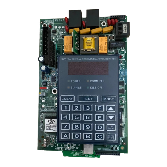
Operating Instructions Normal Mode Seven individual LEDs are provided on the panel as described and shown below: Primary Active - Red LED Secondary Active - (phone line) Red LED (phone line) Four, Seven Segment Displays COMM. FAIL POWER Yellow LED Green LED KISS OFF EIA-485... - Page 51 Normal Mode Operating Instructions The UDACT supervises both telephone lines for proper voltage. A delay of two minutes will occur before a fault in either phone line connection is reported as a trouble. When a fault is detected, the 4 character display will show either “no 1”...
-
Page 52: 4: Key Report Descriptions
Operating Instructions Type Mode NOTE: Where #N represents the number of zones or devices in alarm or trouble. This is valid for all formats except Ademco Contact ID. For all formats, the “general” reports are always transmitted (unless disabled). The zone or point information may follow the general report if enabled. - Page 53 Type Mode Operating Instructions Waterflows Low water pressure Duct detectors Low water level Flame sensor Pump failure Smoke zone NOTE: On the AFP-100 when reporting point information, the factory default for addressable monitor modules is Fire Alarm code 110 and the default for addressable detectors is Smoke Detector code 111.
-
Page 54: 1: Disabling Of Zones Or Points
Operating Instructions Troubleshoot Mode 4.2.1 Disabling of Zones or Points This feature is primarily used when system points have been defined as remote reset, acknowledge, silence or drill switches. Refer to the FACP technical manual for additional information. Activation of remote switches appear as alarms on the EIA-485 bus. The UDACT will report these points as fire alarm points unless disabled in the Type Mode. -
Page 55: Lamp Test Mode
Lamp Test Mode Operating Instructions A handset may be temporarily connected across transformer T1 as indicated below. The handset, when connected across T1, may be used only as an amplifier/speaker or telephone with the UDACT used for number dialing. Transformer Figure 4.3 Handset/Speaker Connection 4.4 Lamp Test Mode This will test all system LEDs. -
Page 56: Section 5: Reporting Formats
Section 5: Reporting Formats 5.1 Data Reporting Structure The table below shows the data reporting structure for each of the pulsed formats as well as the Ademco Express formats. • Ademco Express formats allow a typical data message to be transmitted to the Central Station in under 5 seconds. - Page 57 Data Reporting Structure Reporting Formats Letter codes for Table 5.1 on page 56: SSS or = Subscriber ID SSSS = Alarm (1st digit) = Alarm (2nd digit) = Alarm Restore (1st digit) = Alarm Restore (2nd digit) =Zone Trouble (1st digit) =Zone Trouble (2nd digit) =Zone Trouble Restore (1st digit) RTZ2...
-
Page 58: 1: Ademco Contact Id
Reporting Formats Data Reporting Structure 5.1.1 Ademco Contact ID The reporting structure for the Ademco Contact ID format is as follows: SSSS 18 QXYZ GG CCC SSSS = Four digit Subscriber ID (addresses 17 - 20 and 43 - 46) = Identifies transmission as Contact ID to the receiver at the Central Station = Event Qualifier;... - Page 59 Data Reporting Structure Reporting Formats By using the Type Mode feature, identification of zone/point types is possible. Limits for the maximum number of zones/points reported for each panel are as follows: AFP-100 = 198 points or 56 zones AFP-200 = 99 zones AFP-300 = 256 points or 99 zones AFP-400 = 448 points or 99 zones NFS2-640, NFS-640 = 568 points or 99 zones...
- Page 60 Reporting Formats Data Reporting Structure Maximum FACP Address System 500 AFP-100 AFP-200 System 5000 System 5000 with AIM-200 AFP-300 AFP-400 NFS2-640/NFS-640 NFS-320 AM2020/AFP1010 NCA/NCA-2 NFS-3030/NFS2-3030 Table 5.5 Type Mode Maximum Address UDACT Instruction Manual — P/N 50050:M 12/18/2009...
-
Page 61: Section 6: Compatible Receivers
Section 6: Compatible Receivers 6.1 UL Listed Receivers The chart below shows UL listed receivers compatible with the UDACT: Format # (Addresses 16 & 42) 4+1 Ademco Express 4+2 Ademco Express 3+1/Standard/1800/2300 (5, 6) Not Used 3+1/Standard/1900/1400 Not Used 4+1/Standard/1800/2300 Not Used 4+1/Standard/1900/1400 Not Used... - Page 62 Notes UDACT Instruction Manual — P/N 50050:M 12/18/2009...
-
Page 63: Appendix A: Afp-100 (Ul 8Th)
Appendix A: AFP-100 (UL 8th) A.1 General The UDACT is capable of reporting a maximum of 56 zones or 198 points when used with the AFP-100. For more information on the AFP-100 see the AFP-100 Instruction Manual. A.2 Mounting A.2.1 Internal The UDACT can be mounted in the AFP-100 cabinet by following the instructions and referring to the figure below: Step... -
Page 64: A.2.2: Remote
AFP-100 (UL 8th) Wiring A.2.2 Remote The UDACT can also be mounted remotely using an ABS-8RB or UBS-1 enclosure placed within 6,000 feet (1,828.8 meters) of the control panel. Refer to "Remote Installation" on page 22 for installation instructions. A.3 Wiring CAUTION: Remove all power from the control panel by disconnecting AC and batteries before making any connections to prevent personal and/or circuit damage. - Page 65 Wiring AFP-100 (UL 8th) Below is a remote installation of a UDACT with an AFP-100: Solid Earth To Phone Lines Ferrite Core Ground (supervised) Connection ABS-8R or UBS-1 AFP-100 Circuit Board AFP-100 Cabinet +24V BATT + BATT - +24V RESET COMMON +24V POWER COMMON...
-
Page 66: A.4: Zone Assignments
AFP-100 (UL 8th) Zone Assignments A.4 Zone Assignments Use chart to carefully identify function of each zone in the system. Take special precaution with any supervisory zones in the system. Use Type Mode (refer to "Type Mode" on page 52) to match the function of remaining zones in the system for proper reporting. -
Page 67: A.5: Point Assignments
Point Assignments AFP-100 (UL 8th) A.5 Point Assignments Use chart to carefully identify all points in the system. Take special precaution with any supervisory points and remote switches in the system. Use Type Mode (refer to "Type Mode" on page 52) to match the function of remaining zones in the system for proper reporting. Type of Device Type of Device Type of Device... -
Page 68: Appendix B: Afp-200 (Ul 8Th)
Appendix B: AFP-200 (UL 8th) B.1 General The UDACT is capable of reporting a maximum of 99 zones when used with the AFP-200. For more information on the AFP-200 see the AFP-200 Instruction Manual. B.2 Mounting Since the AFP-200 cannot accommodate the UDACT in the control panel enclosure, the UDACT must be mounted remotely using an ABS-8RB or UBS-1 enclosure placed within 6000 feet (1828.8 meters) of the control panel. - Page 69 Wiring AFP-200 (UL 8th) Below is a remote installation of a UDACT with an AFP-200: Solid Earth To Phone Lines Ground (supervised) Connection Ferrite Core ABS-8RB or UBS-1 AFP-200 Circuit Board AFP-200 Cabinet +24V EARTH ACS/TERM Comm FAILURE RS– +24V SHIELD DO NOT USE TERM...
-
Page 70: B.4: Zone Assignments
AFP-200 (UL 8th) Zone Assignments B.4 Zone Assignments Use chart to carefully identify function of each zone in the system. Take special precaution with any supervisory zones in the system. Use Type Mode (refer to "Type Mode" on page 52) to match the function of remaining zones in the system for proper reporting. -
Page 71: Appendix C: System 500 (Ul 8Th)
Appendix C: System 500 (UL 8th) C.1 General The UDACT is capable of reporting a maximum of 56 zones when used with the System 500. It reports alarms and troubles on inputs and reports only troubles on outputs. Beware of 'gaps' in the reporting of input circuits. - Page 72 System 500 (UL 8th) Wiring Below is a remote installation of a UDACT with a System 500: Solid Earth To Phone Lines Ground (supervised) Connection Ferrite Cores ABS-8RB or UBS-1 System 500 CPU +24V RESET COMMON +24V POWER COMMON BATT+ BATT –...
-
Page 73: C.4: Zone Assignments
Zone Assignments System 500 (UL 8th) C.4 Zone Assignments Use chart to carefully identify function of each zone in the system. Take special precaution with any supervisory zones in the system. Use Type Mode (refer to "Type Mode" on page 52) to match the function of remaining zones in the system for proper reporting. -
Page 74: Appendix D: System 5000 (Ul 8Th)
Appendix D: System 5000 (UL 8th) D.1 General The UDACT is capable of reporting a maximum of 120 zones when used with the System 5000. It reports alarms and troubles on inputs and reports only troubles on outputs. Beware of 'gaps' in the reporting of input circuits. -
Page 75: D.3: Mounting
Mounting System 5000 (UL 8th) D.3 Mounting The UDACT may be mounted in the System 5000 control panel enclosure or be mounted remotely using an ABS-8RB or UBS-1 enclosure placed within 6000 feet (1828.8 meters) of the control panel. Refer to "Remote Installation" on page 22 or "Internal Installation" on page 18 for installation instructions. - Page 76 System 5000 (UL 8th) Wiring Below is a remote installation of a UDACT with a System 5000 using an MPS-24B power supply: Solid Earth Ground To Phone Lines Connection (supervised) Ferrite Cores ABS-8RB or UBS-1 EIA-485 Interface System 5000 +24V RESET COMMON +24V POWER COMMON...
-
Page 77: D.5: Zone Assignments With Aim-200
Zone Assignments with AIM-200 System 5000 (UL 8th) D.5 Zone Assignments with AIM-200 Use chart to carefully identify function of each zone in the system. Take special precaution with any supervisory zones in the system. Use Type Mode (refer to "Type Mode" on page 52) to match the function of remaining zones in the system for proper reporting. - Page 78 System 5000 (UL 8th) Zone Assignments with AIM-200 Zone Assignments with AIM-200 (cont.) Zone Zone Function Zone Zone Function Zone Zone Function Table D.4 Zone Assignments - System 5000 with AIM-200, Table Two UDACT Instruction Manual — P/N 50050:M 12/18/2009...
-
Page 79: D.6: Zone Assignments Without Aim-200
Zone Assignments without AIM-200 System 5000 (UL 8th) D.6 Zone Assignments without AIM-200 Use chart to carefully identify function of each zone in the system. Take special precaution with any supervisory zones in the system. Use Type Mode (refer to "Type Mode" on page 52) to match the function of remaining zones in the system for proper reporting. -
Page 80: Appendix E: Afp-300 & Afp-400 (Ul 8Th)
Appendix E: AFP-300 & AFP-400 (UL 8th) E.1 General E.1.1 AFP-300 The UDACT is capable of reporting a maximum of 99 zones or 256 points when used with the AFP-300. E.1.2 AFP-400 The UDACT is capable of reporting a maximum of 99 zones or 448 points when used with the AFP-400. - Page 81 Wiring AFP-300 & AFP-400 (UL 8th) NOTE: The shield end that is not connected should be insulated to prevent accidental grounding. Do not connect both ends of shield under any circumstance since a ground fault may result. Conduit is recommended for external wire runs. Consult local building codes. Refer to "Specifications"...
-
Page 82: E.4: Type Mode Programming
AFP-300 & AFP-400 (UL 8th) Type Mode Programming Below is an internal installation of a UDACT with an AFP-300/AFP-400: To Phone Lines Connect to CHS-4 (supervised) Chassis CPU-300/400 +24V EARTH ACS/TERM Comm FAILURE RS– MPS-400 +24V SHIELD TERM Rs– DO NOT USE Figure E.2 UDACT and AFP-300/AFP-400 in CAB-3/4 E.4 Type Mode Programming To disable or identify a zone or point in Type Mode (refer to "Type Mode"... -
Page 83: E.5: Event Code/Report Transmission
Event Code/Report Transmission AFP-300 & AFP-400 (UL 8th) E.5 Event Code/Report Transmission Via Ademco Contact ID Format Only E.5.1 For Zone Reporting: Zones 1 - 99 report as zone numbers 01 - 99 E.5.2 For Point Reporting: Loop 1, Modules 101 - 196 report as device numbers 01 - 96 (Report defaults to '110') Loop 2, Modules 201 - 296 report as device numbers 101 - 196 (Report defaults to '110') Loop 1, Detectors 101 - 196 report as device numbers 201 - 296 (Report defaults to '111') Loop 2, Detectors 201 - 296 report as device numbers 301 - 396 (Report defaults to '111') -
Page 84: E.6: Zone Assignments
AFP-300 & AFP-400 (UL 8th) Zone Assignments E.6 Zone Assignments Use chart to carefully identify function of each zone in the system. Take special precaution with any supervisory zones in the system. Use Type Mode (refer to "Type Mode" on page 52) to match the function of remaining zones in the system for proper reporting. -
Page 85: E.7: Point Assignments
Point Assignments AFP-300 & AFP-400 (UL 8th) E.7 Point Assignments Use chart to carefully identify all points in the system. Take special precaution with any supervisory points and remote switches in the system. Use Type Mode (refer to "Type Mode" on page 52) to match the function of remaining zones in the system for proper reporting. - Page 86 AFP-300 & AFP-400 (UL 8th) Point Assignments Point Assignments continued: Point Type of Device: Point Type of Device: Point Type of Device; Point Type of Device: Detectors Loop 1 Detectors Loop 1 Detectors Loop 2 Detectors Loop 2 Do Not Do Not Program Program...
- Page 87 Point Assignments AFP-300 & AFP-400 (UL 8th) Point Assignments continued: Type of Device: Type of Device: Point Point System 5000 System 5000 Output Modules Output Modules NOTE: System 5000 modules may only be disabled using Type Mode. Event Code cannot be altered. Physical location is critical to the point number reported.
-
Page 88: Appendix F: Nfs2-640, Nfs-320, (Ul 9Th) And Nfs-640 (Ul 8Th)
Appendix F: NFS2-640, NFS-320, (UL 9th) and NFS-640 (UL 8th) F.1 General The UDACT is capable of reporting a maximum of 99 zones or 636 points when used with the NFS2-640 or NFS-640, and a maximum of 99 zones and 318 points when used with the NFS-320. F.2 Mounting If the UDACT is not mounted within the cabinet that contains the NFS2-640, NFS-640, or NFS- 320, then it must be mounted remotely in an ABS-8RB or UBS-1 enclosure placed within 6000 feet... -
Page 89: F.3.2: Notes
Wiring NFS2-640, NFS-320, (UL 9th) and NFS-640 (UL 8th) Connect 24VDC filtered, non-resettable power from the CPU-640 TB7 to TB1 terminals 1 and 2 on the UDACT. F.3.2 Notes Ferrite cores, PN 29090, are recommended for all applications. Recommended wire is 12 AWG (3.25mm ) to 18 AWG (0.75mm ), twisted pair, shielded cable. - Page 90 NFS2-640, NFS-320, (UL 9th) and NFS-640 (UL 8th) Wiring Below is an internal installation of a UDACT with NFS2-640/NFS-320: Solid Earth To Phone Lines Ground (supervised) Connection Ferrite Core CPU2-640/ CPU2-640/ CPU-320 TB10 CPU-320 TB11 24VDC nonresettable power +24V EARTH ACS/TERM Comm FAILURE RS–...
-
Page 91: F.4: Type Mode Programming
Type Mode Programming NFS2-640, NFS-320, (UL 9th) and NFS-640 (UL 8th) Below is an internal installation of a UDACT with an NFS-640: To Phone Lines Connect to (supervised) Chassis Ferrite Core CPU-640 TB7 CPU-640 24VDC TB13 nonresettable power +24V EARTH ACS/TERM Comm FAILURE RS–... -
Page 92: F.5: Event Code/Report Transmission
NFS2-640, NFS-320, (UL 9th) and NFS-640 (UL 8th) Event Code/Report Transmission F.5 Event Code/Report Transmission Via Ademco Contact ID Format Only F.5.1 For Zone Reporting: Zones 1 - 99 report as zone numbers 01 - 99 F.5.2 For Point Reporting: NOTE: Loop 2 Reporting is only available for the NFS2-640 and NFS-640. -
Page 93: F.6: Zone Assignments
Zone Assignments NFS2-640, NFS-320, (UL 9th) and NFS-640 (UL 8th) F.6 Zone Assignments Use the following chart to carefully identify the function of each zone in the system. Take special precaution with any supervisory zones in the system. Use Type Mode (refer to "Type Mode" on page 52) to match the function of remaining zones in the system for proper reporting. -
Page 94: F.7: Point Assignments
NFS2-640, NFS-320, (UL 9th) and NFS-640 (UL 8th) Point Assignments F.7 Point Assignments Use the following chart to carefully identify all points in the system. Take special precaution with any supervisory points and remote switches in the system. Use Type Mode (refer to"Type Mode" on page 52) to match the function of remaining zones in the system for proper reporting. - Page 95 Point Assignments NFS2-640, NFS-320, (UL 9th) and NFS-640 (UL 8th) Point Assignments continued: Point Type of Device: Point Type of Device: Point Type of Device: Point Type of Device: Module Loop 1 Module Loop 1 Module Loop 2 Module Loop 2 Table F.3 Point Assignments, NFS2-640, NFS-640, and NFS-320, Part Two UDACT Instruction Manual —...
- Page 96 NFS2-640, NFS-320, (UL 9th) and NFS-640 (UL 8th) Point Assignments Point Assignments continued: Point Type of Device: Point Type of Device: Point Type of Device: Point Type of Device: Module Loop 1 Module Loop 2 Detector Loop1 Detector Loop 1 Not Used Not Used NOTE: Addressable detectors on Loops 1 and 2 may be disabled using Type Mode.
- Page 97 Point Assignments NFS2-640, NFS-320, (UL 9th) and NFS-640 (UL 8th) Point Assignments continued: Point Type of Device: Point Type of Device: Point Type of Device: Point Type of Device: Detector Loop 2 Detector Loop 2 Detector Loop1 Detector Loop 1 NOTE: Addressable detectors on Loops 1 and 2 may be disabled using Type Mode.
- Page 98 NFS2-640, NFS-320, (UL 9th) and NFS-640 (UL 8th) Point Assignments Point Assignments continued: Point Type of Device: Point Type of Device: Point Type of Device: Point Type of Device: Detector Loop 2 Detector Loop 2 Detector Loop1 Detector Loop 2 Not Used Not Used NOTE: Addressable detectors on Loops 1 and 2 may be disabled using Type Mode.
- Page 99 Point Assignments NFS2-640, NFS-320, (UL 9th) and NFS-640 (UL 8th) Point Assignments continued: Point Type of Device: Point Type of Device: Output Module Output Module Table F.7 Point Assignments, NFS-640 Only, Part Six UDACT Instruction Manual — P/N 50050:M 12/18/2009...
-
Page 100: Appendix G: Nca-2 (Ul 9Th) And Nca (Ul 8Th)
Appendix G: NCA-2 (UL 9th) and NCA (UL 8th) G.1 General The UDACT is capable of reporting a maximum of 568 zones or 2040 points when used with the NCA or NCA-2. The first 568 points can be programmed using the Type Mode feature (refer to “Type Mode”... - Page 101 Wiring NCA-2 (UL 9th) and NCA (UL 8th) Below is a remote installation of a UDACT with an NCA: Solid Earth To Phone Lines Ground (supervised) Ferrite Cores Connection ABS-8RB or UBS-1 +24V EARTH ACS/TERM Comm FAILURE RS– +24V SHIELD TERM Rs–...
- Page 102 NCA-2 (UL 9th) and NCA (UL 8th) Wiring Below is a remote installation of a UDACT with an NCA-2 using power supplied by the control panel: Wires in conduit To Supervised Solid Earth CAB-3/4 Series Cabinet Phone Lines Ground EIA-485 (ACS Mode) TB7 on control panel +24 VDC non-resettable power...
-
Page 103: Appendix H: Am2020/Afp1010 (Ul 8Th)
Appendix H: AM2020/AFP1010 (UL 8th) H.1 General The UDACT is capable of reporting up to 2,040 points when used with the AM2020/AFP1010 (1,980 Addressable devices plus 60 zones or 1,800 Addressable devices plus 240 zones) The first 568 points can be programmed using the Type Mode feature (refer to "Type Mode" on page 52). All points greater than 568 can be transmitted only as fire alarm points. -
Page 104: H.3.2: Notes
AM2020/AFP1010 (UL 8th) Wiring H.3.2 Notes Ferrite cores, PN 29090, are recommended for all applications. Recommended wire is 12 AWG (3.25mm ) to 18 AWG (0.75mm ), twisted pair, shielded cable. Connect only one end of shield: a) shield may be connected to cabinet (earth ground) at fire alarm panel, or b) shield may be connected to TB1 Terminal 5 (Shield) at UDACT as shown in Figure H.1. -
Page 105: H.4: Point Assignments
Point Assignments AM2020/AFP1010 (UL 8th) Below is an internal installation of a UDACT with an AM2020/AFP1010 using an MPS-24B main power supply: Connect to CHS-4 To Phone Lines Chassis (supervised) EIA-485 Interface SIB-2048 +24V +24V RESET COMMON +24V POWER COMMON BATT + BATT - EARTH... - Page 106 AM2020/AFP1010 (UL 8th) Point Assignments Point No Point Function Point No Point Function Point No Point Function Point No Point Function Table H.1 Point Assignments - AM2020/AFP1010, Part One UDACT Instruction Manual — P/N 50050:M 12/18/2009...
- Page 107 Point Assignments AM2020/AFP1010 (UL 8th) Point Assignments continued: Point No Point Function Point No Point Function Point No Point Function Point No Point Function Table H.2 Point Assignments - AM2020/AFP1010, Part Two UDACT Instruction Manual — P/N 50050:M 12/18/2009...
- Page 108 AM2020/AFP1010 (UL 8th) Point Assignments Point Assignments continued: Point No Point Function Point No Point Function Point No Point Function Point No Point Function Table H.3 Point Assignments - AM2020/AFP1010, Part Three UDACT Instruction Manual — P/N 50050:M 12/18/2009...
-
Page 109: Appendix I: Nfs2-3030 (Ul 9Th) And Nfs-3030 (Ul 8Th)
Appendix I: NFS2-3030 (UL 9th) and NFS-3030 (UL 8th) I.1 General The UDACT is capable of reporting up to 2,040 points when used with the NFS2-3030/NFS-3030. The first 568 points can be programmed using the Type Mode feature (refer to "Type Mode" on page 52). - Page 110 NFS2-3030 (UL 9th) and NFS-3030 (UL 8th) Mounting Conduit is recommended for external wire runs. Consult local building codes. Refer to "Specifications" on page 13 for power requirements. Below is a remote installation of a UDACT with an NFS-3030 using power supplied by the control panel: Wires in conduit To supervised...
- Page 111 Mounting NFS2-3030 (UL 9th) and NFS-3030 (UL 8th) Below is a remote installation of a UDACT with an NFS-3030/NFS2-3030 using an AMPS-24/E main power supply: Wires in conduit CAB-3/4 Series Cabinet To supervised Solid earth phone lines ground EIA-485 (ACS Mode) TB7 on control panel BB-100 or BB-200 +24V...
-
Page 112: I.3: Point Assignments
NFS2-3030 (UL 9th) and NFS-3030 (UL 8th) Point Assignments I.3 Point Assignments Use the following charts to carefully identify the function of each point in the system. Take special precaution with any supervisory points in the system. For the UDACT to report a supervisory point to the central station, both the FACP and the UDACT must have the point programmed as supervisory. - Page 113 Point Assignments NFS2-3030 (UL 9th) and NFS-3030 (UL 8th) Point Assignments continued: Point No Point Function Point No Point Function Point No Point Function Point No Point Function Table I.2 Point Assignments - NFS-3030/NFS2-3030, Part Two UDACT Instruction Manual — P/N 50050:M 12/18/2009...
- Page 114 NFS2-3030 (UL 9th) and NFS-3030 (UL 8th) Point Assignments Point Assignments continued: Point No Point Function Point No Point Function Point No Point Function Point No Point Function Table I.3 Point Assignments - NFS-3030/NFS2-3030, Part Three UDACT Instruction Manual — P/N 50050:M 12/18/2009...
-
Page 115: Appendix J: Annunciators
Appendix J: Annunciators J.1 General The UDACT is connected to the EIA-485 communication bus. AFM series and LDM series annunciators may also occupy the same bus. Use of a UDACT along with one of the above mentioned annunciators on the same control panel will alter the assignments of the first eight yellow LEDs on the annunciator as follows: J.1.1 AFP-100, AFP-200, and AFP-300/AFP-400 Yellow Annunciator... -
Page 116: J.1.3: Am2020/Afp1010
Annunciators General J.1.3 AM2020/AFP1010 Yellow Annunciator Assignment Assignment Without UDACT With UDACT Programmable System Trouble (less AC loss, batt. & supv.) Programmable Not Used Programmable Program Mode Programmable Supervisory Programmable Not Used Programmable Maintenance Alert (future use) Programmable Low Battery/No Battery Programmable AC Fail Notes:... -
Page 117: Index
Index Numerics 24 VDC 23 backbox 18 NFS-320 19 burglary 52 ABS-8RB 64 remote installation of 22 Ademco 61 CAB-3 Series 17 Contact ID 12 CAB-4 Series 100 Contact ID format 58 CAB-400AA 17 Contact ID Reporting Structure 58 CAB-500 17 Express 12 cabinet 13 Express formats 52... - Page 118 D–M Index telephone line 50 idle time 28 installation internal 17 DC Power 13 remote 17 delay 51 internal installation dial tone 12 AFP-300/400 82 document sources 10 AM2020/AFP1010 105 NCA 101 NFS2-640 90 earth ground 13 NFS-640 91 EEPROM 28 EIA-485 12 J16 connector 63 enter/store...
- Page 119 Index N–R Normal 48 Installation Options 17 Program 36 panel ID 34 Troubleshoot 54 Schematic 89 Type 52 NFS-320 Installation Manual 10 mode key 28 NFS-640 25 Modes 48 Installation Options 17 modular jacks 12 panel ID 34 module slot position Schematic 90 System 5000 74 NFS-640 Installation Manual 10...
- Page 120 S–V Index AM2020/AFP1010 104 panel ID 34 NCA 101 schmatic 76 NCA-2 102 System 5000/AIM 33 NCA-2/AMPS-24 102 panel ID 34 NFS2-3030 110 NFS2-640 89 NFS-3030 110 telephone NFS-3030/NFS2-3030/AMPS-24 111 company 14 NFS-320 89 handset 55 NFS-640 90 jacks 24 System 500 72 line testing 16 System 5000 76...
- Page 121 Index W–Z wiring entering 27 exiting 27 nonpower-limited 27 power limited 27 Relay Driver 25 zone 32 zone number 53 zone reporting 33 zone trouble 25 UDACT Instruction Manual — P/N 50050:M 12/18/2009...
- Page 122 Z–Z Index UDACT Instruction Manual — P/N 50050:M 12/18/2009...
- Page 123 Manufacturer Warranties and Limitation of Liability Manufacturer Warranties. Subject to the limitations set forth herein, Manufacturer warrants that the Products manufactured by it in its Northford, Connecticut facility and sold by it to its authorized Distributors shall be free, under normal use and service, from defects in material and workmanship for a period of thirty six months (36) months from the date of manufacture (effective Jan.
- Page 124 World Headquarters 12 Clintonville Road Northford, CT 06472-1610 USA 203-484-7161 fax 203-484-7118 www.notifier.com...