Table of Contents
Advertisement
Advertisement
Table of Contents

Related Manuals for Honeywell HWF2V-COM


Summary of Contents for Honeywell HWF2V-COM
- Page 1 800-24452 9/18 Rev B...
-
Page 2: Table Of Contents
Table of Contents General Information ............................... 1 Package Contents ..............................1 Compatible Fire Panels ............................. 1 Operation ..................................1 Installation ..................................1 UL Compliance................................1 Programming for UL864 Compliance ..........................2 STEP 1 – Determine the Signal Strength and Select a Location ................2 STEP 2 –... -
Page 3: General Information
In addition, the communicator’s power module (PowerBoost1) monitors and reports AC power loss, and low battery conditions. All signals from the HWF2-COM communicator panel are delivered to Honeywell's AlarmNet Net- work Control Center, which routes the information to the appropriate central station. -
Page 4: Programming For Ul864 Compliance
Programming for UL864 Compliance The HWF2-COM Commercial Fire Alarm Communicator provides a programmable supervision feature that allows the system to meet the UL864 Commercial Fire requirements. These requirements are in the following table. NOTICE TO USERS, INSTALLERS, AUTHORITIES HAVING JURISDICTION AND OTHER INVOLVED PARTIES This product incorporates field programmable software. -
Page 5: Step 2 - Mount And Wire
STEP 2 – Mount and Wire • For UL compliant installations, refer to the topic on UL Compliance in this manual. For UL compliant installations, the Telco line wiring and the Power Transformer wiring must be routed • through conduit. For Dry/Indoor use only. - Page 6 12. Ensure the following: LED Display board is fully seated. • • All wiring terminals and connectors are tight. All wiring has been completed and secured with cable ties. • 13. Install the battery (not supplied). Plug the power transformer in, and attach the battery cable. Wiring for Grounds, Power, and RF...
-
Page 7: Step 3 - Program The Communicator
STEP 3 – Program the Communicator The HWF2-COM requires an AlarmNet account. For new installations, please obtain the account information from the central station prior to programming. You can program the communicator by one of the following methods: Using the AlarmNet 360 website. •... -
Page 8: Setting Factory Defaults
This prompt appears only if comm. path includes IP&Cell or IP. IP Flt Time Enter the time delay (1 – 60) in minutes before the communicator notifies the con- (60 mins) trol panel that there is a communication path failure to AlarmNet over the hard- NOTE: Refer to table above wired Ethernet connection. -
Page 9: Step 4 - Register The Communicator With Alarmnet
STEP 4 – Register the Communicator with AlarmNet Once you have programmed the communicator, it must be registered to enable the AlarmNet account. Registering the communicator activates the account with AlarmNet and enables the security system's control panel to send reports. You can register by using one of the following methods: •... -
Page 10: Replacing An Existing Communicator
Possible Errors Displayed if no response to the registration request is received. Registration BAD Timed Out Indicates the city, central station, or customer number for the labeled Registration BAD account(s) is not accepted. The ID information was either entered in- correctly, or the central station failed to pre-authorize programmed ID Pri Sub ID BAD numbers with AlarmNet customer service. -
Page 11: Register By Phone
If you entered an invalid PIN, the appropriate message is displayed Registration BAD depending on which account number is being replaced (see above for exact wording). The registration process is repeated. NOTE: Each attempt causes a substitution alarm to be sent to the cen- tral station. -
Page 12: Dialer Capture Module Information
Dialer Capture Module Information LED Indicator STATUS RED – Steady ON Messages exist in buffer. RED – Flashing No messages to be sent. Waiting for messages. GREEN – Steady ON Normal Indication. GREEN – Blinks every 2 sec. PowerBoost1 communication problem. GREEN –... -
Page 13: Programmer Keyboard Commands
Programmer keyboard commands can be used to quickly view your connectivity settings and options. Most commands require you to press the [Shift] key and then the designated command key. (See the keys desig- nated in red on the 7720P Programming Tool.) Software Revision HWF2V-COM "x.x.xx" indicates the installed software Revision. x.x.xx mm/dd/yy Mm/dd/yy indicates month, day and year of the revision. -
Page 14: Cellular Status Displays (Appear Only If The Communication Path Includes Cell)
NOTE: The following displays except Encryption Test are displayed only if the communication path includes IP. Network Diagnostics Display Physical Link Indicates whether the device has detected a physical connection Good/Bad to the internet. Press the [Space] key to go to the next field. IP Information Display NIC IP Address Displays the IP address assigned to this device. -
Page 15: Lte Displays
LTE Displays Signal Display for LTE RAT RSRP RSRQ RAT – Radio Access Technology. xxxx xxxx RSRP – Reference Signal Received Power RSRQ – Reference Signal Received Quality Press the [space] key to get to the next screen. Press the [backspace] key to go to the previous field. Min/Max Signal Display for LTE RSRP MIN RSRP –... - Page 16 Operating with 3G service (Applies to HWF2A ONLY) Signal Display for 3G RAT RSCP EC/No RAT – Radio Access Technology. -xxx -xxxxxx RSCP –Received Signal Code Power Ec/N0 – Carrier Noise Ratio (CNR) Press the [space] key to get to the next screen. Press the [backspace] key to go to the previous field.
-
Page 17: System Status Displays
System Status Displays ECP Mode Displays system fault status. Flt: Represents radio faults • OK: Normal, No fault • I: No network connectivity over IP and fault time has expired i: No network connectivity over IP and fault time has yet expired. -
Page 18: Running Network Diagnostics
Running Network Diagnostics (available only if the communication path includes IP) The network diagnostic process tests the integrity of the links between the communicator and the various connection points of AlarmNet Control that are known as "Redirects" (Redirs or RDR). To initiate the network diagnostics, press the [F] key on the 7720P Programming Tool. -
Page 19: Possible Errors Running Network Diagnostics
Possible Errors Running Network Diagnostics Errors may occur either while tracing the connection to a given Redir or while testing the service at a given Redir. The following list highlights the most common errors. Please contact the AlarmNet Technical Assis- tance Center (TAC) for help regarding any errors NOT listed below: Possible Errors While tracing the connection to Redir x, the trace fails before ever reach-... -
Page 20: Powerboost1 Information
PowerBoost1 Information LED Indicator STATUS AC (green) AC power available. ACTIVE (green) Cyclical flashing – normal communications. Repetition of 3 flashes – loss of communications. LOW BATT (yellow) Missing or low battery. TROUBLE (yellow) One or more trouble conditions exist, such as; overload, output supervision, ground fault, or charger failure. -
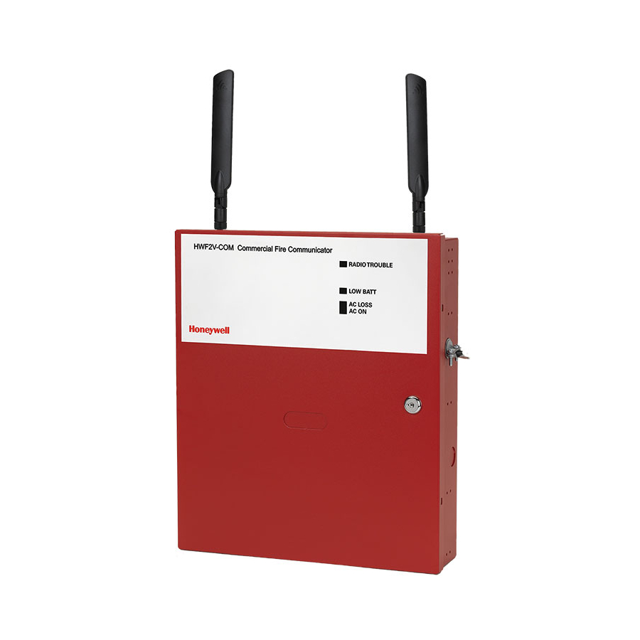
Page 21: Communicator Information
Communicator Information... -
Page 22: Rf Specifications
RF Specifications Frequency Bands WCDMA WCDMA Band 2 Band 4 Band 5 Band 12 Band 13 Band II Band V HWF2V HWF2A Output Power Class 3 23dBm WCDMA Class 3 24dBm IMPORTANT NOTE ABOUT EXTERNAL ANTENNAS Antenna may only be installed or replaced ONLY by a professional installer. TO THE INSTALLER HW2FA-COM: The external antenna gain shall not exceed 6.63 dBi for 700 MHz and 850MHz, 6.00 dBi for 1700 MHz, and 8.51 dBi for 1900 MHz. -
Page 23: Hwf2-Com Trouble Detection Information
Transformer: N8167 or Primary – 120VAC, 60Hz, Secondary – 18VAC, 50VA N8167-1 Battery: 12V, 7Ah sealed lead acid type (not supplied) Use a Honeywell 712BNP, Yuasa NP7-12 or equivalent. Battery Charging Current: maximum 1A Battery Discharge Current: standby 210mA, active 290mA Environment: Operating temperature: 0ºC to +49ºC... - Page 24 NOTES...
- Page 25 NOTES...
- Page 26 NOTES...
- Page 27 • All circuits are power limited except the backup battery which is non-power limited. • Non-power limited wiring must be separated from the power limited wiring by at least 1/4 inch. • If desired, use a Honeywell 955WH Tamper Switch with the 28-2 bracket.
- Page 28 HONEYWELL POWER SUPPLY SUPPORT AND WARRANTY Documentation and online support: Please go to http://www.honeywellpower.com Contact Technical Support: (877) HPP-POWR, or Email us at hpp.techserv@honeywell.com Warranty: For the latest warranty information, please go to: https://www.security.honeywellhome.com/hsc/resources/wa/index.html...