
Related Manuals for Panasonic ER-X Series


Summary of Contents for Panasonic ER-X Series
- Page 1 Pulse AC Method Area Ionizer ER-X SERIES * The contents of this catalog are as of October 2017. 2022.7 For the latest information, please visit our company website.
- Page 2 "Fast Charge Removal", "Airless", "Low-Pressure". Three charge removal modes for diverse application coverage The ER-X series offers an airless charge removal capability to eliminate the need for compressed air in addition to low pressure and high speed compressed air based modes. Furthermore, it supports dual-head configurations for expanded application coverage.
- Page 3 Area Ionizer Pulse AC method for faster charge removal Automatic ion balance control The ER-X series has adopted the pulse AC method The ER-X series provides an automatic ion balance that alternately applies positive and negative voltages control mechanism that senses the amount of ions being to each discharge needle.
- Page 4 Additionally, by using separate air sources design* . The ER-X series can be embedded in, or for the discharge needle barrier and ion transport, the retrofitted onto, equipment that did not provide enough ER-X series keeps discharge from becoming unstable space for antistatic measures in the past.
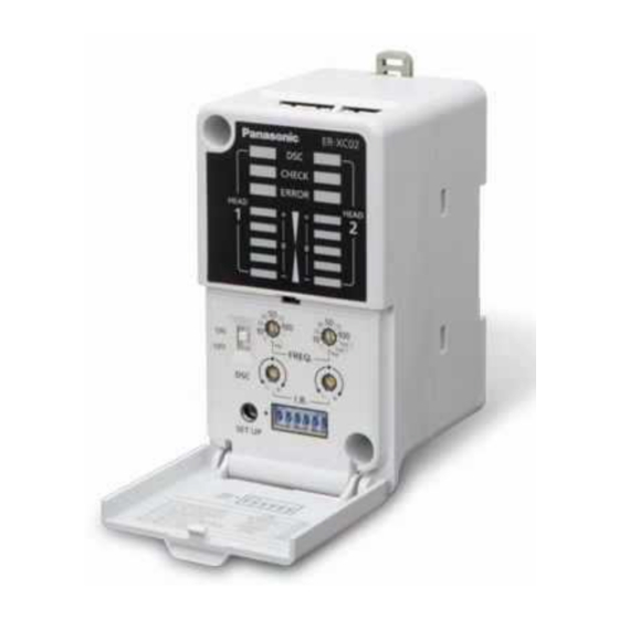
- Page 5 ER-X SERIES Area Ionizer CONTROLLER Dual head configuration for enhanced charge area and layout expansion heads controller • Different heads can be combined. * The new-type controller, ER-XC02, allows simultaneous connection of the bar type head and spot type head. •...
- Page 6 ER-X SERIES Area Ionizer APPLICATIONS Preventing electrostatic damage High-speed charge removal on a Airless charge removal of minute components during bonding taping machine on a conveyor belt Removal of static charges on laminate film Prevention of part feeder clogging High-speed charge removal on FPCs Charge removal and dust removal Charge removal of molded plastic Charge removal and dust removal of...
-
Page 7: Order Guide
ER-X SERIES Area Ionizer ORDER GUIDE Head connection cable is not supplied with the head. Please order it separately. Heads Charge removal time Effective charge Type Appearance Ion balance Model No. (±1,000 V→±100 V) removal width 0.3 sec. or less ER-X001 (Note 1), 50 mm... - Page 8 ER-X SERIES Area Ionizer ORDER GUIDE Controller Please order power cable or AC adapter separately. Number of heads Type Appearance Model No. Output connected Standard ER-XC02 Max. 2 units PhotoMOS relay type Head connection cables Head connection cable is not supplied with the head. Please order it separately. Appearance Model No.
-
Page 9: Specifications
ER-X SERIES Area Ionizer SPECIFICATIONS Heads Type Spot type Bar type Item Model No. ER-X001 ER-X008 ER-X016 ER-X032 ER-X048 ER-X064 CE marking directive compliance EMC Directive, RoHS Directive Effective charge removal width 50 mm 1.969 in approx. 80 mm 3.150 in approx. - Page 10 ER-X SERIES Area Ionizer SPECIFICATIONS Allowable ambient temperature of high and low temperature resistant type head ER-X□HC and its installation When installing, make sure to expose a section measuring 500 mm 19.685 in or more to the normal temperature area as shown below for the protection of the high-voltage unit.
- Page 11 ER-X SERIES Area Ionizer CHARGE REMOVAL CHARACTERISTICS (TYPICAL) Please contact our office for details on data that is not listed here. Measured using a 150 × 150 mm 5.906 × 5.906 in CPM (charge plate monitor). (At center of CPM) Common to ER-X001/X008 ER-X001 Air flow...
- Page 12 ER-X SERIES Area Ionizer CHARGE REMOVAL CHARACTERISTICS (TYPICAL) Please contact our office for details on data that is not listed here. Measured using a 150 × 150 mm 5.906 × 5.906 in CPM (charge plate monitor). (At center of CPM) ER-X008 Charge removal field Charge removal field...
- Page 13 ER-X SERIES Area Ionizer CHARGE REMOVAL CHARACTERISTICS (TYPICAL) Please contact our office for details on data that is not listed here. Measured using a 150 × 150 mm 5.906 × 5.906 in CPM (charge plate monitor). (At center of CPM) Common to ER-X016/X032/X048/X064 ER-X032 Charge removal field...
- Page 14 ER-X SERIES Area Ionizer CHARGE REMOVAL CHARACTERISTICS (TYPICAL) Please contact our office for details on data that is not listed here. Measured using a 150 × 150 mm 5.906 × 5.906 in CPM (charge plate monitor). (At center of CPM) ER-X064 Charge removal field Charge removal field...
- Page 15 ER-X SERIES Area Ionizer I/O CIRCUIT AND WIRING DIAGRAMS New-type controller (produced from April 2014 on) Notice: Products manufactured from April 2014 and before April 2016 cannot be used with the high and low temperature resistant type head ER-X008HC. For the Identification of previous-type and new-type controllers and for the combination with the head, refer to p.16.
-
Page 16: Precautions For Proper Use
ER-X SERIES Area Ionizer PRECAUTIONS FOR PROPER USE • When using as a CSA and UL compliant product, use a CLASS 2 CSA/ • Never use this product as device for personnel protection. UL certified power supply, or a CSA/UL certified power supply that •... - Page 17 ER-X SERIES Area Ionizer PRECAUTIONS FOR PROPER USE Mounting Controller installation Angle • Mount the controller on a 35 mm 1.378 in width DIN rail or using Head installation adjustment screw M4 screws. • Using two M4 screws or one M6 screw, screw <When mounting on a DIN rail>...
- Page 18 ER-X SERIES Area Ionizer DIMENSIONS (Unit: mm in) The CAD data can be downloaded from our website. ER-X008/X016/X032/X048/X064 Head Joint for ø6 ø0.236 air tube 28.5 1.122 28.5 ø6.9 ø0.272 high-voltage cable 0.5 m 1.640 ft 1.122 0.370 0.236 7.087 0.370 2-ø6.5 ø0.256...
- Page 19 ER-X SERIES Area Ionizer DIMENSIONS (Unit: mm in) The CAD data can be downloaded from our website. ER-X001 Head 28.5 ø10.5 ø0.413 high-voltage cable 1.2 m 3.937 ft long 1.122 (internal air tube) 0.472 M3 fixing screw 0.339 0.787 0.630 0.236 8.268 0.787...
- Page 20 Disclaimer The applications described in the catalog are all intended for examples only. The purchase of our products described in the catalog shall not be regarded as granting of a license to use our products in the described applications. We do NOT warrant that we have obtained some intellectual properties, such as patent rights, with respect to such applications, or that the described applications may not infringe any intellectual property rights, such as patent rights, of a third party. Panasonic Industry Co., Ltd. Industrial Device Business Division 7-1-1, Morofuku, Daito-shi, Osaka 574-0044, Japan industrial.panasonic.com/ac/e/ Specifications are subject to change without notice. ⓒ Panasonic Industry Co., Ltd. 2022.7 Printed in Japan...