Table of Contents
Advertisement
Quick Links
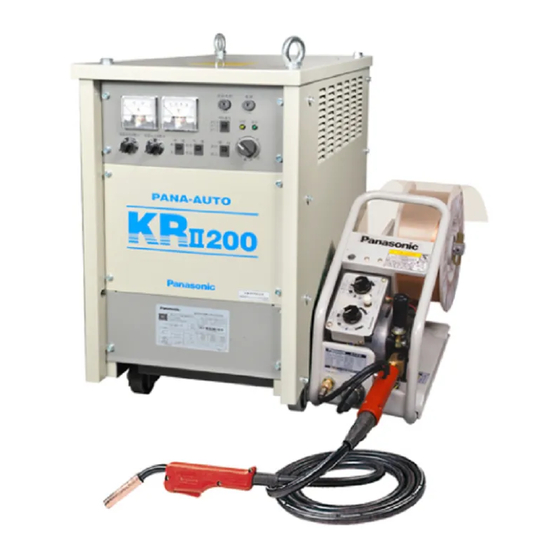
Thyristor Controlled MIG/MAG Arc Welding Power Source
● Thank you for your purchase of Panasonic welding power source.
● Before operating this product, please read the instructions carefully and save this
manual for future use. First of all, please read "Safety precautions" or "Safety
manual".
● SPEC. No.:YD-500KR2HJG
Panasonic Welding Systems (Tangshan) Co., Ltd.
Operating Instructions
Model No.
YD-200KR
YD-350KR
YD-500KR
TSM80227-05
Advertisement
Table of Contents

Related Manuals for Panasonic YD-200KR


Summary of Contents for Panasonic YD-200KR
- Page 1 Model No. YD-350KR YD-500KR ● Thank you for your purchase of Panasonic welding power source. ● Before operating this product, please read the instructions carefully and save this manual for future use. First of all, please read “Safety precautions” or “Safety manual”.
-
Page 2: Table Of Contents
C0NTENTS PREPARATIONS INSTALLATION FLACE AND POWER FACILITY ………………………………………………………………… 1 OVERALL CONNECTION DIAGRAM OF EQUIPMENT ………………………………………………………………3 CO N N E C T 1 0 N … … … … … … … … … … … … … … … … … … … … … … … … … … … … … … … … … 4 We l d i n g Po w e r So u r c e an d Sw i t c h Bo x …... - Page 3 WARNINGS AND CAUTIONS FOR SAFETY For your safety, be sure to observe the following. ■ ! Warning! In Order to Avoid Serious Accident Result in Injury or Death Carry Out Grounding Work: In order to prevent you from getting an electric shock, carry out grounding work provided by the law.
- Page 4 NOTICE . Machine export to Europe This product does not meet the requirements specified in the EC Machinery Directive which is the EU safety ordinance that will be enforced starting on January 1 , 1995. Please bear in mind that this product may not be brought as is into the EU after January 1, 1995. The same restriction also applies to any country which has signed the EEA accord.
- Page 5 INSTALLATION PLACE AND POWER SOURCE FACILITY PREPARATIONS Installation Place Avoid the direct sunshine and rain, and install in Do not install in a place where a metallic foreign an indoor place with less humidity and dust. substance may enter inside the welding source. (Indoor ambient temperature -10 to 40℃) Install the welding source 20cm or more away from the Install in a place where welding arc is not exposed...
- Page 6 YD-500KR2 Power source YD-500KR2HD□ YD-500KR2HG/N□ YD-500KR2HK□ YD-500KR2HJ□ 3-Phase 220V 3-Phase 380V 3-Phase 440V 3-Phase 415V Frequency 50/60Hz (Switchable on the printed circuit board) Commercial power 40kVA Facility source capacity Engine generator Twice large than 31.9 kVA with compensating winding. Primary line current Approx.
-
Page 7: Preparations
OVERALL CONNECTION DIAGRAM OF EQUIPMENT PREPARATIONS The following figure shows a connection diagram for our standard component units. The crosshatched units are to be prepared by the customer. The non-crosshatched units may be altered according to a customer's request or separately arranged. - Page 8 CONNECTION PREPARATIONS Welding Source Switch Box Safety Warning Be sure to observe the following in order to avoid a burn or an accident resulting in injury or death. Prior to connection work, be sure to turn off the switch of the switch box and make sure or safety.
-
Page 9: Welding Power Source And Output Side
CONNECTION (CONTINUED) PREPARATIONS Welding Power Source and Output Side ①Turn off the power switch. ③Open upward the terminal cover located at the lower part of the operation.(after completing connections, connect the wire feed control cable to the plug socket shown on the next page and Terminal cover put back the terminal cover) ④Using an accessory... -
Page 10: Welding Power Source And Wire Feeder
CONNECTION (CONTINUED) PREPARATIONS Welding Power Source and Wire Feeder Caution Be sure to use this power source in combined with a specified feeder. Welding is not allowed with a non-specified power source or when combined with a non-specified wire feeder. Erroneous use may damage the equipment. ①... -
Page 11: Connecting The Gas Regulator
CONNECTION (CONTINUED) PREPARATIONS Connecting the Gas Regulator Warning for Safety This is a high-pressure gas device. Erroneous handling could endanger your safety such as being directly struck by a gas bomb due to a high-pressure gas. Prior to connecting it, be sure to read its instruction manual. -
Page 12: Component Units And Their Functions
COMPONENT UNIT AND THEIR FUNCTIONS PREPARATIONS Welding Power Source(Operation Panel) Ammeter Wire Diameter Selector Switch Select a desired wire diameter according to Indicates a welding current your need. value. Note) The figure shows the switch for the Refer to n0te) at the lower YD-200KR2 and YD-350KR2. - Page 13 FEEL SAFE TO USE IT. PREPARATIONS Welding power source Crater Voltage Control Crater Current Control When “CRATER ON” is selected with the crater selector When “CRATER ON” is selected with switch, you can control a crater welding voltage. Note) the crater selector switch, you can When SIMPLE UNIFIED is selected (refer to pages 25 and control a crater welding current...
-
Page 14: Remote Controller
FEEL SAFE TO USE IT. PREPARATIONS REMOTE CONTROLLER The remote controller is fixed to the wire feeder. Scale Plate Pressing this switch feeds the welding wire. Both sides of the plate is used properly, Although a feed rate can he adjusted with the depending type setting;... -
Page 15: Checks And Preparations Frior To Operation
CHECKS AND PREFARATIONS PRIOR TO OPERATION BASICS Wearing the Safety Protective Gear Safety Protective Gear Wear leather gloves and safety shoes, and protect the eyes and exposed parts of your body. Prepare a protective welding mask with light-shielding filter plate. ... -
Page 16: Ad J U S T I N G T He Ga S Fl O W Ra T
CHECKS AND PREFARATIONS PRIOR TO OPERATION BASICS Adjusting the Gas Flow Rate ③Set the GAS SUPPLY switch to CHECK. ④Set the GAS SUPPLY switch to WELD. Turn on the switch Switch Box the switch box. Welding Power Source ②Turn on the POWER switch ④Open the main valve of the gas bomb. -
Page 17: A T T A C H I N G T H E W E L D I N G W I R
CHECKS AND PREFARATIONS PRIOR TO OPERATION BASICS Attaching the welding wire ⑩Put back a pressure arm and pressure nut in that order. Attach a feed roller in direction which allows you to see the same numeral as the wire diameter used. -
Page 18: Feeding The Wire By Inching Operation
CHECKS AND PREFARATIONS PRIOR TO OPERATION BASICS Feeding the Wire by Inching Operation Hold Down the inching switch to feed the wire and release it when the wire comes out of the tip of the welding torch about 15 to 20 mm. Caution Feed a fine-diameter wire (0.9) slowly because it buckles easily. -
Page 19: Welding By Manual Operation
WELDING BY MANUAL OPERATION BASICS The following two kinds of welding are allowed by operating the “CRATER ON/OFF” selector switch on the operation panel and the torch switch. Be sure to read “Duty cycle” on Page 20, and observe a duty cycle in using the equipment. Using only this switch allows start/stop operation. -
Page 20: Welding With Crater Control Disabled
WELDING BY MANUAL OFERATION BASICS Welding with crater control disabled (torch switch synchronous operation) This welding is mainly used for tack welding,, repeated short welding or thin-plate welding. Operation Procedure Set the CRATER “ON/OFF” selector switch to "OFF" and turn on/off the torch switch. Synchronized with it, welding arc starts or stops. -
Page 21: Duty Cycle
DUTY CYCLE BASICS 60%(155A or less) Rating YD-200KR (Service Range) 50 100 Welding Current (A) 60%(248A or less) Rating YD-350KR (Service Range) 60 100 300 350 400 Welding Current (A) 60%(387A or less) Rating YD-500KR (Service Range) 60 100 Welding Current (A) ... -
Page 22: Applications
EXTENDED FUNCTIONS APPLICATIONS The extended functions refer to the altered and expended forms or various basic functions and performances set and specified upon shipment, including the basic welding control sequence described so far. Connecting the Extension Cable (Extension Cable is Optional) If an extension cable is connected between the plus(+)-side output terminal of the welding power unit and the output cable of the wire feeder, the scope of welding work can be expanded. - Page 23 EXTENDED FUNCTIONS APPLICATIONS Switch and Controls on the Printed Circuit Board Tips When the front panel is removed, you can find various switches (connectors) and controls on the printed circuit board as well, which are available for extending many different functions.
-
Page 24: Setting The Selector Switches On The Printed Circuit Board
EXTENDED FUNCTIONS APPLICATION Layout of Switches and Controls on Printed Circuit Board Changeover Caution:To change over the setting of the SW11,and from the SW8 and vice SW6 to versa.change an inserted position of a white connector. Setting the Selector Switch on the Printed Circuit Board. ... - Page 25 EXTENDED FUNCTIONS APPLICATIONS Self-hold Crater Operation with Initial Condition Function(SW6 Selected) This is the same as “general self-hold crater operation” described in [BASICS] in that it is a welding control sequence which assumes twice on/off operation of the torch switch to be one cycle. What differs from “general self-hold crater operation”...
- Page 26 EXTENDED FUNCTIONS APPLICATIONS Selector Switch 10 (SIMPLE UNIFIED/INDIVIDUAL) --- Set to INDIVIDUAL upon shipment INDIVIDUAL --- This mode sets both welding current and voltage to INDIVIDUAL. SIMPLE UNIFIED --- When a welding current is selected with the output regulator on the remote controller, the SIMPLE UNIFIED mode takes place ,where an almost corresponding welding voltage is automatically set.
-
Page 27: A D J U S T I N G T H E C O N T R O L S O N T H E P R I N T E D C I R C U I T B O A R
EXTENDED FUNCTIONS APPLIATIONS Adjusting the Controls on the Printed Circuit Board The following control functions are incorporated In this machine in order to improve weldability. They will work regardless of the settlings/operations of various switches on the welding power unit operation panel. -
Page 28: For Your Information
(consumable) parts of the welding torch and wire feeder, and clean or replace the parts as required. For replacement parts, be sure to use those purely designed for the PANASONIC welding machines in order to maintain performance and functionality. -
Page 29: Cable
DAILY INSPECTION FOR YOUR INFORMATION Cables Block Inspection Point Remarks Causes a wire feed failure Too much bent of the torch cable Causes winking of arc due to scooping wire feed or unstable arc generation Torch cable ... -
Page 30: P E R I O D I C I N S P E C T I O
These lives depend on the machine operating condition at customer's site and cannot be precisely stated. In periodic inspection, assume that they are a kind of consumable parts. For replacement parts, be sure to use those purely designed for the PANASONIC welding machines in order to maintain performance and functionality. - Page 31 PERIODIC INSPECTION FOR YOUR INFORMATION Removal of the Top Plate and Side Plate. ①Remove of the top plate. (4 bolts) ②Remove the side plates. (9 bolts each on the left and right) Tips Cautions for Dielectric Strength Test and Insulation Resistance Test Since this machine uses many semiconductors, including thyristors, an imprudent dielectric strength test or insulation resistance measurement could lead to a trouble of the equipment.
-
Page 32: Initial Trouble Diagn0Sis
INITIAL TROUBLE DIAGNOSIS FOR YOUR INFORMATION Even if you have a trouble such as being unable to weld, unstable arc, bad welding result, do not jump to the hasty conclusion that the welding machine is out of order. Even if the welding machine has nothing wrong, the above-mentioned errors may occur because or something far from a trouble, for example, blown or loosened fuse, unset or erroneously set switches, almost disconnected cable, cracked gas hose. - Page 33 INITIAL TROUBLE DIAGNOSIS FOR YOUR INFORMATION Error Block and check item Adaptability of the feed Roller and SUS tube wire Diameter Crack, choked groove, or tipping of ○ ○ ○ ○ ○ Wire feeder the feed roller ...
- Page 34 OTHER TROUBLE AND ERROES FOR YOUR INFORMATION When you have a trouble or error other than those mentioned in INITIAL TROUSLE DIAGNOSIS, determine which one of the following categories it belongs to. Following a relevant flow chart, make an appropriate check. ...
- Page 35 OTHER TROUBLE AND ERROES FOR YOUR INFORMATION When the power switch of the welding machine is turned on, but the POWER indicator lamp does not go on 3-phase rated voltage being applied to Is the switch of the the input end of the switch box turned on ? welding power unit ? Is the switch of the...
- Page 36 OTHER TROUBLE AND ERROES FOR YOUR INFORMATION When output suddenly stops during welding(while arc is being produced) wire Has the chip melted Is the Warn. Indicator turning on the torch and stuck to the wire? lamp [22] turned on? switch? ...
-
Page 37: T R O U B L E S H O O T I N
OTHER TROUBLE AND ERROES PREPARATIONS Trouble shooting Warning for safety Prior to troubleshooting, be sure to turn off the switch box and welding machine and make sure of safety. Otherwise, it may lead to a serious accident affecting safety or the human body, such as electric shock or burn. - Page 38 AFTER-SALE SERVICE PREPARATIONS When asking for repair For welding errors, check by yourself, following the Initial diagnoses List on pages 32 and 33. When you need a repair, please contact our dealer where you purchased the equipment, or our branch office.
- Page 39 APART LAYOUT DRAWING The part specifications shown in figure is required to refer the attached parts list. Front Right Side Rear Left Side ○ 35...
- Page 40 AFTER-SALE SERVICE The part specifications shown in figure is required to refer the attached parts list. Front Right Side Rear Left Side ○ YD-500KR2 36...
- Page 41 PARTS LIST ( The No. of the table shows the location number of Parts Layout Drawing) (Spec. No.YD-200KR2) Symbol Name Code No.of Code No.of Code No.of Q’ty Remarks YD-200KR2HDE YD-200KR2HGF YD-200KR2HJE Mtr(Tr1) Main transformer TSM94798 TSM94824 TSM94823 Control transformer UTU19690 UTU19410 DLX00023 Reactor ass’y...
- Page 42 PARTS LIST ( The No. of the table shows the location number of Parts Layout Drawing) (Spec. No.YD-350KR2) Symbol Name Code No.of Code No.of Code No.of Code No.of Q’ty Remarks YD-350KR2HDE YD-350KR2HGG YD-350KR2HKE YD-350KR2HJE Mtr(Tr1) Main transformer TSM94432 TSM94562 TSM94598 TSM94605 Control transformer UTU19690...
- Page 43 PARTS LIST ( The No. of the table shows the location number of Parts Layout Drawing) (Spec. No.YD-500KR2) Symbol Name Code No.of Code No.of Code No.of Code No.of Q’ty Remarks YD-500KR2HDE YD-500KR2HGJ YD-500KR2HJE YD-500KR2HKF Mtr(Tr1) Main transformer TSM94842 TSM94849 TSM94856 TSM94561 Control transformer UTU19690...
- Page 44 CRCUIT DIAGRAM YD-200/350KR2...
-
Page 45: C I R C U I T D I A G R A
CIRCUIT DIAGRAM YD-500KR2... -
Page 46: O U T S I D E D R A W I N
OUTSIDE DRAWING YD-200KR2 YD-350KR2 YD-500KR2... - Page 47 GLOSARY FOR YOUR INFORMATION What is Crater Except welding with a very low current, there generally occurs a concave at the end of welding. This concave is referred to as a crater; it reminds you of a crater on the moon surface. Welding arc The crater results from a push-down force by arc Welding bead...
- Page 48 GLOSARY FOR YOUR INFORMATION What is Simple Unification Adjustment? Selection of the welding current with the output regulator on the remote controller. "Simple unification" adjustment refers to adjustment which automatically selects the welding voltage almost commensurate with that welding current. ...
- Page 49 EXAMPLE OF WELDING CONDITIONS FOR YOUR INFORMATION welding conditions list(Reference) The following list gives you reference values of standard welding conditions. In actual welding work, it is necessary to alter them in compliance with a shape of weld assembly and welding posture to obtain appropriate conditions. Plate Wire Route Gap...
-
Page 50: R A T I N G S A N D S P E C I F I C A T I O N
RATINGS AND SPECIFICATIONS YD-200KR2 Power source YD-200KR2HD□ YD-200KR2HG/N□ YD-200KR2HK□ YD-200KR2HJ□ 3-Phase 220V 3-Phase 380V 3-Phase 440V 3-Phase 415V Frequency 50/60Hz (Switchable on the printed circuit board) Rated input 7.6kVA,6.5kW Rated output current DC 50~200A Rated output volt. DC 15~25V Solid wire (mild steel) Applicable wire dia. - Page 51 Panasonic Welding Systems (Tangshan) Co., Ltd. Add:Tangshan New & Hi-Tech Development Zone,Hebei,China TEL: +86-0315-3206017 (3206066) FAX: +86-0315-3206070 (3206018) POST CODE:063020 2017.09...