NETGEAR ProSafe GS110TP Hardware Installation Manual
Smart poe switch
Hide thumbs
Also See for ProSafe GS110TP:
- Software administration manual (269 pages) ,
- Installation manual (2 pages) ,
- User manual (29 pages)

Related Manuals for NETGEAR ProSafe GS110TP


Summary of Contents for NETGEAR ProSafe GS110TP
- Page 1 GS110TP Hardware Installation Guide NETGEAR, Inc. 350 East Plumeria Drive San Jose, California 95134 USA 202-10596-01 March 2010 v1.0...
-
Page 2: Statement Of Conditions
In the interest of improving internal design, operational function, and/or reliability, NETGEAR reserves the right to make changes to the products described in this document without notice. NETGEAR does not assume any liability that may occur due to the use or application of the product(s) or circuit layout(s) described herein. -
Page 3: Table Of Contents
GS110TP Hardware Installation Guide About This Manual Conventions, Formats, and Scope ... v How to Print this Manual ... vi Revision History ... vi Chapter 1 Introduction Overview ...1-1 Features ...1-2 PoE Features ...1-3 Green Features ...1-3 Package Contents ...1-4 Chapter 2 Physical Description GS110TP Front and Back Panel Configuration ...2-1... - Page 4 Step 3: Checking the Installation ...4-3 Step 4: Connecting Devices to the Switch ...4-3 Step 5: Applying AC Power ...4-4 Step 6: Managing the Switch using a Web Browser or the PC Utility ...4-4 Appendix A Troubleshooting Troubleshooting Chart ... A-1 Additional Troubleshooting Suggestions ...
-
Page 5: Gs110Tp Hardware Installation Guide
The NETGEAR ® ProSafe GS110TP Hardware Installation Guide describes how to install and power on the GS110TP Smart PoE Switch. The information in this manual is intended for readers with intermediate computer and Internet skills. Conventions, Formats, and Scope The conventions, formats, and scope of this manual are described in the following paragraphs: •... -
Page 6: How To Print This Manual
Product Version Manual Publication Date Note: Product updates are available on the NETGEAR, Inc. website at http://kbserver.netgear.com/products/GS110TP.asp. How to Print this Manual To print this manual, use the Complete PDF Manual link at the top left of any page. -
Page 7: Introduction
VLAN for traffic control, port trunking for increased bandwidth, and Class of Service (CoS) for traffic prioritization. These features provide better understanding and control of the network. Initial discovery of the switch on the network requires the Netgear Smart Control Center program, a utility that runs on a PC. -
Page 8: Features
All ports can automatically negotiate to the highest speed. This capability makes the switch ideal for environments that have a mix of Ethernet, Fast Ethernet, or Gigabit Ethernet devices. In addition, all RJ-45 ports operate in half-duplex or full-duplex mode. -
Page 9: Poe Features
• Standard NETGEAR 1xx series chassis. • NETGEAR Green product features. • External 48V/1.25A PA. PoE Features The GS110TP Smart PoE Switch supports IEEE 802.3af PSE features: • Ports 1 through 8 support IEEE 802.3af, Alternative A (MDI-X). • PoE is enabled by default. -
Page 10: Package Contents
Wall mounting screws (2) • External power adapter • Installation guide • Smart Switch Resource CD with Netgear Smart Control Center and User’s manual If any item is missing or damaged, contact the place of purchase immediately. v1.0, March 2010 Introduction... -
Page 11: Physical Description
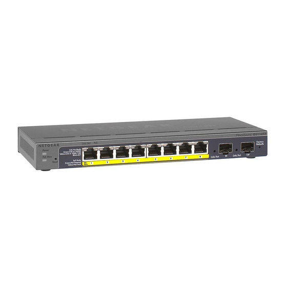
This chapter describes the NETGEAR GS110TP Smart PoE Switch hardware features. Topics include: • GS110TP Front and Back Panel Configuration • LED Designations • Device Hardware Interfaces GS110TP Front and Back Panel Configuration The GS110TP Smart PoE Switch has eight 10/100/1000 Mbps autosensing and two 1000 Mbps SFP Gigabit Ethernet switching ports. -
Page 12: Led Designations
• Power and Status LED • PoE Max LED Figure 2-2 illustrates the NETGEAR GS110TP Smart PoE Switch back panel. Figure 2-2 The back panel contains the following: • A DC input for the supplied 48V/1.25A external power adapter LED Designations Port LEDs The following table describes the RJ-45 and SFP port LED designations. -
Page 13: System Leds
The following table describes the system LED designations. Table 2-2. System LEDs Designation Power/Status LED • Solid Green = Power is supplied to the switch and the switch is operating normally. • Solid Yellow = The switch is booting. • Off = Power is disconnected. -
Page 14: Reset Button
This action is equivalent to powering the unit off and back on. The last saved configuration is loaded into the switch as it resets. To operate the Reset button, insert a device such as a paper clip into the opening to press the recessed button. The front-panel LEDs should extinguish and light again as the switch performs its Power On Self Test (POST). -
Page 15: Applications
Your NETGEAR GS110TP Smart PoE Switch is designed to provide flexibility in configuring your network connections. It can be used as a stand-alone device or with 10 Mbps, 100 Mbps, and 1000 Mbps hubs and switches. Desktop Switching The GS110TP Smart PoE Switch can be used as a desktop switch to build a small network that enables users to have 1000 Mbps access to a file server. - Page 16 GS110TP Hardware Installation Guide Applications v1.0, March 2010...
-
Page 17: Step 1: Preparing The Site
This chapter describes the installation procedures for your NETGEAR GS110TP Smart PoE Switch. Switch installation involves the following steps: Step 1: Preparing the Site Step 2: Installing the Switch Step 3: Checking the Installation Step 4: Connecting Devices to the Switch... -
Page 18: Step 2: Installing The Switch
Step 2: Installing the Switch The GS110TP Smart PoE Switch can be used on a flat surface or mounted on the wall. Installing the Switch on a Flat Surface The switch ships with four self-adhesive rubber footpads. Stick one rubber footpad on each of the four concave spaces on the bottom of the switch. -
Page 19: Step 3: Checking The Installation
Ensure all equipment is mounted properly and securely. Step 4: Connecting Devices to the Switch The following procedure describes how to connect PCs to the switch’s RJ-45 ports. The GS110TP Smart PoE Switch contains Auto Uplink technology, which allows the attaching of devices using either straight-through or crossover cables. -
Page 20: Step 5: Applying Ac Power
The GS110TP Smart PoE Switch contains software for viewing, changing, and monitoring the way it works. This management software is not required for the switch to work. The ports can be used without using the management software. However, the management software enables the setup of VLAN and Trunking features and also improves the efficiency of the switch, which results in the improvement of its overall performance as well as the performance of the network. - Page 21 GS110TP Hardware Installation Guide Note: When the device powers up, there is a default IP address already configured on the device. The default IP address is 192.168.0.239 and subnet mask 255.255.255.0. Installation v1.0, March 2010...
- Page 22 GS110TP Hardware Installation Guide Installation v1.0, March 2010...
-
Page 23: Appendix A Troubleshooting
This chapter provides information about troubleshooting the NETGEAR Smart Switch. Topics include the following: • Troubleshooting Chart • Additional Troubleshooting Suggestions Troubleshooting Chart The following table lists symptoms, causes, and solutions of possible problems. Table A-1. Troubleshooting Chart Symptom Cause Power LED is off. -
Page 24: Additional Troubleshooting Suggestions
AC power from the switch and then reapply AC power. If the problem continues, contact NETGEAR technical support. In North America, call 1-888-NETGEAR. If you are outside of North America, please refer to the support information card included with your product. -
Page 25: Auto-Negotiation
The RJ-45 ports negotiate the correct duplex mode and speed if the device at the other end of the link supports auto negotiation. If the device does not support auto negotiation, the switch only determines the speed correctly and the duplex mode defaults to half-duplex. - Page 26 GS110TP Hardware Installation Guide Troubleshooting v1.0, March 2010...
-
Page 27: Technical Specifications
Appendix B Technical Specifications Network Protocol and Standards Compatibility IEEE 802.3i 10BASE-T IEEE 802.3u 100BASE-TX IEEE 802.3ab 1000BASE-T IEEE 802.3x flow control IEEE 802.3z 1000BASE-X IEEE 802.3af DTE Power via MDI Management Windows 2000 + XP, Vista; Microsoft Explorer 6.0 or higher IEEE 802.1Q VLAN IEEE 802.3ad Link Aggregation IEEE 802.1D Spanning Tree Protocol... - Page 28 GS110TP Hardware Installation Guide Interface Eight RJ-45 connectors for 10BASE-T, 100BASE-TX, and 1000BASE-T (Auto Uplink™ on all ports) Two SFP slots for SFP modules LEDs Per RJ-45 port: Speed/Link/Activity Per SFP port: SFP indicator Performance Specifications Forwarding modes: Store-and-forward Bandwidth: 20 Gbps Address database size: 4K media access control (MAC) addresses per system Mean Time Between Failure (MTBF): 157,004 hours Power Supply...
- Page 29 GS110TP Hardware Installation Guide Electromagnetic Emissions FCC Class B CE Class B: Includes EN55022 (CISPR 22), 55024, and 50082-1 VCCI Class B C-Tick Safety UL/cUL (UL 1950)/cUL IEC950/EN60950) CE (includes EN60950) IEC950 Technical Specifications v1.0, March 2010...
- Page 30 GS110TP Hardware Installation Guide Technical Specifications v1.0, March 2010...
-
Page 31: Index
IEEE 802.3i 1-2 IEEE 802.3x 1-2 IEEE Standards 1-2 IEEE-compliant 1-2 Installation Guide 1-4 Installing the Switch 4-2 LED Designations 2-2 Low Latency 1-2 MAC 1-2 Media Access Control 1-2 Netgear Smart Control Center Utility 1-1 v1.0, March 2010 Index Index-1... - Page 32 Preparing the Site 4-1 Rack-mount Kit 1-4 Reset Button 2-1 RJ-45 1-2 RJ-45 Ports 2-2 Rubber footpads 1-4, 4-2 Site Requirements 4-1 Smart Switch Resource CD 1-4 Straight-through 2-4 System LEDs 2-3 Temperature 4-2 Traffic Control 1-1 Troubleshooting Chart A-17 User Intervention 2-4 User’s Manual 1-4...