Bosch Access Modular Controller 2 Manual
Hide thumbs
Also See for Access Modular Controller 2:
- Original instructions manual (82 pages) ,
- User manual (81 pages) ,
- Manual (56 pages)

Related Manuals for Bosch Access Modular Controller 2


Summary of Contents for Bosch Access Modular Controller 2
- Page 1 Access Modular Controller 2 ADS‑AMC2‑2WCF | APC‑AMC2‑2WCF Руководство по установке...
-
Page 3: Table Of Contents
Access Modular Controller 2 Table of contents | en Table of contents Safety Short information Introduction Description Product overview 3.2.1 Mainboard 3.2.2 Status display System overview Installing Mounting the device on a mounting rail Unmounting the device from a mounting rail... - Page 4 | Table of contents Access Modular Controller 2 11.2.1 Bootloader V00.49 11.2.2 Firmware until 6x.45, 37.60 11.2.3 Firrmware xx.61, 37.71 11.2.4 Firmware xx.62, 37.72 2022-11 | V05 | Bosch Security Systems B.V. Руководство по установке...
-
Page 5: Safety
Access Modular Controller 2 Safety | en Safety Warning! Read instructions Before working with the device, read these instructions carefully. Make sure you have understood all information described in this document. Caution! Fire hazard and risk of electric shock due to unauthorized spare parts and accessories Unauthorized spare parts and accessories might lack grounding wires or other safety elements. - Page 6 | Safety Access Modular Controller 2 Notice! Unauthorized access If this product is installed in an unprotected environment, unauthorized people may be able to enter. Install the product in a location with restricted access. This device is not suitable for use in locations where children may be present.
-
Page 7: Short Information
If you need further assistance or have any questions, contact: Bosch Security Systems B.V. Torenallee 49 5617 BA Eindhoven Netherlands www.boschsecurity.com © Bosch Security Systems B.V., 2020 Bosch Security Systems B.V. 2022-11 | V05 | Руководство по установке... -
Page 8: Introduction
| Introduction Access Modular Controller 2 Introduction Description The controller is equipped with two independent interfaces for Wiegand type readers. It is able to control one door with one reader in each direction and up to two doors with a reader in one direction only. - Page 9 The extensions offer 8 or 16 additional inputs and outputs. In the Bosch Access Host Systems, the setup procedure for a controller is made very simple and fast by the use of door templates. Once selected, all the inputs and outputs are predefined.
-
Page 10: Product Overview
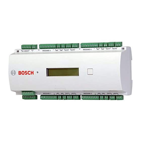
| Introduction Access Modular Controller 2 Product overview 3.2.1 Mainboard Figure 3.3: Upper circuit board with display (front) DIP switch for RS-485 address and protocol selection. Lithium battery for buffering of static RAM and real time clock (RTC). The battery life is estimated at 10 years, nevertheless an error message is generated if the voltage sinks below a preset minimum level. - Page 11 Access Modular Controller 2 Introduction | en Figure 3.4: Interfaces - overview RS-485 extension module bus External tamper contact Connector for power supply Wiegand interfaces for card readers Connectors for analog inputs Connectors for relay outputs Figure 3.5: Jumper (back) Jumper for setting either voltage free relay output (“dry” mode) or looped-in voltage from the AMC internal power supply (“wet”...
-
Page 12: Status Display
| Introduction Access Modular Controller 2 3.2.2 Status display Figure 3.6: Dialog button of the controller The liquid crystal display delivers status information about the controller. Push the dialog button to switch between different modes. The selected display mode remains set until the next time the button is pressed. -
Page 13: System Overview
Access Modular Controller 2 Introduction | en System overview The controller can be connected to the host system through one of the following interfaces, depending on the type of installation: – Ethernet – RS-485 multi-dropped, not supported by: – BIS 4.9.1 and later –... -
Page 14: Installing
| Installing Access Modular Controller 2 Installing Mounting the device on a mounting rail The controller can be attached on a standard 35 mm (1.377 in.) mounting rail using a snap-in mechanism. Attach the controller into the upper edge of the mounting rail [1], then push down the device and snap it onto the rail by pushing it towards the back [2]. -
Page 15: Unmounting The Device From A Mounting Rail
Access Modular Controller 2 Installing | en Unmounting the device from a mounting rail Notice! To remove the controller from a mounting rail, first remove all pluggable connectors. Push down the controller until the lower edge snaps out of the mounting rail [1]. Pull the lower end of the controller from the mounting rail [2]. -
Page 16: Opening The Case
| Installing Access Modular Controller 2 Opening the case Notice! To open the controller, first remove all pluggable connectors. The controller’s case consists of a top cover mounted with a two-point snap-in closure on a chassis. To open the case, push down the two snap-ins with a screwdriver, then swing the cover down. -
Page 17: Closing The Case
[1]. Please ensure that the BOSCH logo is not upside-down. The upper edge of the front cover now aligns with the two-point snap-in closures on the upper edge of the back cover [2], and may thus be clicked gently into place. -
Page 18: Cabling
| Installing Access Modular Controller 2 Cabling Notice! Risk of malfunction The cables used in the controller are not prone to electrical interference. However, you should avoid routing cables close to heavy load switching cables and equipment. If this is unavoidable, cross the cable at right angles every 1 to 2 m (3 to 6 ft) to reduce interference. -
Page 19: Grounding And Shielding
Access Modular Controller 2 Installing | en Grounding and shielding The main grounding point at the controller is connected to pin 2 of the power supply connector - see Connecting diagrams. It is good practice to shield all wires carrying low level signals. -
Page 20: Grounding For Extension Interface
| Installing Access Modular Controller 2 – no party line exists, the jumper JP2 is set (= A3) – a party line exists and signal ground is connected, the jumper JP2 is set at the first device only (= A3) –... -
Page 21: Connecting The Power Supply To The Controller
Connect an external power supply (10 VDC - 30 VDC) to the controller at pin 1 (positive) and pin 3 (0 V) of the pluggable screw connector. Bosch recommends using the Bosch APS-PSU-60 power supply unit. This power supply can also be used as an uninterpretable power supply (UPS) when using the appropriate batteries. -
Page 22: Ethernet Host Interface
When using an Ethernet connection, switches 1 and 5 of the DIP switch must be set to the ON position (= factory setting) (see Figure 3.3, item 1 , page 10 ). This also ensures correct communication with the Bosch Building Integration System (BIS) and the Bosch Access Management System (AMS). -
Page 23: Rs-485 Host Interface
Access Modular Controller 2 Installing | en RS-485 host interface The RS-485 interface is not supported by: – BIS 4.9.1 and later – AMS 4.0 and later. The RS-485 host interface of the controller can be set for using a 2- or 4-wire connection. Up to eight controllers can be used on one host bus. -
Page 24: Rs-485 Two Wire Connection
| Installing Access Modular Controller 2 Figure 4.10: RS-485 host interface 4.9.1 RS-485 Two Wire Connection Figure 4.11: Setting of the jumpers for RS-485 two wire connections 4.9.2 RS-485 Four Wire Connection Figure 4.12: Settings for RS-485 four wire connection Select the RS-485 address of the AMC2 controller using the DIP switch. - Page 25 Access Modular Controller 2 Installing | en Notice! If using an Ethernet connection, set switch 1 and 5 to ON (= delivery status). Figure 4.13: Location of the selector for host settings DIP switches Address none Table 4.1: Setting the address via the DIP switch...
-
Page 26: Rs-485 For Extension Modules
| Installing Access Modular Controller 2 Notice! Changing the type of the host connection requires a reset of the AMC2 - see Resetting the software, page 39 . 4.10 RS-485 for extension modules The RS485 Extension Module Bus expands the AMC2 with additional I/O modules (AMC2-8IOE, AMC2-16IE, AMC2-16IOE). -
Page 27: Wiegand Interface For Card Readers
Access Modular Controller 2 Installing | en 4.11 Wiegand interface for card readers The AMC2 provides two ports for connecting a maximum of 2 readers with Wiegand interfaces. Each interface is connected using a 10-pin pluggable screw - refer to Connecting diagrams. - Page 28 | Installing Access Modular Controller 2 E 1: E 2: Figure 4.18: Relay mode settings Notice! Risk of damage to equipment To prevent damage to the relays, note these specifications: - The maximum switching current is 1.25 A. - The maximum switching voltage is 30 VDC.
- Page 29 Access Modular Controller 2 Installing | en Delivery status Notice! The positions of the jumpers 1 and 2 are interchanged related to the corresponding interfaces. Bosch Security Systems B.V. 2022-11 | V05 | Руководство по установке...
-
Page 30: Connecting Analog Input Devices
| Installing Access Modular Controller 2 4.13 Connecting analog input devices The AMC2 has 4 analog inputs, for example, for potential-free lock mechanisms, or to detect whether a lock is closed or open. The inputs will be connected to the 2-pin pluggable screw connectors: S3, S4, S8 and S9 - refer to Connecting diagrams, page 45 . -
Page 31: Tamper Protection
Access Modular Controller 2 Installing | en The extension package includes 2.2 kΩ resistors which can be used to replace R and R resistors. To detect the four states, the voltage drop in the connecting cable may not exceed special values. -
Page 32: Operating
| Operating Access Modular Controller 2 Operating Configuring Ethernet interface To configure the controller in a TCP/IP network environment, use the controllers IPConfig tool of the access control system. The tool is delivered with the access host system software. -
Page 33: Ul Requirements
The enclosures AMC2-UL01 (for one device) or AMC2-UL02 (for two devices). – For every enclosure, a power supply Bosch APS-PSU-60 is necessary, and must be located in the same room as the connected AMC2 device. Recommended maximum distance between power supply unit and AMC2 is 3 m (9.84 ft). -
Page 34: System Requirements
| UL requirements Access Modular Controller 2 System requirements 6.1.1 Computer Host system For detailed information about the needed Operating system and Hardware, please refer to the corresponding installation manual of the used Management system. Notice! Computers used for UL installations must be UL listed by the Information Technology Equipment Group (ITE). - Page 35 UL requirements | en – All units are to be powered by the Bosch APS-PSU-60 power supply for UL installations. The power supply must be located in the same room as the connected AMC2 device. Recommended maximum distance between power supply unit and AMC2 is 3 m (9.84 ft).
- Page 36 | UL requirements Access Modular Controller 2 Figure 6.1: Example of mountings with extensions 2022-11 | V05 | Bosch Security Systems B.V. Руководство по установке...
-
Page 37: Extended Technical Specification
Access Modular Controller 2 UL requirements | en Position Description Position Description Black / brown Battery connection Earth cable Blue R-485 extension connection Green or green / yellow Tamper connection AC power connection Ethernet cable DC power to AMC2 Grounding points Caution! Risk of electrical interference. -
Page 38: Troubleshooting
| Troubleshooting Access Modular Controller 2 Troubleshooting If problems occur read the table below. Adjust only those controls specified in the installation manual. Improper adjustment of other controls may result in damage, and require extensive work by a qualified technician to restore the unit to normal operation. -
Page 39: Resetting The Software
Access Modular Controller 2 Troubleshooting | en Resetting the software Insert the provided screwdriver into the hole until it reaches the reset button as shown in the figure below. Press the reset button with the screwdriver. Look at the LCD display. It will indicate the word Reset. -
Page 40: Resetting The Device To Factory Default
| Troubleshooting Access Modular Controller 2 Resetting the device to factory default If connected to the Ethernet, release the connection. Open the upper case of the controller as described in Opening the Case. Reset the controller as described in Resetting the software, page 39 . -
Page 41: Service And Repair
Access Modular Controller 2 Service and repair | en Service and repair The controller is backed by a standard warranty of 3 years. Contact your dealer to buy a warranty extension. Warning! Risk of electric shock Opening or removing the covers can expose you to dangerous voltages. An electric shock can cause injuries or death. -
Page 42: Disposal
| Disposal Access Modular Controller 2 Disposal Old electrical and electronic equipment This product and/or battery must be disposed of separately from household waste. Dispose such equipment according to local laws and regulations, to allow their reuse and/or recycling. This will help in conserving resources, and in protecting human health and the environment. -
Page 43: Technical Specifications
Access Modular Controller 2 Technical specifications | en Technical specifications Mechanical Type DIN rail mounting Housing material ABS and Polycarbonate (UL94V-0) Dimensions (H × W × D) 232 mm × 90 mm × 63 mm (9.13 in. × 3.54 in. × 2.48 in.) - Page 44 | Technical specifications Access Modular Controller 2 Notice! To determine the environmental impact of an installation, take the most extreme values of all participating devices into account. Notice! To determine the vulnerability of an installation, take the most restrictive values of all participating devices into account.
-
Page 45: Appendices
Access Modular Controller 2 Appendices | en Appendices 11.1 Connecting diagrams Ethernet RJ45 RS485 Host RS232 1 2 3 4 5 6 Figure 11.1: Connectors on upper PCB The RS-485 interface is not supported by: – BIS 4.9.1 and later –... - Page 46 | Appendices Access Modular Controller 2 Figure 11.2: Interconnect diagramm of the project-specific interface Power Supply RS485-Slave-Bus Tamper Contact Reader Interface 1 Analog Input 1 Analog Input 2 Relay Output 1 AMC2 2W Relay Output 2 Reader Interface 2 Analog Input 3...
- Page 47 Access Modular Controller 2 Appendices | en Power supply, DC positive (10V - 30V) Shield Power supply (0V) UPS (power good signal) - AC UPS (power good signal) - Battery UPS (power good signal) - DC UPS (power good signal) - Common Table 11.6: Power supply...
-
Page 48: Status Display
| Appendices Access Modular Controller 2 Power supply (10V - 30V) Power supply GND Shield Data RxTx+ Data RxTx- Table 11.10: Host / Extension interface Tamper Contact, in Tamper Contact, out Table 11.11: External tamper contact 11.2 Status display 11.2.1 Bootloader V00.49... - Page 49 Access Modular Controller 2 Appendices | en 11.2.2 Firmware until 6x.45, 37.60 Push Display (Example) Description Vaa.bb 01.05.17 aa = Reader Protocol Version 37 - Wiegand, 60 - Lbus, 61 - BG900, 62 - OSDP bb = Firmware Version 01.05.17 release date of the firmware (dd.mm.yy)
- Page 50 | Appendices Access Modular Controller 2 11.2.3 Firrmware xx.61, 37.71 Push Display (Example) Description AMC-xxxxx Display firmware variants: - Bootloader - WIEGAND - LBUS - OSDP - BG900 Vxx.xx xx.xx.xx aa = Reader Protocol Version 37 - Wiegand, 60 - Lbus, 61 - BG900, 62 - OSDP bb = Firmware Version 01.05.17 release date of the firmware (dd.mm.yy)
- Page 51 Access Modular Controller 2 Appendices | en packages from the host interface. RS 485 Bus connection: A = Address 1 … H = Address 8 HSC state: x Host secure status: 1 = enable 2 = disable (Not available for Bootloader FW) 11.2.4...
- Page 52 | Appendices Access Modular Controller 2 N AMC-1234-5678 Network name of the controller (max. 14 char.) See Configuring Ethernet interface, page 32 . I 192.168.10.18 IP-address of the controller G 192.168.10.255 IP-address of the gateway M 255.255.255.0 Subnetmask H 192.168.10.10...
- Page 53 – Repair & Exchange – Product Security Bosch Building Technologies Academy Visit the Bosch Building Technologies Academy website and have access to training courses, video tutorials and documents: www.boschsecurity.com/xc/en/support/training/ Bosch Security Systems B.V. 2022-11 | V05 | Руководство по установке...
- Page 54 | Appendices Access Modular Controller 2 2022-11 | V05 | Bosch Security Systems B.V. Руководство по установке...
- Page 56 Bosch Security Systems B.V. Torenallee 49 5617 BA Eindhoven Netherlands www.boschsecurity.com © Bosch Security Systems B.V., 2022 Building solutions for a better life. 202211161145...