Motorola DCT5100 Installation Manual
Digital consumer terminal
Hide thumbs
Also See for DCT5100:
- User manual (58 pages) ,
- Setup manual (12 pages) ,
- Quick start manual (8 pages)

Related Manuals for Motorola DCT5100


Summary of Contents for Motorola DCT5100
- Page 1 D C T 5 1 0 0 D i g i t a l C o n s u m e r T e r m i n a l I n s t a l l a t i o n M a n u a l VIDEO IN L AUDIO IN R INFO...
- Page 2 These servicing instructions are for use by qualified personnel only. To reduce the risk of electrical shock, do not perform any servicing other than that contained in the Installation and Troubleshooting Instructions unless you are qualified to do so. Refer all servicing to qualified service personnel.
-
Page 3: Fcc Compliance
Any changes or modifications not expressly approved by Motorola could void the user’s authority to operate this equipment under the rules and regulations of the FCC. However, there is no guarantee that interference will not occur in a particular installation. - Page 4 Motorola, Inc. Motorola reserves the right to revise this publication and to make changes in content from time to time without obligation on the part of Motorola to provide notification of such revision or change. Motorola provides this guide without warranty of any kind, either implied or expressed, including, but not limited to, the implied warranties of merchantability and fitness for a particular purpose.
-
Page 5: Table Of Contents
RF Bypass Switch Option...2-4 Remote Controls...2-5 DRC 400 Remote Control ...2-5 Installing Batteries in the Remote Control...2-7 Section 3 Installation Installing the DCT5100 ...3-1 Standard Cabling Diagram ...3-2 RF Bypass Switch Cabling Diagrams...3-3 Audio/Video Cabling Diagrams...3-4 Audio-Only Receiver ...3-8 IR Blaster Transmitter ...3-10 Locating the IR Receiver on the VCR ...3-10... - Page 6 EMM PROVIDER ID... 4-10 d04 In-Band (IB) Diagnostic ... 4-11 MODE... 4-12 CARRIER LOCK... 4-12 DATA ... 4-12 Signal-to-Noise Ratio (SNR)... 4-13 Automatic Gain Control (AGC) ... 4-13 5 SECOND ERROR COUNTS... 4-13 d05 Unit Address... 4-14 TVPC INSTALLED... 4-14 DCT5100 Installation Manual...
- Page 7 Keypad - LED ...4-28 Front-Panel Keypad Diagnostic ...4-28 d11 INTERFACE STATUS ...4-29 INTERFACE STATUS...4-29 d12 USER SETTING STATUS ...4-30 OUTPUT TYPE...4-30 CLOSED CAPTION...4-31 PEN SIZE...4-31 FONT STYLE...4-31 FOREGROUND COLOR ...4-31 FOREGROUND OPACITY ...4-32 BACKGROUND COLOR ...4-32 Contents DCT5100 Installation Manual...
- Page 8 IP ADDRESS ... 4-34 UPM ... 4-35 UPSTREAM ID... 4-35 DOWNSTREAM ID ... 4-35 STATE... 4-35 MAC ABORT COUNTER... 4-36 SOCKET PORT STATE... 4-36 Section 5 Troubleshooting Appendix A Specifications and Features Specifications...A-1 Features List...A-2 Abbreviations and Acronyms DCT5100 Installation Manual...
- Page 9 Contents Figures Figure 1-1 DCT5100 set-top terminal...1-2 Figure 2-1 Front panel...2-1 Figure 2-2 DCT5100 rear panel...2-3 Figure 2-3 RF Bypass switch option ...2-4 Figure 2-4 DRC 400 remote control ...2-5 Figure 3-1 Standard VCR cabling...3-2 Figure 3-2 RF Bypass switch...3-3 Figure 3-3 Audio system cabling ...3-5...
- Page 10 Table 4-26 PREVIEW mode indicators – OSD and LED ... 4-20 Table 4-27 MPEG VIDEO LOCK ... 4-20 Table 4-28 MPEG AUDIO LOCK values... 4-21 Table 4-29 PCR LOCK values ... 4-21 Table 4-30 RF upstream modem... 4-22 Table 4-31 CODE MODULES - OSD ... 4-24 DCT5100 Installation Manual...
- Page 11 Contents Table 4-32 Object STATUS ...4-26 Table 4-33 MEMORY CONFIGURATION - OSD ...4-27 Table 4-34 INTERFACE STATUS ...4-29 Table 4-35 USER SETTING STATUS – OSD ...4-30 Table 4-36 INTERACTIVE INFO - OSD ...4-34 DCT5100 Installation Manual...
- Page 12 Enables secure electronic commerce transactions Downloads and executes service applications The DCT5100 is a feature rich hardware platform that is one part of Motorola’s end-to-end system solutions. It requires the appropriate operating system software applications, transmission equipment, and control equipment to function properly and seamlessly.
-
Page 13: Standard Features
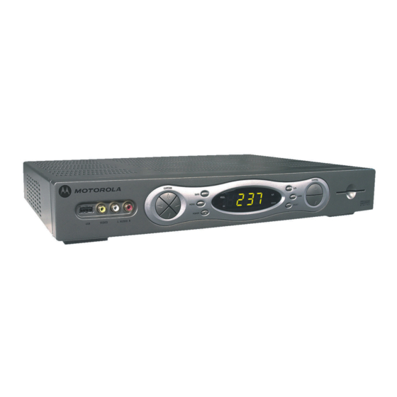
Introduction Figure 1-1 illustrates front and rear views of the DCT5100: Figure 1-1 DCT5100 set-top terminal VIDEO IN L AUDIO I N R TV/VCR CABLE Standard Features The Motorola DCT5100 offers the following standard features: Two tuners up to 860 MHz... -
Page 14: Optional Features
Macrovision copy protection 4 digit, 7 segment LED display Full feature access from front panel Optional Features RF Bypass switch Expansion DRAM Expansion FLASH 1394 “Firewire” digital interface (dual connector interface) IR Blaster transmitter HPNA 2.0 (RJ-11) Interface DCT5100 Installation Manual... -
Page 15: Features List
Introduction provides a product description, a list of related documentation, the technical helpline telephone number, and the repair/return procedure. Section 2 Overview describes the DCT5100 terminal and provides an overview of its use. This section also identifies the front-panel displays and switches and describes the rear-panel features. -
Page 16: If You Need Help
24 hours per day, 7 days per week. Calling for Repairs If repair is necessary, call the Motorola Repair Facility at 1-800-227-0450 for a Return for Service Authorization (RSA) number before sending the unit. The RSA number must be prominently displayed on all equipment cartons. -
Page 17: Overview
Ethernet connection on the back panel without interrupting TV viewing. Front Panel The controls on the front panel provide functional navigation of the DCT5100 if the remote control is lost or is temporarily out of service. Certain functions, such as those requiring a numeric entry, are not available without a remote control. -
Page 18: Table 2-1 Front Panel
Displays the channel number or time of day. There are four indicator lights on the LED screen: MSGS. — the DCT5100 has received messages for you to read ON — the DCT5100 is powered on A/B — the RF bypass is active REMOTE —... -
Page 19: Rear Panel
Rear Panel Figure 2-2 illustrates the rear panel of the DCT5100, which contains a switched power outlet; connectors for video, audio, and RF cabling; data output; and modem and data interface connectors. Figure 2-2 DCT5100 rear panel TV/VCR CABLE Table 2-2 describes the rear-panel connections:... -
Page 20: Rf Bypass Switch Option
The RF Bypass causes the cable signal to pass the DCT5100 and go directly to a TV or VCR. Figure 2-3 illustrates the RF Bypass switch option:... -
Page 21: Remote Controls
Remote Controls The basic DCT5100 uses the DRC 400 remote control. If your system offers an optional Interactive Program Guide (IPG), you may need a different remote control. Before using the DCT5100, refer to the remote control user instructions to program the remote control. - Page 22 LAST CHANNEL + or - FAVORITE ENTER/MUSIC DCT5100 Installation Manual Description Moves the cursor around the program guide and menu screens. Selects menu options such as pay-per-view events or tuning programs from the program guide. (The OK key performs the same functions.)
-
Page 23: Installing Batteries In The Remote Control
To install batteries in an DRC 400: Press the battery-compartment cover and slide off. Insert two new batteries in the direction indicated on the inside of the battery compartment. Slide the battery compartment cover back into place. Overview DCT5100 Installation Manual... -
Page 24: Installation
Locate the cabling diagram that matches the subscriber’s configuration requirement. Connect the cables as illustrated in that diagram. Determine if you are connecting the DCT5100 to a data device (see “Data Devices” in this section). For installation details, refer to instructions included with the data device being installed. -
Page 25: Standard Cabling Diagram
RF cabling diagram that enables you to record on your VCR the currently tuned channel. When a VCR is not present, connect the coax cable from the DCT5100 directly to the CABLE IN connector on the TV. The output from the RF connection will be on channel 3 or 4, depending on the configuration information coming from the control system. -
Page 26: Rf Bypass Switch Cabling Diagrams
DCT5100. The bypass mode is automatically initiated under one of three conditions: when the DCT5100 loses power, when it is turned off from the front panel, or when the user manually activates the switch by pressing the A/B key. If the DCT5100 loses power or is turned off, the subscriber can continue viewing the clear analog channels on the cable system. -
Page 27: Audio/Video Cabling Diagrams
Installation Audio/Video Cabling Diagrams The DCT5100 is capable of delivering Dolby AC-3 audio to a Dolby Digital stereo receiver using the SPDIF RCA connector. When connecting to a receiver, you can use the left/right RCA baseband audio outputs or the SPDIF RCA connection. The connections you use will depend on the capabilities of the audio receiver. -
Page 28: Figure 3-3 Audio System Cabling
TV to the monitor output so On-Screen menus associated with the receiver can be displayed. (In many cases the receivers themselves have interactive on-screen menus). Figure 3-3 illustrates the DCT5100 interfacing directly to a digital receiver: Figure 3-3... -
Page 29: Figure 3-4 Video System Cabling
Installation Figure 3-4 illustrates how to connect video outputs of the DCT5100: Figure 3-4 Video System Cabling ETHERNET TV/VCR CABLE MONITOR S-VIDEO VIDEO RIGHT LEFT either/or Stereo TV CABLE/ ANTENNA IN When connecting the video path, never connect both baseband composite video and S-Video together. -
Page 30: Figure 3-5 Hdtv Cabling
Figure 3-5 HDTV Cabling TV/VCR CABLE Component Video Input CABLE/ ANTENNA IN AUDIO IN VIDEO SPDIF ETHERNET HPNA S-VIDEO Pass Card AUDIO Installation DCT 5100 IEEE 1394 SWITCHED 105-125V 60Hz CONVENIENCE 4A MAX OUTLET 500W MAX OPTICAL SPDIF DCT5100 Installation Manual... -
Page 31: Audio-Only Receiver
Installation Audio-Only Receiver When connecting to an audio-only receiver, such as a home mini system, follow a daisy-chain convention. Figure 3-6 illustrates how the audio and video paths flow through each device in a daisy-chain fashion: Figure 3-6 Audio-only receiver... -
Page 32: Figure 3-7 Audio With Stereo Last
ANTENNA IN AUDIO VIDEO S-VIDEO AUDIO VIDEO S-VIDEO To TV Stereo receiver INPUT AUDIO VIDEO S-VIDEO CABLE Installation IEEE 1394 SWITCHED 105-125V 60Hz CONVENIENCE 4A MAX OUTLET 500W MAX either/or OUTPUT DIGITAL AUDIO VIDEO S-VIDEO COAXIAL OPTICAL DCT5100 Installation Manual... -
Page 33: Ir Blaster Transmitter
IR Blaster near the VCR IR receiver. A mini-pin connector at the end of the cord connects the IR Blaster to the DCT5100. The IR Blaster is sold separately as an accessory item. The availability and functionality of the IR Blaster depends on the installed application software. -
Page 34: Installing The Ir Blaster
The IR Blaster is now located near the receiver and the VCR can be controlled through the DCT5100. As a final check, operate the VCR using the remote control from various positions in the room. If the IR Blaster is obstructing the IR receiver on the VCR, move it slightly. -
Page 35: Data Devices
The functionality of each data device port requires, and depends on, installed application software. Rear Panel Connections The DCT5100 rear panel includes a USB port and an Ethernet network interface. The following optional connections are also available: HPNA RJ-11 interface... -
Page 36: Usb
Front Panel Connections The DCT5100 front panel includes a SmartCard interface and an additional USB port. Smart Card Interface The DCT5100 is equipped with an ISO 7816 SmartCard interface. This device is intended for Electronic Commerce use. Additional USB Port The USB port is used to daisy-chain USB equipped devices such as printers and storage devices. -
Page 37: Boot Cycle
3-14 Installation Boot Cycle After connecting the proper cabling to the DCT5100, plug the power cord into the DCT5100 and electrical wall outlet. Begin performing the boot cycle procedure: The LED displays HUNT and then FR 1. The DCT5100 begins searching for the headend Out of Band (OOB) frequency carrier. If the OOB frequency is not set to 75.25 MHz, the LED flashes FR 1 and then flashes FR 2. -
Page 38: Boot Cycle Error Codes
FP for up to 60 seconds during flash programming. The DCT5100 is ready for initialization by the headend controller when the LED display is blank. Verify that the DCT5100 is powered up or reset within two minutes of a completed download. - Page 39 DCT5100 Installation Manual When error occurs Reset within two minutes of a complete software object download After plugging the DCT5100 into an electrical outlet to begin the boot cycle After cycling twice through the OOB frequencies (LED then displays Eb 02...
-
Page 40: Operational Check
Testing Procedure Press Power on POWER Tune to the output channel of the DCT5100 (channel 3 or 4). Scan through the channels using the Channel Selection Tune to several channels by entering the channel number using the numeric keys. Press... -
Page 41: Diagnostics
All sample displays are illustrative; actual data may differ from the examples. Accessing Diagnostics You can run the base platform software or Thin Client software to access the DCT5100 diagnostics. The Heritage mode and the Enhanced mode are the two modes of entry for accessing diagnostics. -
Page 42: Figure 4-1 Main Menu Diagnostic - Led
Diagnostics Table 4-1 illustrates the OSD of the diagnostic main menu. Note, d13 INTERACTIVE INFO will only be displayed when Thin Client is running in the DCT5100. Table 4-1 Main menu - OSD DIAGNOSTICS GENERAL STATUS PURCHASE STATUS OOB STATUS... -
Page 43: D01 General Status
MODEL ID: REMOD CHANNEL: SETTOP TIME: Figure 4-2 is an example of a GENERAL STATUS diagnostic LED: Figure 4-2 General status - LED E 00 DISCONNECTED 0256 0000 0087 xxxxxxxxxx GPS MUTE MUTE Environment Error code code Diagnostics DCT5100 Installation Manual... -
Page 44: Error Codes
Client) Error codes ranging from 00 to 17 to remain consistent with digital set-tops prior to the DCT5100. Error code EP18 applies to the DCT5100 only. Table 4-3 lists the different types of hardware errors, and the corresponding error code... -
Page 45: Remod Channel
The REMOD CHANNEL number can be either 3 or 4 (USA systems). The output port configuration displays the configuration of the DCT5100 output or re-modulated (remod) port. The output port/remod port is the interface from the DCT5100 to the subscriber’s television set. SETTOP TIME The SETTOP TIME is current OOB set-top time displayed in Global Positioning System (GPS) seconds from Jan 6, 1980. -
Page 46: Unsent Purchases
IPPV status is enabled. Table 4-5 lists the IPPV Status indicators for OSD and LED: Table 4-5 IPPV status indicators – OSD and LED OSD Display LED Indicator ENABLED DISABLED DCT5100 Installation Manual Definition IPPV Enabled IPPV Disabled... -
Page 47: D03 Out-Of-Band (Oob) Diagnostic
Table 4-6 illustrates the OOB status on the OSD: Table 4-6 OOB status - OSD OOB DIAGNOSTIC OOB FREQUENCY: CARRIER LOCK: DATA: EMM DATA: SNR: AGC: NETWORK PID: EMM PID: EMM PROVIDER ID: 075.25 22.1 dB GOOD 23 % FAIR 100C 1003 100A Diagnostics DCT5100 Installation Manual... -
Page 48: Oob Frequency
The OOB FREQUENCY is the center frequency of the set-top OOB tuner. The frequency range is 70 to 130 MHz. OOB CARRIER LOCK The OOB CARRIER LOCK indicates if the OOB receiver is locked to the carrier. Table 4-7 illustrates valid carrier lock indicators: Table 4-7 CARRIER LOCK indicators –... -
Page 49: Oob Data
This field is only valid when carrier lock has been established. Definition OOB data detected within last 5 seconds OOB data not detected within last 5 seconds Definition EMM data detected within last 5 seconds EMM data not detected within last 5 seconds Diagnostics DCT5100 Installation Manual... -
Page 50: Oob Automatic Gain Control (Agc)
AGC value not valid This field is valid only when carrier lock has been established. NETWORK PID The DCT5100 is tuned to the NETWORK PID to receive network messages. This value is displayed in hexadecimal format. EMM PID The EMM PID is the PID stream the set-top tunes to for EMM data. This value is displayed in hexadecimal format. -
Page 51: D04 In-Band (Ib) Diagnostic
In-Band (IB) Diagnostic The DCT5100 displays the IN-BAND DIAGNOSTIC status of a digital carrier for the last attempted tuned channel. If a digital carrier is not present, this diagnostic indicates the carrier is not locked. Table 4-12 illustrates the OSD of the IB receiver digital status:... -
Page 52: Mode
Contains a Digital channel with a modulation mode of 256 QAM CARRIER LOCK The IB CARRIER LOCK indicates if the IB receiver is locked to the carrier. Table 5-15 illustrates valid values displayed on the LED and OSD: Table 4-14... -
Page 53: Signal-To-Noise Ratio (Snr)
The count is shown in decimal format and the maximum value is 9999. The maximum value displayed is 9999 even if the number of errors exceeds 9999. Diagnostics 4-13 DCT5100 Installation Manual... -
Page 54: D05 Unit Address
4-14 Diagnostics d05 Unit Address The UNIT ADDRESS diagnostic displays the unit address of the DCT5100. Table 4-18 illustrates a unit address on OSD: Table 4-18 UNIT ADDRESS - OSD UNIT ADDRESS TVPC INSTALLED UNIT ADDRESS: 123-45678-90123-456 NETWORK ADDRESS: 123-45678-90123-456 OOB MULTICAST 16 ADDRESS FOR: MAC Address 1–... -
Page 55: Unit Address
UNIT ADDRESS The UNIT ADDRESS identifier indicates the unit address or physical address of the DCT5100 set-top terminal. The UNIT ADDRESS is unique and displayed in decimal format. Figure 4-6 illustrates the LED display of a unit address: Figure 4-6... -
Page 56: Oob Multicast 16 Address
Messages not matching the multicast address are discarded. MAC ADDRESS The MAC addresses are stored in Protected Flash and displayed in hexadecimal format. MAC addresses are assigned to the DOCSIS, Ethernet, 1394, USB, and set-top. DCT5100 Installation Manual... -
Page 57: D06 Current Channel Status
Table 4-21 illustrates the digital CURRENT CHANNEL STATUS OSD: Table 4-21 Digital CURRENT CHANNEL STATUS - OSD CURRENT CHANNEL STATUS TYPE: INBAND FREQUENCY: AUTHORIZED: PURCHASABLE: PURCHASED: PREVIEW: MPEG VIDEO LOCK MPEG AUDIO LOCK PCR LOCK Diagnostics ANALOG 077.2500 MHz DIGITAL 0xbb 199.2500 MHz DCT5100 Installation Manual 4-17... -
Page 58: Type
LED displays for analog and digital channels. Table 4-22 lists the display information: Table 4-22 Current channel TYPE – OSD and LED OSD Display LED Display ANALOG DIGITAL DCT5100 Installation Manual Preview Purchasable indicator indicator MUTE MUTE Analog channel diagnostic... -
Page 59: Authorization Reason Code
The AUTHORIZED diagnostic displays a parameter indicating if the set-top is authorized for the currently tuned service. Table 4-24 is a list of valid authorized values: Table 4-24 AUTHORIZED values Values Description Current channel is authorized Current channel is not authorized Diagnostics 4-19 DCT5100 Installation Manual... -
Page 60: Purchasable
MPEG VIDEO LOCK Values Definition Video Processor is locked to the video stream Video Processor is not locked to the video stream DCT5100 Installation Manual Definition Current channel is purchasable. Current channel is not purchasable. Definition Channel is in preview... -
Page 61: Mpeg Audio Lock
Audio Processor is locked to the audio stream Audio Processor is not locked to the audio stream PCR LOCK The PCR LOCK indicates if the in-band receiver is locked to the current program clock reference. Valid PCR lock values are illustrated in Table 4-29:... -
Page 62: D07 Rf Modem (Upstream)
4-22 Diagnostics d07 RF MODEM (Upstream) The RF MODEM diagnostic displays the appropriate modem information based on the module installed in the DCT5100. Table 4-30 illustrates the status of the RF upstream modem: Table 4-30 RF upstream modem RF MODEM... -
Page 63: Rf Modem Status
REPORTBACK ADDRESS The REPORTBACK ADDRESS is displayed if configured. The reportback address is displayed in 4-byte hexadecimal format. LAST RB ATTEMPT TIME The last attempted reportback made by the set-top is displayed here in GPS seconds. DCT5100 Installation Manual... -
Page 64: D08 Code Modules
The CODE MODULES section includes information about the firmware loaded into flash memory and all versions of non-volatile code that are installed in the DCT5100. When the Native Suite is running, the diagnostics of the application operating system and all associated objects should be accessible. -
Page 65: Figure 4-9 Code Modules - Led
Code or SYS for the System Object) Code module version number Diagnostics Download Download data status received indicator MUTE MUTE MUTE MUTE MUTE MUTE MUTE MUTE Alternating with MUTE MUTE Indicator to separate major and minor revision numbers DCT5100 Installation Manual 4-25... -
Page 66: Bootloader
Enabled_Not_Runnable STOPPING Disabling DISABLED Disabled DIS-NOT RUN Disabled_Not_Runnable DCT5100 Installation Manual Description Memory for object has been allocated. Object is currently being loaded. Object is in the process of being started (the constructor is running). Object is running. Object has been enabled, but it is not runnable. -
Page 67: Segs / Time
NVRAM is displayed in KB. Diagnostics Description Object is in the process of being deleted. Object is not runnable in the current system; will be enabled on next boot. Connected to download PID awaiting data. Trying to connect. DCT5100 Installation Manual 4-27... -
Page 68: D10 Keypad - Led
The OSD displays characters in the format shown in Figure 4-10: Figure 4-10 Character format display - OSD < > Î A character on the OSD is highlighted when the corresponding front-panel key is depressed. DCT5100 Installation Manual... -
Page 69: D11 Interface Status
DOCSIS TUNER & XMITTER 1394 I/O DEVICE USB I/O DEVICE 10bT ETHERNET DEVICE PARALLEL PORT IR TRANSMITTER HARD DRIVE SMART CARD Diagnostics INST NOT INST NOT INST NOT INST NOT INST NOT INST NOT INST NOT INST DCT5100 Installation Manual 4-29... -
Page 70: D12 User Setting Status
When high definition output modes (1080I, 720P, or 480P) are selected, graphic overlays such as electronic program guides can only be viewed on the component video outputs. The baseband video output will continue to transmit baseband video (480I), but without graphic overlays. DCT5100 Installation Manual 1080I ENABLED... -
Page 71: Closed Caption
Displays the FOREGROUND COLOR option selected by the user: OSD Display Definition AUTO Foreground Color is controlled by the Closed Caption stream. WHITE White Foreground. BLACK Black Foreground. Red Foreground. GREEN Green Foreground. BLUE Blue Foreground. YELLOW Yellow Foreground. Diagnostics 4-31 DCT5100 Installation Manual... -
Page 72: Foreground Opacity
Displays the BACKGROUND OPACITY option selected by the user: OSD Display Definition AUTO Background Color is controlled by the Closed Caption stream. TRANSPARENT Transparent Background Opacity. TRANSLUCENT Translucent Background Opacity. SOLID Solid Background Opacity. FLASHING Flashing Background Opacity. DCT5100 Installation Manual... -
Page 73: Service Selection
Displays the ASPECT RATIO conversion mode selected by the user. The aspect ratio conversion mode is the width-to-height ratio of your screen. OSD Display Definition LETTERBOX Letterbox PAN-SCAN Pan and Scan CROPPED Cropped, fixed Pan and Scan. Diagnostics 4-33 DCT5100 Installation Manual... -
Page 74: D13 Interactive Info
The IP ADDRESS for the set-top is assigned by the NC 1500. It is displayed as four decimal fields delimited by periods, for example, xxx.xxx.xxx.xxx where each xxx ranges from 000 to 255. 0.0.0.0 is displayed when the IP address is not configured or unknown. DCT5100 Installation Manual 0.0.0.0 00000021... - Page 75 Set-top interactive state is running, sending idle messages, and waiting for any Prepare for Poll or MAC messages. Set-top interactive run state has stopped and set-top is waiting for status or transmission control message. Set-top interactive state is unknown or invalid. 4-35 DCT5100 Installation Manual...
- Page 76 READY The socket is ready to send or receive. RECEIVING The socket is receiving data from the application server. SENDING The socket is sending data to the application server. UNKNOWN The socket state is invalid or unknown. DCT5100 Installation Manual...
-
Page 77: Troubleshooting
Possible Solution Check for an obstruction between the remote control and the DCT5100. Aim the remote control directly at the DCT5100, not the TV or VCR. Press and release operation keys one at a time, firmly and deliberately. Try changing channels using the buttons on the front panel. -
Page 78: Specifications And Features
–15 dBmV through +5 dBmV Standard: security screws, unichassis construction 15 through 40 C (32 through 104 F) 5% through 95% (noncondensing) 105 through 125, 60 Hz 40 W at 115 Vac 17.13 in. 12.75 in. 2.75 in. 9.5 pounds DCT5100 Installation Manual... -
Page 79: Features List
Audio line-in/loop-through Video input (2) Smart Card reader S-Video output Audio SPDIF output (optical and coaxial) IR Blaster port Renewable security slot IEEE 1394 port Component video (Y Pb Pr) DCT5100 Installation Manual Standard Option • • • • • •... -
Page 80: Abbreviations And Acronyms
Packet identifier Pay-Per-View Quadrature amplitude modulation QPSK Quadrature phase shift keying Return for Service Authorization Signal-to-noise ratio SPDIF Sony Philips Digital Interface Format TCP/IP Transmission Control Protocol/Internet Protocol Technical Response Center TvPC TV PassCard Video on Demand DCT5100 Installation Manual...