Advertisement
Available languages
Available languages
Quick Links
Before you begin - Read these instructions completely
and carefully. IMPORTANT – OBSERVE ALL
GOVERNING CODES AND ORDINANCES. Note to
Installer – Be sure to leave these instructions with the
Consumer. Note to Consumer – Keep these instructions
with your Owner's Manual for future reference.
Tools Needed
• 5/16" nut driver
• Pliers
• Slotted screwdriver
Parts included in bag with Sub-
Base Switch Kit
Wire Nuts (4)
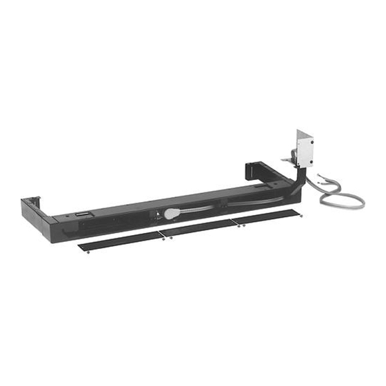
Installation Instructions
for your new
RAK204
Sub-Base Switch Kit
Sub-Base
Switch
5/16" Nut
Important Notes
• This unit must be properly grounded.
• Read this instruction before installing the sub-base to the
molded or metal case.
The sub-base should be assembled to the case before
securing the case in the wall.
CAUTION
Electrical power must be disconnected
before installing the sub-base.
Electrical Requirements :
1. Electrical wiring may enter the sub-base through any of
the knockout holes provided in the sub-base bottom or
rear. Use appropriate protection around the opening to
ensure the wiring will not become cut or chafed.
2. Refer to the unit nameplate for branch circuit
requirements.
3. All wiring should be done in accordance with the local
electrical codes and regulations.
4. Not approved for aluminum wire application.
5. If electrical wiring is placed in or against the sub-base
enclosure, the sub-base must be grounded. Use the
installed ground screw to connect the ground wire eyelet
from the kit to the rear of the sub-base.
See step 4.
RAK204SW kit compatible with the following Sub base models
Kit Number
Description
RAK204E15C
265 V
RAK204E20C
265 V
RAK204E30C
265 V
RAK204D15C
230/208 V
RAK204D20C
230/208 V
RAK204D30C
230/208 V
31-5000558 Rev. 0 10-20 GEA
15 A
20 A
30 A
15 A
20 A
30 A
Advertisement

Related Manuals for GE RAK204


Summary of Contents for GE RAK204
- Page 1 Installation Instructions for your new RAK204 Sub-Base Switch Kit Before you begin - Read these instructions completely and carefully. IMPORTANT – OBSERVE ALL GOVERNING CODES AND ORDINANCES. Note to Installer – Be sure to leave these instructions with the Consumer. Note to Consumer – Keep these instructions with your Owner’s Manual for future reference.
-
Page 2: Installation Instructions
Installation Instructions STEP 1 Screws • Disconnect all power to the unit. • Remove the three panels from the front of the sub base by removing the 5/16” screws. • Retain the middle and right hand side panels and all of the screws. STEP 2 Ground Wire To Receptacle Outlet... - Page 3 Installation Instructions STEP 3 Ground Wire To Receptacle Outlet To Power Source • Secure the Left side cover with switch assembly to the Sub Base using the retained screws. STEP 4 Existing ground wire Green ground screw (type C) • To attach the ground wire from the Sub Base Switch, place the ring terminal onto the existing ground screw and secure with the provided 5/16”...
-
Page 4: Wiring Diagram
• Use wire nuts (provided) to connect the Sub base switch to the electrical sub base wiring. See diagram above. STEP 6 • Reattach the middle and right side face plates using the screws saved from step 1. STEP 7 • Verify wiring and restore power to unit. A Quality Product of GE Appliances... - Page 5 Instructions d’installation pour votre nouveau socle RAK204SW Trousse d’interrupteur Avant de commencer – Lisez ces instructions attentivement et en totalité. de socle IMPORTANT – OBSERVEZ TOUS LES CODES ET RÈGLEMENTS EN VIGUEUR. Remarque à l’installateur – Assurez-vous de remettre ces instructions au consommateur.
-
Page 6: Instructions D'installation
Instructions d’installation ÉTAPE 1 • Débranchez toute source d’alimentation de l’appareil. • Retirez les trois panneaux de l’avant du socle en retirant les vis de 5/16 po. • Conservez les panneaux central et droit, et toutes les vis. ÉTAPE 2 Fil de mise à... - Page 7 Instructions d’installation ÉTAPE 3 Fil de mise à la terre À la prise À la source d’alimentation • Fixez le couvercle gauche avec l’interrupteur sur le socle à l’aide des vis conservées. ÉTAPE 4 Fil de mise à la terre existant Vis de mise à...
-
Page 8: Schéma De Principe
électrique. Consultez le schéma ci-dessus. ÉTAPE 6 • Fixez de nouveau les plaques frontales centrale et droite à l’aide des vis conservées à l’étape 1. ÉTAPE 7 • Vérifiez le câblage et remettez l’alimentation de l’appareil. Un produit de qualité de GE Appliances...