GE MULTILINK ML2400 Instruction Manual
Ethernet communications switch
Hide thumbs
Also See for MULTILINK ML2400:
- Quick start manual (70 pages) ,
- Quick start manual (62 pages)
Table of Contents
Advertisement
GE Consumer & Industrial
Multilin
GE Multilin
215 Anderson Avenue, Markham, Ontario
Canada L6E 1B3
Tel: (905) 294-6222 Fax: (905) 201-2098
Internet:
http://www.GEmultilin.com
*1601-0220-AB*
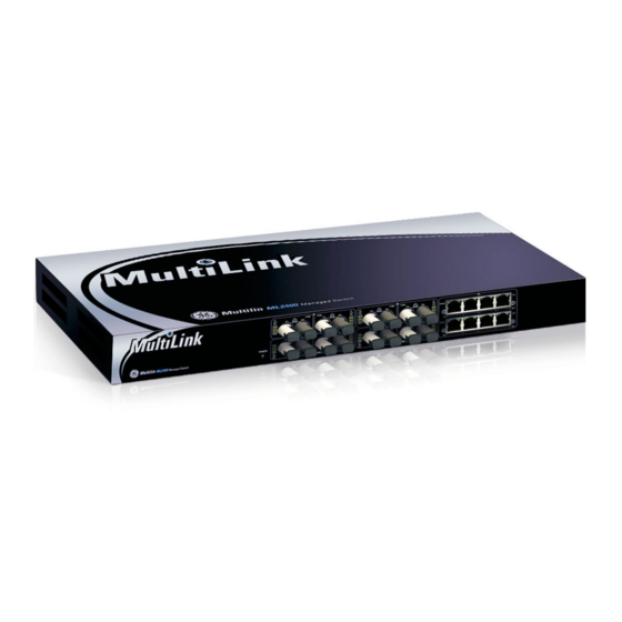
MultiLink ML2400
Ethernet Communications Switch
Instruction Manual
Firmware Revision 3.x
Manual P/N: 1601-0220-AB
Manual Order Code: GEK-113042K
Copyright © 2008 GE Multilin
I I SO9001:2000
GE Multilin's Quality
Management System is
registered to ISO9001:2000
QMI # 005094
UL # A3775
Advertisement
Table of Contents

Related Manuals for GE MULTILINK ML2400


Summary of Contents for GE MULTILINK ML2400
-
Page 1: Instruction Manual
MultiLink ML2400 Ethernet Communications Switch Instruction Manual Firmware Revision 3.x Manual P/N: 1601-0220-AB Manual Order Code: GEK-113042K Copyright © 2008 GE Multilin I I SO9001:2000 GE Multilin's Quality Management System is registered to ISO9001:2000 QMI # 005094 UL # A3775... - Page 2 The contents of this manual are the property of GE Multilin Inc. This documentation is furnished on license and may not be reproduced in whole or in part without the permission of GE Multilin. The content of this manual is for informational use only and is subject to change without notice.
-
Page 3: Table Of Contents
COMMAND LINE INTERFACE FIRMWARE ...1-10 ENERVISTA SECURE WEB MANAGEMENT ...1-18 ML2400 FIRMWARE UPDATES ...1-24 2: PRODUCT OVERVIEW ...2-1 DESCRIPTION COMMUNICATIONS MODULES ...2-3 FEATURES AND BENEFITS ...2-7 MULTILINK ML2400 ETHERNET COMMUNICATIONS SWITCH – INSTRUCTION MANUAL NSPECTING THE ACKAGE AND RODUCT ...1-2 RDER ODES ...1-3... - Page 4 ...5-3 AND BOOTP ...5-3 BOOTP ATABASE DHCP/ /AUTO ...5-3 ONFIGURING BOOTP ANUAL ...5-5 SING ELNET MULTILINK ML2400 ETHERNET COMMUNICATIONS SWITCH – INSTRUCTION MANUAL ...2-10 ) ...3-3 LOCK ) ...3-4 ...3-4 ...3-5 ...3-8 NITS ) ...4-2 ) ...4-2 OPPER ORTS ...4-5...
- Page 5 CONFIGURING 802.1X THROUGH THE COMMAND LINE INTERFACE ...7-4 CONFIGURING 802.1X WITH ENERVISTA SECURE WEB MANAGEMENT 8: ACCESS USING INTRODUCTION TO TACACS+ ...8-1 TACACS+ CONFIGURING TACACS+ THROUGH THE COMMAND LINE INTERFACE ...8-4 MULTILINK ML2400 ETHERNET COMMUNICATIONS SWITCH – INSTRUCTION MANUAL ...5-8 ETTING ERIAL ARAMETERS ...5-8...
- Page 6 ESCRIPTION ...10-13 OMMANDS ...10-14 XAMPLE SOFTWARE ...10-20 ...10-20 ESCRIPTION ...11-1 ESCRIPTION GVRP C ...11-1 ONCEPTS GVRP O ...11-2 PERATIONS ...11-7 OMMANDS GVRP O ...11-7 PERATION OTES SOFTWARE ...11-9 ...11-9 XAMPLE ...12-1 ESCRIPTION MULTILINK ML2400 ETHERNET COMMUNICATIONS SWITCH – INSTRUCTION MANUAL...
- Page 7 CONFIGURING IGMP WITH ENERVISTA SECURE WEB MANAGEMENT 16: SNMP OVERVIEW ...16-1 CONFIGURING SNMP THROUGH THE COMMAND LINE INTERFACE ...16-4 CONFIGURING SNMP WITH ENERVISTA SECURE WEB MANAGEMENT MULTILINK ML2400 ETHERNET COMMUNICATIONS SWITCH – INSTRUCTION MANUAL ...12-1 EATURES AND PERATION ...13-1 ESCRIPTION RSTP C ...13-1...
- Page 8 ODBUS EMORY ...18-36 ORMAT ODES ...19-1 HANGE OTES ...19-2 HANGES TO THE ANUAL GE M ...19-5 ULTILIN ARRANTY TATEMENT MULTILINK ML2400 ETHERNET COMMUNICATIONS SWITCH – INSTRUCTION MANUAL ...17-2 OMMAND NTERFACE ISTA ECURE ANAGEMENT ECURE ANAGEMENT ...17-13 ...17-13 ANAGEMENT OFTWARE ...17-14...
-
Page 9: Inspecting The Package And Product
Remove the items from the shipping container. Be sure to keep the shipping container should you need to re-ship the unit at a later date. To validate the product warranty, please complete and return the enclosed product registration card to GE Multilin as soon as possible. -
Page 10: Ordering
1.2.1 Order Codes The following table illustrates the order codes for the MultiLink ML2400 Ethernet Switch. The fiber optic LC ports are limited to a total of 12. ML2400 – * – * – * – * – * – * – *... -
Page 11: Specifications
Fiber port, SC-type (snap-in): ...fiber multi-mode, 100Base-FX Fiber port, ST-type (twist-lock): ...fiber multi-mode, 100Base-FX Fiber port, 1000Base-FX:...GBIC modules MULTILINK ML2400 ETHERNET COMMUNICATIONS SWITCH – INSTRUCTION MANUAL INTRODUCTION control, non-blocking 15 μs + packet time (10 to 10 Mbps and 10 to 100 Mbps) - Page 12 Internal Fuse:... HI: Ceramic, axial SLO BLO, 3 A /350 V AC PER-PORT JUMPERS AND SWITCHES The copper daughter board has on internal switch for selecting MDI-MDIX crossover on port # 1. Other port-specific user settings (such as FDX or HDX, copper 10/100 speed) can be fixed using firmware commands.
-
Page 13: Environmental Specifications
Voltage dips and Interrupts for DC power ports Conducted & Radiated Emissions Conducted & Radiated Emissions MULTILINK ML2400 ETHERNET COMMUNICATIONS SWITCH – INSTRUCTION MANUAL 2-2 for 16 hours Nominal ≤ 50°C Standard Number:Date code EN/IEC61000-4-2:1995 8Kv contact,15Kv Air (Level 4) IEEE C37.90.3:2001... -
Page 14: Physical Specifications
C22.2 No. 60950-1 IEEE 1613:2003 2000V (2000VAC & 500VAC) IEEE 1613:2003 5000V 4.32 cm × 43.2 cm × 22.9 cm (H × W × D) substations MULTILINK ML2400 ETHERNET COMMUNICATIONS SWITCH – INSTRUCTION MANUAL CHAPTER 1: INTRODUCTION Severity levels Tested... - Page 15 CSA:...Certified per C22.1 No. 60950-1 1 WARRANTY 24 months from date of shipment Manufactured in USA GE Multilin reserves the right to change specifications, performance, characteristics, and/or model offerings without notice. MULTILINK ML2400 ETHERNET COMMUNICATIONS SWITCH – INSTRUCTION MANUAL INTRODUCTION...
-
Page 16: Firmware Overview
The documentation reflects features of MultiLink Switch Software version 1.7.x or later. If your switch is not at the current version, GE Multilin recommends upgrade to version 1.7.x or later. Please refer to the GE Multilin website for information on upgrading the MultiLink Switch Software. -
Page 17: Before Starting
1.4.3 Before Starting This section explains how to setup the GE MultiLink family of switches using the console port on the switch. Some of the functionality includes setting up the IP address of the switch, securing the switch with a user name and password, setting up VLANs and more. -
Page 18: Command Line Interface Firmware
Once the switch is configured with an IP address, the command line interface (or CLI) is also accessible using telnet as well as the serial port. Access to the switch can be either through the console interface or remotely over the network. Simultaneous access (that is, through the console port as well as through the network) to the MultiLink switch is not permitted. -
Page 19: Console Screen
Management on page 1–14. 1.5.4 Logging In for the First Time For the first time, use the default user name and passwords assigned by GE. They are: • Username: manager • Username: operator We recommend you login as manager for the first time to set up the IP address as well as change user passwords or create new users. -
Page 20: Setting The Ip Parameters
Step 3: If there is no response from either a DCHP or BOOTP server, or if the switch is not connected to a network, the switch will assign itself an IP address. The ML2400 will check to see if IP address 192.168.1.2, with a network mask of 255.255.255.0, is free. If so, it will assume these values. - Page 21 Subnet Mask: 255.255.252.0 Gateway Address: 3.94.244.1 CLI Mode: Manager System Name: ML2400 MULTILINK ML2400 ETHERNET COMMUNICATIONS SWITCH – INSTRUCTION MANUAL Once the login prompt appears, login as manager using default password (manager). Configure the IP address, network mask and default gateway as per the IP addressing scheme for your network.
-
Page 22: Privilege Levels
1.5.8 User Management A maximum of five users can be added per switch. Users can be added, deleted or changed from a manager level account. There can be more than one manager account, subject to the maximum number of users on the switch being restricted to five. -
Page 23: Help
Telnet Access Disabled. 1.5.9 Help Typing the level. For example, typing ML2400 MULTILINK ML2400 ETHERNET COMMUNICATIONS SWITCH – INSTRUCTION MANUAL command as shown below. The user name has to be a unique user add user=peter level=2 command as shown below. delete... - Page 24 <config|ports> show backpressure show bootmode --more-- <TAB> alarm clear enable exit help logout MULTILINK ML2400 ETHERNET COMMUNICATIONS SWITCH – INSTRUCTION MANUAL CHAPTER 1: INTRODUCTION command...
-
Page 25: Exiting
The following syntax applies: logout The following example illustrates logging out from a session: ML2400> Logging out from the current session [’Y’ or ’N’] Connection to the host lost MULTILINK ML2400 ETHERNET COMMUNICATIONS SWITCH – INSTRUCTION MANUAL ping show telnet terminal walkmib whoami s <TAB>... -
Page 26: Enervista Secure Web Management
If your site uses name services, you can use a name instead of the IP address. Please make sure that the name is resolved to the IP address assigned to the switch. The secure site will issue the certificate check shown below. -
Page 27: Privilege Levels
1.6.3 User Management A maximum of five users can be added per switch. Users can be added, deleted or changed from a manager level account. There can be more than one manager account, subject to the maximum number of users on the switch being restricted to five. - Page 28 In the following example below, the user peter was added with manager privilege after clicking the add button. After successfully adding a user, the added user is displayed in the list of users as shown below. 1–20 MULTILINK ML2400 ETHERNET COMMUNICATIONS SWITCH – INSTRUCTION MANUAL CHAPTER 1: INTRODUCTION...
- Page 29 CHAPTER 1: INTRODUCTION The firmware will prompt to verify the delete command. MULTILINK ML2400 ETHERNET COMMUNICATIONS SWITCH – INSTRUCTION MANUAL To delete a user, click on the delete icon ( To modify the password, view the users as described above and...
-
Page 30: Modifying The Privilege Level
1.6.5 Help Help for the EnerVista Secure Web Management software can be obtained by clicking on the Help icon as shown below. 1–22 MULTILINK ML2400 ETHERNET COMMUNICATIONS SWITCH – INSTRUCTION MANUAL CHAPTER 1: INTRODUCTION... -
Page 31: Exiting
CHAPTER 1: INTRODUCTION 1.6.6 Exiting MULTILINK ML2400 ETHERNET COMMUNICATIONS SWITCH – INSTRUCTION MANUAL To exit or logout, click on the logout button. Confirm the logout by selecting OK in the pop-up window. INTRODUCTION 1–23... -
Page 32: Ml2400 Firmware Updates
1.7.1 Updating MultiLink Firmware This section describes how to upgrade the firmware on a Multilink switch, either locally at the console port or remotely over the network using FTP or TFTP. Depending on the update process (serial/console port or network), ensure the necessary tools listed below are available, tested and working before you begin. -
Page 33: Updating Through The Enervista Software
Login to the switch and use the and upload the configuration file (if necessary). Download the latest MultiLink firmware from the GE Multilin web site. Save this file on FTP or TFTP. Ensure the FTP or TFTP path is configured. - Page 34 INTRODUCTION If using FTP, save the configuration before proceeding. GE Multilin recommends a two-step update: first save the configuration to the ftp server, then load the new image and restart the switch (refer to Saving Configuration on page 5–19 for details on saving the configuration).
- Page 35 CHAPTER 1: INTRODUCTION As the file is being loaded, the firmware will display the transfer in progress window. MULTILINK ML2400 ETHERNET COMMUNICATIONS SWITCH – INSTRUCTION MANUAL Load the new firmware as shown below. Reboot the switch when the transfer is complete.
- Page 36 INTRODUCTION CHAPTER 1: INTRODUCTION 1–28 MULTILINK ML2400 ETHERNET COMMUNICATIONS SWITCH – INSTRUCTION MANUAL...
-
Page 37: Introduction To The Ml2400
“smooth” streaming and “bursty” data traffic. The MultiLink ML2400 Ethernet Switch has up to 25 ports capacity, all of which may be configured as fiber ports, while offering a space-saving rack-mount chassis that is only 1 U (1.70 inches or 4.32 cm) in height. -
Page 38: Design Aspects
2.1.2 Design Aspects Designed for use in network traffic centers, the MultiLink ML2400 Ethernet Switch is easy to install and use. Addresses of attached nodes are automatically learned, maintained, and aged out, adapting the switching services to network changes. LEDs provide status information on each port. -
Page 39: Communications Modules
The fiber ports support fiber cabling distances according to the 10Base-FL and 100Base- FX standards, i.e., 2 km distance for multi-mode fiber. A single-mode option for greater distance may be available as a special order, contact GE Multilin. The combo four-port modules are combinations of copper and fiber media, available as two 10/100 switched RJ45 copper ports and two 100 Mb switched multi-mode fiber ST or SC ports as shown below. -
Page 40: Six-Port Modules
10 or 100 Mb speed in full or half-duplex mode; that 2–4 FIGURE 2–2: Two 10 Mb ST fiber and four RJ45 10/100 Mb copper MULTILINK ML2400 ETHERNET COMMUNICATIONS SWITCH – INSTRUCTION MANUAL CHAPTER 2: PRODUCT DESCRIPTION 754703A1.CDR... - Page 41 • AD module: 8 × 100 Mb LC sm fiber (15 km) • AE module: 2 × 100 Mb LC sm fiber (15 km) and 6 × RJ45 10/100 Mb copper MULTILINK ML2400 ETHERNET COMMUNICATIONS SWITCH – INSTRUCTION MANUAL 754702A1.CDR FIGURE 2–3: RJ45 10/100 Mb 8-port copper module...
-
Page 42: Gigabit (1000 Mbps) Modules
AUTO mode for best fiber distance and performance. The 1000 Mbps SC fiber-optic module on the Gigabit-SX and Gigabit-LX transceivers are compatible with the IEEE 802.3z Gigabit standards. 2–6 CHAPTER 2: PRODUCT DESCRIPTION FIGURE 2–4: Gigabit module in fourth port MULTILINK ML2400 ETHERNET COMMUNICATIONS SWITCH – INSTRUCTION MANUAL 754730A1.CDR... -
Page 43: Features And Benefits
When the ML2400 detects that its free buffer queue space is low, the switch sends industry standard (full-duplex only) PAUSE packets out to the devices sending packets to cause “flow control”. -
Page 44: Redundant Power Supply
The status of the power supplies can be queried with the show power Power supply 1 on the switch is power input A and power supply 2 on the switch is power input B. For example, ML2400# show power 2.3.5... - Page 45 • Heavy-duty design for industrial Ethernet and extended temperature • NEBS and ETSI tested and certified: The ML2400 has been tested and certified for MULTILINK ML2400 ETHERNET COMMUNICATIONS SWITCH – INSTRUCTION MANUAL The port modules are normally factory installed and tested, but may be changed in the field.
-
Page 46: Applications
2.4.1 Description The MultiLink ML2400 Ethernet Switch offers high performance and modularity. It provides the flexibility of 100 Mbps fiber, copper, and Gigabit ports, with industry-standard LAN management software. The ML2400 switches are easily used in a variety of applications,... -
Page 47: Network With Multiple Subnets
SNMP monitor. The MultiLink ML2400 Ethernet Switch equipped with the mix of copper and fiber ports provides an economical and seamless solution to the requirements. The user-configurable ML2400 provides an extra boost to the network requirements by providing copper/fiber media along with the higher bandwidth support of 10/100 and 1000 Mb. - Page 48 PRODUCT DESCRIPTION CHAPTER 2: PRODUCT DESCRIPTION 754732A1.CDR FIGURE 2–6: Network with multiple subnets example 2–12 MULTILINK ML2400 ETHERNET COMMUNICATIONS SWITCH – INSTRUCTION MANUAL...
-
Page 49: Precautions
Before installing the equipment, it is necessary to take the following precautions if the equipment is mounted in an enclosed or multiple rack assembly: This chapter describes installation of the MultiLink ML2400 Ethernet Switch, as well as connection of the various Ethernet media types. - Page 50 Locate an power source within six feet (2 meters) of the intended ML2400 site. The rugged metal case of the will normally protect the switch from accidental damage in a lab or workplace setting. Maintain an open view of the front to visually monitor the status LEDs.
-
Page 51: Connecting Ethernet Media
One strand of the duplex fiber optic cable is coded using color bands at regular intervals. Note The color-coded strand must be used on the associated ports at each end of the fiber optic segment. MULTILINK ML2400 ETHERNET COMMUNICATIONS SWITCH – INSTRUCTION MANUAL Table 3–1: Ethernet media IEEE standard Media type... -
Page 52: Connecting Sc-Type Fiber Optics (Snap-In)
Connect the other end of the cable to the corresponding device. Use the LINK LED to ensure connectivity by noting that the LED will be illuminated when the unit is powered and connection is established. MULTILINK ML2400 ETHERNET COMMUNICATIONS SWITCH – INSTRUCTION MANUAL CHAPTER 3: INSTALLATION... -
Page 53: Connecting Gigabit Media Using Gbics
The Gigabit ports accept industry-standard GBICs for user selection of the gigabit media type desired. A selection of fiber and copper GBICs are available. MULTILINK ML2400 ETHERNET COMMUNICATIONS SWITCH – INSTRUCTION MANUAL 1000Base-T connections require that all four pairs or wires be connected: Insert either end of the cable with an RJ45 plug into the RJ45 connector on the module. -
Page 54: Mechanical Installation
3.3.2 Rack Mounting Installation of a MultiLink ML2400 Ethernet Switch in a 19-inch rack is a simple procedure. The units are 1 U (1.70") high. When properly installed, the front-mounted LED status indicators should be in plain view and easy to read. Rack-mount installation requires special 19-inch rack-mounted brackets and screws (included with the ML2400). - Page 55 ML2400. They must be ordered as line items. MULTILINK ML2400 ETHERNET COMMUNICATIONS SWITCH – INSTRUCTION MANUAL FIGURE 3–2: Mountings for ML2400 units rack-mounted in a frame INSTALLATION 754734A1.CDR...
-
Page 56: Electrical Installation
FIGURE 3–3: Power connection and alarm contacts Minimum 18 AWG cable for connection to a centralized DC power source. Minimum 14 AWG cable for connection to a earthing wiring. MULTILINK ML2400 ETHERNET COMMUNICATIONS SWITCH – INSTRUCTION MANUAL CHAPTER 3: INSTALLATION for AC power. These terminals... -
Page 57: Alarm Contacts
ML2400 case. The DC power input connection is in the same panel. A manual on-off switch for power to the unit is not available on ML2400 units with the alarm contacts option, as these two features occupy the same space in the case. -
Page 58: Dielectric Strength (Hi-Pot) Testing
The shorting link between the dielectric strength test to protect the transient suppression circuitry of the power supply. 3–10 and safety ground must be removed prior to the FIGURE 3–4: Dielectric strength testing MULTILINK ML2400 ETHERNET COMMUNICATIONS SWITCH – INSTRUCTION MANUAL CHAPTER 3: INSTALLATION... -
Page 59: Connecting A Management Console Terminal To The Ml2400
The pin assignment for the console port are indicated in the following table. This information enables a management station (PC or console terminal) to connect directly to the switch console using a straight-through serial cable. MULTILINK ML2400 ETHERNET COMMUNICATIONS SWITCH – INSTRUCTION MANUAL 754736A1.CDR FIGURE 3–5: ML2400 console port Table 3–2: Console port pin assignment... - Page 60 INSTALLATION CHAPTER 3: INSTALLATION 3–12 MULTILINK ML2400 ETHERNET COMMUNICATIONS SWITCH – INSTRUCTION MANUAL...
-
Page 61: Switching Functionality
4.1.1 Switching Functionality The MultiLink ML2400 provides switched connectivity at Ethernet wire-speed. The ML2400 supports10/100 Mbps for copper media and 10 or 100 Mb separate traffic domains for fiber ports to maximize bandwidth utilization and network performance. All ports can communicate to other ports in a ML2400, but local traffic on a port will not consume any of the bandwidth on any other port. -
Page 62: Address Learning
Up-link Manual Switches (for RJ45 port only) The module has a manual up-link switch, located on the inside of the board next to the 10/ 100Mb (RJ45) port # 1 which it controls. It enables the port's cable to be cascaded (X) to a 10/100Mb repeater or switching hub in the network. -
Page 63: Flow Control
The ML2400 incorporates a flow-control mechanism for full-duplex mode. Flow-control reduces the risk of data loss if a long burst of activity causes the switch to save frames until its buffer memory is full. This is most likely to occur when data is moving from a 100 Mb port to a 10 Mb port and the 10 Mb port is unable to keep up. - Page 64 In half-duplex mode, the ML2400 implements a back-pressure algorithm on 10/100 Mb Note ports for flow control. That is, the switch prevents frames from entering the device by forcing a collision indication on the half-duplex ports that are receiving. This temporary “collision”...
-
Page 65: Power Budget Calculations With Fiber Media
G9, GM 1000 Mb FX single 1000 Mb FX single 1000 Mb FX single MULTILINK ML2400 ETHERNET COMMUNICATIONS SWITCH – INSTRUCTION MANUAL t min = transmitter output power = Receiver Sensitivity OPB 1dB (LED aging) – worst worst-case OPB (in dB) - Page 66 The worst-case OPB of the fiber link must be greater than the fiber cable's passive attenuation, where attenuation is the sum of cable loss, LED aging loss, insertion loss, and safety factor. MULTILINK ML2400 ETHERNET COMMUNICATIONS SWITCH – INSTRUCTION MANUAL CHAPTER 4: OPERATION...
-
Page 67: D Escription
However, if you are unsure of the procedures described in this section or if the ML2400 is not performing as expected, do not attempt to repair the unit; instead contact your supplier for assistance or contact GE Multilin. 4.2.2 Before Calling for Assistance 4.2.3... - Page 68 OPERATION CHAPTER 4: OPERATION 4–8 MULTILINK ML2400 ETHERNET COMMUNICATIONS SWITCH – INSTRUCTION MANUAL...
-
Page 69: O Verview
It is assumed that the user has familiarity with IP addresses, classes of IP addresses and related netmask schemas (for example, class A, B, and C addressing). Without an IP address, the switch operates as a standalone Layer 2 switch. Without an IP address, you cannot: To set the IP address, please refer to Setting the IP Parameters on page 1–12. - Page 70 Besides manually assigning IP addresses, there are other means to assign an IP address automatically. The two most common procedures are using DHCP and bootp. 5–2 Select the Administration > System menu item to view. Edit the IP address information. MULTILINK ML2400 ETHERNET COMMUNICATIONS SWITCH – INSTRUCTION MANUAL CHAPTER 5: IP ADDRESSING...
-
Page 71: Importance Of An Ip Address
MULTILINK ML2400 ETHERNET COMMUNICATIONS SWITCH – INSTRUCTION MANUAL directory). service is not started as a default and has to be enabled. A sample bootp software will look up the database and update the IP address bootp is a user-defined symbolic name for the switch. - Page 72 IP ADDRESSING bootimg load the image file from the bootp server. This is useful when a new switch is placed on a network and the IT policies are set to load a specific image which is supported and tested by IT personnel.
-
Page 73: C Ommands
The telnet client is enabled on the ML2400. The ML2400 supports five simultaneous sessions on a switch: four telnet sessions and one console session. This allows many users to view, discuss, or edit changes to the ML2400. This is also useful when two remote users want to view the switch settings. - Page 74 The ML2400 will time out an idle telnet session. It may be useful to see who is currently connected to the switch. It may also be useful for a person to remotely terminate a telnet session. To facilitate this, the ML2400 supports the following two commands: show session kill session id=<session>...
-
Page 75: E Xample
This is shown using the operator session is then terminated using the A maximum of four simultaneous telnet sessions are allowed at any time on the switch. Note The commands in these telnet windows are executed in a round robin fashion; that is, if one window takes a long time to finish a command, the other windows may encounter a delay before the command is completed. -
Page 76: Setting Parameters
To be compliant with IT or other policies the console parameters can be changed from the CLI interface. This is best done by setting the IP address and then telnet over to the switch. Once connected using telnet, the serial parameters can be changed. If you are using the serial port, remember to set the VT-100 emulation software properties to match the new settings. -
Page 77: Date And Time
The following example lists system parameters using the Most parameters here can be changed. ML2400# ML2400# System variables can be changed. Below is a list of system variables which GE recommends changing. • • To set these variables, change the mode to be SNMP configuration mode from the... -
Page 78: Network Time
Daylight savings location name: Canada Set the IP parameters on the switch Define the SNTP parameters setsntp sync retry = <1-3> hours) MULTILINK ML2400 ETHERNET COMMUNICATIONS SWITCH – INSTRUCTION MANUAL CHAPTER 5: IP ADDRESSING , and commands can then be used to sntp... - Page 79 The edit button allows editing of the SNTP parameters as shown below. Adding or deleting SNTP servers is accomplished by using the add and delete buttons. Clicking the edit button allows the specific SNTP parameter settings to be modified. MULTILINK ML2400 ETHERNET COMMUNICATIONS SWITCH – INSTRUCTION MANUAL sntp setsntp server=3.94.210.5 timeout=3 retry=3...
- Page 80 The Time Out value is in seconds. Note the time server can be a NTP server available on the Internet. Ensure the IP parameters are configured for the switch and the device can be pinged by the switch. Once the server is added, it is listed with the other SNTP servers. 5–12 command can also be launched from the EnerVista software.
-
Page 81: System Configuration
MNS can now use the ftp or tftp (or xmodem if using the CLI) to upload and download information to a server running the proper services. One useful capability provided in MNS is export of the CLI commands used to configure the switch. To do this, use Config Upload/ Download. - Page 82 # test environment prior to use in a "live" production network. # All modifications are made at the User's own risk and are # subject to the limitations of the GE MultiLink software End User # License Agreement (EULA). Incorrect usage may result in # network shutdown.
- Page 83 CRC computed and stored in the file would not be matched. Should you want to edit, edit the System portion of the file only. GE Multilin, Inc. recommends editing the “script” file (see below) File names cannot have special characters such as *#!@$^&* space and control...
-
Page 84: Displaying Configuration
Port Security settings Port Mirror settings SNTP settings VLAN settings GVRP settings SNMP settings Web and SSL/TLS settings TACACS+ settings 802.1x Settings IGMP Settings SMTP settings show config MULTILINK ML2400 ETHERNET COMMUNICATIONS SWITCH – INSTRUCTION MANUAL CHAPTER 5: IP ADDRESSING Areas affected... - Page 85 # System Manager - This area configures System related ########################################################## [SYSTEM] ***Edit below this line only**** system_name=Main system_contact=someone@joe.com system_location= Markham, Ontario boot_mode=manual system_ip=192.168.1.15 system_subnet=0.0.0.0 system_gateway=192.168.1.11 idle_timeout=10 telnet_access=enable snmp_access=enable web_access=enable --more— MULTILINK ML2400 ETHERNET COMMUNICATIONS SWITCH – INSTRUCTION MANUAL information. FIGURE 5–2: ’show config’ command output IP ADDRESSING 5–17...
- Page 86 # Network Management - This area configures the SNMPv3 ########################################################## [SNMP] engineid=LE_v3Engine defreadcomm=public defwritecomm=private deftrapcomm=public authtrap=disable com2sec_count=0 group_count=0 view_count=1 view1_name=all view1_type=included view1_subtree=.1 view1_mask=ff --more— 5–18 agent. FIGURE 5–3: Displaying specific modules using the ‘show config’ command MULTILINK ML2400 ETHERNET COMMUNICATIONS SWITCH – INSTRUCTION MANUAL CHAPTER 5: IP ADDRESSING...
-
Page 87: Saving Configuration
Reboot? ['Y' or 'N'] Select “Y”. The ML2400 will prompt: Save Current Configuration? Select “N”. MULTILINK ML2400 ETHERNET COMMUNICATIONS SWITCH – INSTRUCTION MANUAL information. FIGURE 5–4: Displaying configuration for different modules. Note – multiple modules can be specified on the command line... - Page 88 With release 1.7 and higher, the configuration can be saved in the older format (binary Note object) or in a new format as an ASCII file. The new format is recommended by GE Multilin. Use the old format only if there are multiple MultiLink switches on the network running different versions of software.
-
Page 89: Script File
The script file does not have a check sum at the end and is used for configuring a large number of switches easily. As with any configuration file that is uploaded, GE Multilin, Inc. recommends that modifications of this file and the commands should be verified by the user in a test environment prior to use in a "live"... -
Page 90: Saving And Loading - Enervista Software
In the above example, note that all the commands are CLI commands. This script provides an insight into the configuration of GE MultiLink switches settings. GE Multilin, Inc. recommends that modifications of this file and the commands should be verified by the User in a test environment prior to use in a "live"... - Page 91 The following figures illustrate saving changes made after adding an SNTP server. This is done by clicking on the Save icon to save current configuration MULTILINK ML2400 ETHERNET COMMUNICATIONS SWITCH – INSTRUCTION MANUAL Image Download (or Image Upload): Copy the ML2400 image from switch to the server (or from the server to the switch).
-
Page 92: Host Names
Use the Configuration > Access > Host menu to create host entries as shown below. To add a host, click the Add button. Fill in all the fields below to create the necessary host entries. MULTILINK ML2400 ETHERNET COMMUNICATIONS SWITCH – INSTRUCTION MANUAL CHAPTER 5: IP ADDRESSING... -
Page 93: Erasing Configuration
User also has the option to save one module from defaulting back to factory defaults by Note checking the module box before issuing kill Config command. MULTILINK ML2400 ETHERNET COMMUNICATIONS SWITCH – INSTRUCTION MANUAL To delete or edit the entries, use the delete or edit icons next to each entry shown above. - Page 94 When the OK button is pressed the Switch will issue the following warning messages; and reboot the switch for it to revert back to the factory default settings with the exceptions of modules opted not to be defaulted.
- Page 95 Config kill config save=module command The kill Config command will default all the Switch settings back to factory defaults, while the kill config save=module will default all with the exception of module selected. Available modules are: system, user, acces, port, vlan, ps, mirror, lacp, slp, and igmp.
- Page 96 ML2400# Do you want to erase the configuration? ['Y' or 'N'] Y Successfully erased configuration...Please reboot. Once the configuration is erased, please reboot the switch for the changes to take effect. 5–28 kill config kill config save=system MULTILINK ML2400 ETHERNET COMMUNICATIONS SWITCH – INSTRUCTION MANUAL...
-
Page 97: Ipv6
CHAPTER 5: IP ADDRESSING IPv6 This section explains how to access the GE MultiLink switches using IPv6 instead of IPv4 addressing. IPv6 provides a much larger address space and its use is often required. Assumptions It is assumed here that the user is familiar with IP addressing schemes and has other supplemental material on IPv6, configuration, routing, setup and other items related to IPv6. -
Page 98: Ipv6 Addressing
"real- time" service. which provide support for authentication, data integrity, and confidentiality. This is included as a basic element of IPv6 and will be included in all implementations. MULTILINK ML2400 ETHERNET COMMUNICATIONS SWITCH – INSTRUCTION MANUAL CHAPTER 5: IP ADDRESSING... -
Page 99: Configuring Ipv6
In addition to the commands listed above, the commands which support IPv6 addressing Syntax ftp <IPv6 address> - ftp to an IPv6 station Example – MULTILINK ML2400 ETHERNET COMMUNICATIONS SWITCH – INSTRUCTION MANUAL ipconfig ? ipconfig ip=fe80::220:6ff:fe25:ed80 mask=ffff:ffff:ffff:ffff:: show ipv6 show ipconfig FIGURE 5–5: Configuring IPv6... -
Page 100: List Of Commands In This Chapter
Syntax telnet <IPv6 address> - telnet to an IPv6 station Example – Besides, if the end station supports IPv6 addressing (as most Linux and Windows systems do), one can access the switch using the IPv6 addressing as shown in the example below http://fe80::220:6ff:fe25:ed80 5.5.5 List of commands in this chapter Syntax ipconfig [ip=<ip-address>] [mask=<subnet-mask>] [dgw=<gateway>] [add|del]... -
Page 101: Securing Access
MAC address as well as IP address. 6.1.2 Passwords The GE MultiLink family of switches have a factory default password for the manager as well as the operator account. Passwords can be changed from the user ID by using the set password... -
Page 102: Port Security Feature
Who are the authorized and unauthorized users? What action should be taken against authorized as well as unauthorized users? How are the users identified as authorized or unauthorized? 6–2 CHAPTER 6: ACCESS CONSIDERATIONS MULTILINK ML2400 ETHERNET COMMUNICATIONS SWITCH – INSTRUCTION MANUAL... -
Page 103: Configuring Port Security Through The Command Line Interface
Where the following hold: • • • • • MULTILINK ML2400 ETHERNET COMMUNICATIONS SWITCH – INSTRUCTION MANUAL configure port-security configure port-security command can also be used to enter the port-security port-security port-security Auto-learn the MAC addresses. Specify individual MAC addresses to allow access to the network. - Page 104 ACCESS CONSIDERATIONS • • There is a limitation of 200 MAC addresses per port and 500 MAC addresses per switch for Note port security. All commands listed above must be executed under the port security configuration mode. Note Let's look at a few examples. The following command allows specific MAC addresses on a specified port.
- Page 105 CHAPTER 6: ACCESS CONSIDERATIONS Example 6-1 views port security settings on a switch. Learning is enabled on port 9. This port has 6 stations connected to it with the MAC addresses as shown. Other ports have learning disabled and the MAC addresses are not configured on those ports.
- Page 106 STATE SIGNAL ACTION LEARN ----- ------ ------ ----- ENABLE NONE NONE ENABLE MULTILINK ML2400 ETHERNET COMMUNICATIONS SWITCH – INSTRUCTION MANUAL CHAPTER 6: ACCESS CONSIDERATIONS command). enable ps show port-security port=11 command). save learn command). COUNT MAC ADDRESS ----- -----------...
- Page 107 CHAPTER 6: ACCESS CONSIDERATIONS MULTILINK ML2400 ETHERNET COMMUNICATIONS SWITCH – INSTRUCTION MANUAL (Optional step) Add any specific MAC addresses, if needed, to allow designated devices to access the network (use the mac=00:c1:00:7f:ec:00 port=11,15 Disable access to the network for unauthorized devices (Use action port=11 <diable|drop>...
-
Page 108: Security Logs
ENABLE NONE DROP ENABLE signal port=11 logandtrap Port security Signal type set to Log and Trap on selected port(s) exit MULTILINK ML2400 ETHERNET COMMUNICATIONS SWITCH – INSTRUCTION MANUAL CHAPTER 6: ACCESS CONSIDERATIONS COUNT MAC ADDRESS ----- ----------- 00:e0:29:2a:f1:bd 00:01:03:e2:27:89 00:07:50:ef:31:40... - Page 109 The logs for the intrusions are stored on the switch. When the switch detects an intrusion on a port, it sets an “alert flag” for that port and makes the intrusion information available.
-
Page 110: Authorized Managers
(information, severity level 1) indicates routine events. (activity, severity level 2) indicates the activity on the switch. (debug, severity level 3) is reserved for GE Multilin internal diagnostic information (critical, severity level 4) indicates that a severe switch error has occurred. - Page 111 Example 6-7: Allowing/blocking specific IP addresses ML2400# ML2400(access)## ML2400(access)## ML2400(access)## ML2400(access)## ML2400# MULTILINK ML2400 ETHERNET COMMUNICATIONS SWITCH – INSTRUCTION MANUAL access allow ip=3.94.245.10 mask=255.255.255.0 service=t Service(s) allowed for specified address allow ip=3.94.245.25 mask=255.255.255.255 service Service(s) allowed for specified address remove ip=3.94.245.15 mask=255.255.255.255...
-
Page 112: Configuring Port Security With Enervista Software
From the menu shown above, each individual port can be configured for the proper action on the port, auto learn MAC addresses and specify individual MAC addresses. Note that the screen also provides an overview of each port on the switch. Each port can be individually configured for the proper port security action. - Page 113 Additionally, MAC addresses can be added or deleted from the table of allowed MAC addresses. There is a limitation of 200 MAC addresses per port and 500 MAC addresses per switch for port security. After clicking on the Add button, the following screen appears, allowing the entry of a specific MAC address Once port security is setup, it is important to manage the log and review it often.
-
Page 114: Logs
The logs for the intrusions are stored on the switch. When the switch detects an intrusion on a port, it sets an “alert flag” for that port and makes the intrusion information available. -
Page 115: Authorized Managers
IP addresses to access the switch. The window above show the authorized access list for managing the switch. Note specific services can be authorized. Also note that individual stations or a group of stations with IP addresses can be authorized. - Page 116 ACCESS CONSIDERATIONS CHAPTER 6: ACCESS CONSIDERATIONS 6–16 MULTILINK ML2400 ETHERNET COMMUNICATIONS SWITCH – INSTRUCTION MANUAL...
-
Page 117: Introduction To 802.1X
Authentication Server (RADIUS Server). In the figure below, the PC acts as the supplicant. The supplicant is an entity being authenticated and desiring access to the services. The switch is the authenticator. The authenticator enforces authentication before allowing MULTILINK ML2400 ETHERNET COMMUNICATIONS SWITCH – INSTRUCTION MANUAL 7–1... - Page 118 If the supplicant's credentials are valid, RADIUS-Access-Accept packet is sent to the authenticator. The authenticator will then relay this on as an EAP-Success and provides access to the network. MULTILINK ML2400 ETHERNET COMMUNICATIONS SWITCH – INSTRUCTION MANUAL CHAPTER 7: ACCESS USING RADIUS 754714A1.CDR...
- Page 119 • Limits the authentication of a single host per port • The MultiLink switch provides the IEEE 802.1x MIB for SNMP management MULTILINK ML2400 ETHERNET COMMUNICATIONS SWITCH – INSTRUCTION MANUAL 10. If the supplicant does not have the necessary credentials, a RADIUS-Access- Deny packet is relayed to the supplicant as an EAP-Failure frame.
-
Page 120: Configuring 802.1X Through The Command Line Interface
PCs or argument is mandatory and identifies the ports to be configured. The argument is optional and represents the number of re- maxreauth MULTILINK ML2400 ETHERNET COMMUNICATIONS SWITCH – INSTRUCTION MANUAL CHAPTER 7: ACCESS USING RADIUS command. The setport... - Page 121 3600 seconds (1 hour), and values range from 10 to 86400 seconds. show-stats show-stats port=<num> trigger-reauth trigger-reauth port=<num|list|range> MULTILINK ML2400 ETHERNET COMMUNICATIONS SWITCH – INSTRUCTION MANUAL transmit command determines how the authenticator (MultiLink switch) performs the command displays 802.1x related statistics. command manually initiates a re-authentication of supplicant.
-
Page 122: Example
Unauthorized Deasserted Unauthorized Deasserted Unauthorized Deasserted Unauthorized Deasserted Unauthorized MULTILINK ML2400 ETHERNET COMMUNICATIONS SWITCH – INSTRUCTION MANUAL CHAPTER 7: ACCESS USING RADIUS setport port=2 status=enable command command. auth enable command is not auth disable necessary. However, it is shown for... - Page 123 Quiet Period Max Reauth (sec.) (sec.) ========================================= (continued on following page) MULTILINK ML2400 ETHERNET COMMUNICATIONS SWITCH – INSTRUCTION MANUAL Max Request Tx Period ACCESS USING RADIUS This command sets timeout characteristics and the number of requests before access is denied.
- Page 124 3600 3600 3600 3600 3600 3600 MULTILINK ML2400 ETHERNET COMMUNICATIONS SWITCH – INSTRUCTION MANUAL CHAPTER 7: ACCESS USING RADIUS This command forces the authentication period on port #1 every 5 minutes; all other ports are force authenticated every hour as...
-
Page 125: Configuring 802.1X With Enervista Secure Web Management
The following figure illustrates the editing of information for the RADIUS server. Note the UDP port number can be left blank and the default port 1812 is used. After configuring the server information, specific port information is configured. MULTILINK ML2400 ETHERNET COMMUNICATIONS SWITCH – INSTRUCTION MANUAL ACCESS USING RADIUS 7–9... - Page 126 CHAPTER 7: ACCESS USING RADIUS Select the Configuration > Radius > Port > Set menu item to configure the RADIUS characteristics of each port. To edit the port settings, click on the edit icon ( MULTILINK ML2400 ETHERNET COMMUNICATIONS SWITCH – INSTRUCTION MANUAL...
- Page 127 RADIUS server to respond. The values range from 1 to 240 seconds, with a default of 30. MULTILINK ML2400 ETHERNET COMMUNICATIONS SWITCH – INSTRUCTION MANUAL Select the Configuration > Radius > Port > Access menu item. ACCESS USING RADIUS...
- Page 128 After all the port characteristics are enabled, 7–12 CHAPTER 7: ACCESS USING RADIUS Do not forget to save the configuration using the save ( and enabling RADIUS from the Configuration > Radius > Server menu. MULTILINK ML2400 ETHERNET COMMUNICATIONS SWITCH – INSTRUCTION MANUAL ) icon...
-
Page 129: Introduction To Tacacs+
The MultiLink switch implements a TACACS+ client. MULTILINK ML2400 ETHERNET COMMUNICATIONS SWITCH – INSTRUCTION MANUAL TACACS+ servers and daemons use TCP port 49 for listening to client requests. Clients connect to this port to send authentication and authorization packets. -
Page 130: Tacacs+ Flow
TACACS works in conjunction with the local user list on the ML2400 software (operating system). Please refer to User Management on page 1–14 for adding users on the MultiLink Switch Software. The process of authentication as well as authorization is shown in the flow chart below. - Page 131 • Flags: This field contains various flags in the form of bitmaps. The flag values • Session ID: The ID for this TACACS+ session. • Length: The total length of the TACACS+ packet body (not including the header). MULTILINK ML2400 ETHERNET COMMUNICATIONS SWITCH – INSTRUCTION MANUAL 32 bits wide Major...
-
Page 132: Configuring Tacacs+ Through The Command Line Interface
TACACS+ argument is mandatory for adding and defines the IP argument is mandatory for deleting and defines port MULTILINK ML2400 ETHERNET COMMUNICATIONS SWITCH – INSTRUCTION MANUAL argument enables or encrypt argument requires the... - Page 133 Example 8-1: Configuring TACACS+: ML2400# ML2400# ML2400(user)## ML2400(user)## ML2400(user)## ML2400(user)## ML2400(user)## ML2400(user)## ML2400(user)## ML2400(user)## MULTILINK ML2400 ETHERNET COMMUNICATIONS SWITCH – INSTRUCTION MANUAL show tacplus servers TACACS+ Server Port Encrypt ======================================= 10.21.1.170 Enabled user show tacplus status TACACS+ Status: Disabled tacplus enable TACACS+ Tunneling is enabled.
-
Page 134: Configuring Tacacs+ With Enervista Secure Web Management
By default, no TACACS servers are defined. To add a server, click on the Add button as shown below. Save the settings. Enable the TACACS+ services by using the Status drop down menu. MULTILINK ML2400 ETHERNET COMMUNICATIONS SWITCH – INSTRUCTION MANUAL... - Page 135 CHAPTER 8: ACCESS USING TACACS+ ACCESS USING TACACS+ MULTILINK ML2400 ETHERNET COMMUNICATIONS SWITCH – INSTRUCTION MANUAL 8–7...
- Page 136 ACCESS USING TACACS+ CHAPTER 8: ACCESS USING TACACS+ 8–8 MULTILINK ML2400 ETHERNET COMMUNICATIONS SWITCH – INSTRUCTION MANUAL...
-
Page 137: Port Mirroring
9.1.1 Description This section explains how individual characteristics of a port on a GE MultiLink switch is configured. For monitoring a specific port, the traffic on a port can be mirrored on another port and viewed by protocol analyzers. Other setup includes automatically setting up broadcast storm prevention thresholds. -
Page 138: Port Mirroring Using The Command Line Interface
ML2400(port-mirror)## ML2400(port-mirror)## ML2400(port-mirror)## ML2400# ML2400# Once port monitoring is completed, GE strongly recommends that the port mirroring be disabled using the 9–2 command displays the status of port mirroring: command enters the port mirror configuration mode. command configures a port mirror. -
Page 139: Port Setup
CHAPTER 9: PORT MIRRORING AND SETUP Port Setup 9.3.1 Commands Each port on the GE MultiLink family of switches can be setup specific port characteristics. The commands for setting the port characteristics are shown below. device device setport setport port=<port#|list|range> [name=<name>] [speed=<10|100>] [duplex=<half|full>] [auto=<enable|disable>] [flow=<enable|disable>] [bp=<enable|disable>]... - Page 140 IEEE 802.3u auto negotiation standard for 100Base-T networks. If the other device does not comply with the 802.3u standard, then the port configuration on the switch must be manually set to match the port configuration on the other device. Possible port setting combinations for copper ports are: •...
-
Page 141: Flow Control
802.3x Link Layer Flow Control, generates flow control packets, and processes received flow control packets. With the port speed set to auto (the default) and flow control set to enabled; the switch Note negotiates flow control on the indicated port. If the port speed is not set to auto, or if flow control is disabled on the port, then flow control is not used. - Page 142 XOn Limit set successfully XOff Limit set successfully ML2400(device)## show flowcontrol XOnLimit : 10 XOffLimit : 15 ML2400(device)## show backpressure Rx Buffer Threshold : 28 (continued on next page) MULTILINK ML2400 ETHERNET COMMUNICATIONS SWITCH – INSTRUCTION MANUAL CHAPTER 9: PORT MIRRORING AND SETUP...
- Page 143 Port Security Port Flow Control Port Back Pressure Port Link Loss Alert ML2400(device)## (continued on next page) MULTILINK ML2400 ETHERNET COMMUNICATIONS SWITCH – INSTRUCTION MANUAL backpressure rxthreshold=30 show backpressure show port = Disable = Full Duplex NA = Not Applicable...
-
Page 144: Broadcast Storms
: Enable : NO STP : No GVRP : None : Enable : Enable : Enable : Enabled MULTILINK ML2400 ETHERNET COMMUNICATIONS SWITCH – INSTRUCTION MANUAL CHAPTER 9: PORT MIRRORING AND SETUP VlanID GVRP command does not provide this detail. - Page 145 In Example 9-3, the broadcast protection is turned on. The threshold for port 11 is then set to a lower value of 3500 broadcast frames/second. MULTILINK ML2400 ETHERNET COMMUNICATIONS SWITCH – INSTRUCTION MANUAL PORT MIRRORING AND SETUP command enables or disables the broadcast storm command displays the broadcast storm protection 9–9...
-
Page 146: Link Loss Alert
9.3.5 Link Loss Alert The GE Multilin Universal Relay (UR) family and the F650 family of relays have redundant Ethernet ports that allow for automatic switching to their secondary ports when they detect the primary path is broken. The MultiLink switches can compensate for situations where only the switch receiver fiber cable is broken. - Page 147 It is recommended to enable the Link Loss Alert (LLA) feature on ports that are connected to end devices. LLA should be disabled for switch ports connected in a ring. The Link Loss Alert feature is enabled by default on 10 MB Fiber Optic ports, and disabled by default on 100 MB Fiber Optic ports.
-
Page 148: Software
To enable port mirroring as well as setting up the ports to be “sniffed”, For security reasons, GE Multilin recommends that the port mirroring be disabled using the Edit button and setting the Mirror Status to off once port monitoring is completed. -
Page 149: Port Setup
• Admin Status indicates whether the port can be administered remotely. • Link indicates the link status. In the figure above the link is down, implying either MULTILINK ML2400 ETHERNET COMMUNICATIONS SWITCH – INSTRUCTION MANUAL Both the ports (monitored port and mirrored port) have to belong to the same VLAN. - Page 150 “Auto” value uses the IEEE 802.3u auto negotiation standard for 100Base-T networks. If the other device does not comply with the 802.3u standard, then the port configuration on the switch must be manually set to match the port configuration on the other device. Possible port setting combinations for copper ports are: •...
-
Page 151: Broadcast Storms
9.4.3 Broadcast Storms One of the best features of the GE MultiLink switch is its ability to keep broadcast storms from spreading throughout a network. Network storms (or broadcast storms) are characterized by an excessive number of broadcast packets being sent over the network. - Page 152 CHAPTER 9: PORT MIRRORING AND SETUP After changes are made, do not forget to save the changes using the save icon ( If the switch is rebooted before the changes are made, the changes will be lost. MULTILINK ML2400 ETHERNET COMMUNICATIONS SWITCH – INSTRUCTION MANUAL...
-
Page 153: Vlan Description
MultiLink switches. A VLAN is a group of ports designated by the switch as belonging to the same broadcast domain. The IEEE 802.1Q specification establishes a standard method for inserting VLAN membership information into Ethernet frames. - Page 154 L3-switch). The routing function can be done internally to a L3-switch. One advantage of an L3 switch is that the switch can also support multiple VLANs. The L3 switch can thus route traffic across multiple VLANs easily and provides a cost effective solution if there are may VLANs defined.
-
Page 155: Tag Vlan Vs. Port Vlan
802.1Q VLANs. 802.1Q VLANs aren't limited to one switch. VLANs can span many switches. Sharing VLANs between switches is achieved by inserting a tag with a VLAN identifier (VID) into each frame. -
Page 156: Configuring Port Vlans Through The Command Line Interface
VLANs is needed however the broadcasts and multicasts are isolated to the specific VLAN. GE recommends using the set-port command for setting the port based VLAN as well. General steps for using port VLANs are You can rename the default VLAN, but you cannot change its VID (1) or delete it from the... -
Page 157: Example
VLANs 10, 20, 30 are added to port 14 and the VLANs activated. A typical use for such a port would be to connect a “dumb” switch to this port and allow traffic from three different VLANs to pass through transparently to the “dumb”... - Page 158 : 30 Vlan name : marketing Ports : 14 (continued on next page) 10–6 Each VLAN requires a unique name. Here, VLAN 10 and 20 had the same name MULTILINK ML2400 ETHERNET COMMUNICATIONS SWITCH – INSTRUCTION MANUAL CHAPTER 10: VLAN...
- Page 159 DOWN DOWN DOWN DOWN DOWN (continued on next page) MULTILINK ML2400 ETHERNET COMMUNICATIONS SWITCH – INSTRUCTION MANUAL VLAN The added VLANs are not yet active. Each individual VLAN can be activated or all VLANs can be activated. Start all VLANs...
- Page 160 PORT STATUS ======================== DOWN VLAN ID : 30 Name : markteting Status : Active ======================== PORT STATUS ======================== DOWN ML2400(port-vlan)## exit ML2400# 10–8 MULTILINK ML2400 ETHERNET COMMUNICATIONS SWITCH – INSTRUCTION MANUAL CHAPTER 10: VLAN The pending VLAN is now active.
-
Page 161: Configuring Port Vlans With Enervista Secure Web Management
VLAN. Either port VLANs or Tag VLAN can be active at any given time on a switch. Only the default VLAN (VLAN ID = 1) is active as a Tag VLAN as well as a port VLAN. - Page 162 As discussed above, ports 9, 10, 11, 12, 13, 15, 16 still belong to default VLAN. We will now add another VLAN with VID=40 and VLAN name = Support. 10–10 Select the Configuration > VLAN > Port-Based menu item. MULTILINK ML2400 ETHERNET COMMUNICATIONS SWITCH – INSTRUCTION MANUAL CHAPTER 10: VLAN...
- Page 163 After adding the VLAN, the VLAN is not active. Activating the VLAN has to be done manually. A specific VLAN can be activated or all VLANs can be activated (or disabled). MULTILINK ML2400 ETHERNET COMMUNICATIONS SWITCH – INSTRUCTION MANUAL Add the ports. Define the VLAN.
- Page 164 VLAN 40. The default VLAN membership has been terminated on VLAN activation. The ports can be added to VLAN 1 by using the edit button on VLAN 1 and assigning the ports to VLAN 1. 10–12 MULTILINK ML2400 ETHERNET COMMUNICATIONS SWITCH – INSTRUCTION MANUAL CHAPTER 10: VLAN...
-
Page 165: Configuring Tag Vlans Through The Command Line Interface
VLAN. For example, if port 1 is a member of VLANs 10, 20 and 30, if a packet with VLAN id 40 arrives at port 1 it will be dropped. -
Page 166: Example
There can be either Tag VLAN or Port VLAN. Both VLANs cannot co-exit at the same time. There can only be one default VLAN for the switch. The default is set to VLAN 1 and can be changed to another VLAN. A word of caution on changing the default VLAN as well - there can be repercussions on management as well as multicast and other issues. - Page 167 Tag VLAN is currently active. (continued on next page) MULTILINK ML2400 ETHERNET COMMUNICATIONS SWITCH – INSTRUCTION MANUAL To switch to Tag VLAN, the port VLAN has to be disabled or stopped. Only one type of VLAN can co-exist at the same time.
- Page 168 Note that ports 14 to 16 are “DOWN” - the VLAN configuration is preferably done before devices are plugged in to avoid connectivity repercussions. MULTILINK ML2400 ETHERNET COMMUNICATIONS SWITCH – INSTRUCTION MANUAL CHAPTER 10: VLAN Intentionally executed to show the effect of adding a...
- Page 169 DOWN ML2400(tag-vlan)## start vlan=all All pending VLAN's started. (continued on next page) MULTILINK ML2400 ETHERNET COMMUNICATIONS SWITCH – INSTRUCTION MANUAL VLAN Note that the VLANs are not started as yet. Adding the VLAN does not start it by default. 10–17...
- Page 170 VLANs are now active. However, as the packet traverses VLANs, the packet should be tagged. This is enabled next. MULTILINK ML2400 ETHERNET COMMUNICATIONS SWITCH – INSTRUCTION MANUAL CHAPTER 10: VLAN...
- Page 171 MODE STATUS ============================== TAGGED DOWN TAGGED DOWN TAGGED DOWN VLAN ID : 30 Name : marketing Status : Active ============================== PORT MODE STATUS ============================== TAGGED DOWN TAGGED DOWN TAGGED DOWN MULTILINK ML2400 ETHERNET COMMUNICATIONS SWITCH – INSTRUCTION MANUAL VLAN 10–19...
-
Page 172: Configuring Tag Vlans With Enervista Secure Web Management
When multiple switches are on a network, the VLAN information needs to be propagated on to other switches. In such situations, it is best to use tag based VLANs. On the MultiLink ML2400 Ethernet Switch, the port VLAN type is set to none. To use Tag VLANs, first enable Tag VLANs. - Page 173 CHAPTER 10: VLAN MULTILINK ML2400 ETHERNET COMMUNICATIONS SWITCH – INSTRUCTION MANUAL Now add the necessary VLANs. In the example below, add the VLANs in the following manner • VLAN 1, All ports - default VLAN • VLAN 10, Engineering VLAN - ports 11, 12, 13 •...
- Page 174 VLANs (click on port settings and enable the tag on the port.) After all the ports are tagged, the tagged column should change to “Yes” for all VLANs Select the Configuration > VLAN > Tag-Based > Tagging menu. MULTILINK ML2400 ETHERNET COMMUNICATIONS SWITCH – INSTRUCTION MANUAL CHAPTER 10: VLAN...
- Page 175 Tagged VLANs can be viewed from the Configuration > VLAN > Tag-Based > Tagging menu. To add or delete specific ports from a VLAN, MULTILINK ML2400 ETHERNET COMMUNICATIONS SWITCH – INSTRUCTION MANUAL Click on the Status button under the Configuration >VLAN >Tag- Based > Settings menu.
- Page 176 To enable the filter capability for each port, use the Configuration >VLAN >Tag-Based > Settings menu as shown below. Use the Configuration >VLAN >Tag-Based > Filter menu to view the filter information for the ports. 10–24 MULTILINK ML2400 ETHERNET COMMUNICATIONS SWITCH – INSTRUCTION MANUAL CHAPTER 10: VLAN...
-
Page 177: Over Garp Description
The Generic Attribute Registration Protocol (GARP) and VLAN registration over GARP is called GVRP. GVRP is defined in the IEEE 802.1q and GARP in the IEEE 802.1p standards. To utilize the capabilities of GVRP, GE Multilin recommends that the user become familiar with the concepts and capabilities of IEEE 802.1q. -
Page 178: Gvrp Operations
However, the forwarding port will not itself join that VLAN until an advertisement for that VLAN is received on that specific port. Switch 1 with static VLANs (VID= 1, 2, and 3). Port 2 is a member of VIDs 1, 2, and 3. 11–2... - Page 179 CHAPTER 11: VLAN REGISTRATION OVER GARP If a static VLAN is configured on at least one port of a switch, and that port has established Note a link with another device, then all other ports of that switch will send advertisements for that VLAN.
- Page 180 GVRP configuration, including the command will display VID in case the VID is not known. MULTILINK ML2400 ETHERNET COMMUNICATIONS SWITCH – INSTRUCTION MANUAL CHAPTER 11: VLAN REGISTRATION OVER GARP Operations command.
- Page 181 Auto, and Forbid options are configured in the VLAN context. Since dynamic VLANs operate as tagged VLANs, and it is possible that a tagged port on one device may not communicate with an untagged port on another device, GE Multilin recommends that you use tagged VLANs for the static VLANs.
- Page 182 The time-to-live for dynamic VLANs is 10 seconds. That is, if a port has not received an advertisement for an existing dynamic VLAN during the last 10 seconds, the port removes itself from that dynamic VLAN. 11–6 CHAPTER 11: VLAN REGISTRATION OVER GARP MULTILINK ML2400 ETHERNET COMMUNICATIONS SWITCH – INSTRUCTION MANUAL...
-
Page 183: Configuring Gvrp Through The Command Line Interface
- on a reboot the changes can be lost without the save command. Within the same broadcast domain, a dynamic VLAN can pass through a device that is not GVRP-aware. This is because a hub or a switch that is not GVRP-aware will flood the GVRP (multicast) advertisement packets out all ports. - Page 184 Blue dyn10 set-forbid vlan=2 forbid=11-15 show-forbid ============================================ VLAN ID FORBIDDEN PORTS ============================================ None 11, 12, 13, 14, 15 MULTILINK ML2400 ETHERNET COMMUNICATIONS SWITCH – INSTRUCTION MANUAL CHAPTER 11: VLAN REGISTRATION OVER GARP VLAN STATUS Static Active Static Active Dynamic Active...
-
Page 185: Configuring Gvrp With Enervista Secure Web Management Software
Auto, and Forbid options are configured in the VLAN context. Since dynamic VLANs operate as tagged VLANs, and it is possible that a tagged port on one device may not communicate with an untagged port on another device, GE Multilin recommends that you use tagged VLANs for the static VLANs. - Page 186 VLAN REGISTRATION OVER GARP CHAPTER 11: VLAN REGISTRATION OVER GARP 11–10 MULTILINK ML2400 ETHERNET COMMUNICATIONS SWITCH – INSTRUCTION MANUAL...
-
Page 187: Features And Operation
The software allows a manager to adjust the cost, priority, the mode for each port as well as the global STP parameter values for the switch. MULTILINK ML2400 ETHERNET COMMUNICATIONS SWITCH – INSTRUCTION MANUAL Protocol (STP) 12–1... - Page 188 Reconfiguring general operation priority Bridge maximum age Hello time Forward delay Reconfiguring per-port STP path cost Priority Mode Monitoring of STP Root Port MULTILINK ML2400 ETHERNET COMMUNICATIONS SWITCH – INSTRUCTION MANUAL Default value Disabled 32768 20 seconds 2 seconds 15 seconds 32768 Normal...
-
Page 189: Configuring Stp
• Bridge Max Age: This is the maximum time a message with STP information is • Root Port: Indicates the port number elected as the root port of the switch. A root • Root Path Cost: A path cost is assigned to individual ports for the switch to •... - Page 190 Disabled 80:00:00:20:06:25:ed:80 Disabled 80:00:00:20:06:25:ed:80 Disabled 80:00:00:20:06:25:ed:80 Disabled 80:00:00:20:06:25:ed:80 Disabled 80:00:00:20:06:25:ed:80 Disabled 80:00:00:20:06:25:ed:80 MULTILINK ML2400 ETHERNET COMMUNICATIONS SWITCH – INSTRUCTION MANUAL CHAPTER 12: SPANNING TREE PROTOCOL (STP) parameter. The variables ports Des. Port 80:09 80:0a 80:0b 80:0c 80:0d 80:0e 80:0f 80:10...
- Page 191 Incorrect STP settings can adversely affect network performance. GE recommends starting Note with the default STP settings. Changing the settings requires a detailed understanding of STP. For more information on STP, please refer to the IEEE 802.1d standard.
- Page 192 0 to 255. If no ports are specified, then the switch (bridge) priority is specified and its value is 0 to 65535. This value is used along with the switch MAC address to determine which switch in the network is the root device.
- Page 193 The value ranges from 4 to 30 seconds with a default value of 15. When the switch is the root device, the parameter represents the time between messages being transmitted. The value is from 1 to 10 seconds with a default value is 2.
- Page 194 : 20 Path Cost State Des. Bridge Disabled 80:00:00:20:06:25:ed:80 Disabled 80:00:00:20:06:25:ed:80 Disabled 80:00:00:20:06:25:ed:80 Disabled 80:00:00:20:06:25:ed:80 Disabled 80:00:00:20:06:25:ed:80 Disabled 80:00:00:20:06:25:ed:80 Disabled 80:00:00:20:06:25:ed:80 Disabled 80:00:00:20:06:25:ed:80 MULTILINK ML2400 ETHERNET COMMUNICATIONS SWITCH – INSTRUCTION MANUAL Des. Port 80:09 80:0a 80:0b 80:0c 80:0d 80:0e 80:0f 80:10...
- Page 195 Designated Root Designated Root Priority Root Bridge Forward Delay Root Bridge Hello Time Root Bridge Max Age (continued on next page) MULTILINK ML2400 ETHERNET COMMUNICATIONS SWITCH – INSTRUCTION MANUAL : YES, 9,10,11,12,13,14,15,16 : Normal STP : 80:00:00:20:06:25:ed:80 : 32768 : 15...
- Page 196 Des. Bridge Disabled 80:00:00:20:06:25:ed:80 Disabled 80:00:00:20:06:25:ed:80 Disabled 80:00:00:20:06:25:ed:80 Forwarding 80:00:00:20:06:25:ed:80 Disabled 80:00:00:20:06:25:ed:80 Disabled 80:00:00:20:06:25:ed:80 Disabled 80:00:00:20:06:25:ed:80 MULTILINK ML2400 ETHERNET COMMUNICATIONS SWITCH – INSTRUCTION MANUAL Des. Port 80:09 80:0a 80:0b 80:0c 80:0d 80:0e 80:0f 80:10 Des. Port 80:09 80:0a 80:0b 80:0c...
- Page 197 Invalid Values Max Age <= (2*(Forward-Delay-1)) and Max Age >= (2*(Hello-Time+1)) ML2400(stp)## timers forward-delay=20 hello=5 age=30 Successfully set the bridge time parameters (continued on next page) MULTILINK ML2400 ETHERNET COMMUNICATIONS SWITCH – INSTRUCTION MANUAL Path Cost State Des. Bridge Forwarding 80:00:00:20:06:25:ed:80...
- Page 198 Rapid STP/STP Enabled(Global) : NO ML2400(stp)## 12–12 CHAPTER 12: SPANNING TREE PROTOCOL (STP) : YES, 9,10,11,12,13,14,15,16 : Normal STP : 80:00:00:20:06:25:ed:80 : 15535 : 20 : 30 : 80:00:00:20:06:25:ed:80 : 15535 : 20 : 30 MULTILINK ML2400 ETHERNET COMMUNICATIONS SWITCH – INSTRUCTION MANUAL...
-
Page 199: Rstp Concepts
RSTP converges in less than one second. RSTP also offers a number of other significant innovations. These include MULTILINK ML2400 ETHERNET COMMUNICATIONS SWITCH – INSTRUCTION MANUAL Protocol • Topology changes in STP must be passed to the root bridge before they can be propagated to the network. -
Page 200: Transition From Stp To Rstp
Even though RSTP inter-operates with STP, RSTP is more efficient at establishing the network path and network convergence in case of a very fast failure. As such, GE recommends that all network devices be updated to support RSTP. RSTP offers convergence times typically less than one second. - Page 201 CHAPTER 13: RAPID SPANNING TREE PROTOCOL MULTILINK ML2400 ETHERNET COMMUNICATIONS SWITCH – INSTRUCTION MANUAL Under some circumstances, it is possible for the rapid state transitions employed by RSTP to result in an increase in the rates of frame duplication and the order in which the frames are sent and received. To allow RSTP...
-
Page 202: Configuring Rstp Through The Command Line Interface
13.2 Configuring RSTP through the Command Line Interface 13.2.1 Normal RSTP The commands to setup and configure RSTP are as follows. The the switch to support RSTP or STP. It is necessary to save and reboot the switch after this command. set stp type=<stp|rstp> - rstp default, RSTP is disabled and has to be manually activated. - Page 203 • Bridge Forward Delay: Indicates the time duration the switch will wait from • Bridge Hello Time: When the switch is the root device, this is the time between • Bridge Max Age: This is the maximum time a message with STP information is •...
- Page 204 Designated Root : 80:00:00:20:06:25:ed:89 Designated Root Priority Root Bridge Forward Delay : 15 Root Bridge Hello Time Root Bridge Max Age : 20 Topology Change Count Time Since Topology Chg : 12 MULTILINK ML2400 ETHERNET COMMUNICATIONS SWITCH – INSTRUCTION MANUAL...
- Page 205 • Priority: STP uses this to determine which ports are used for forwarding. Lower • Path Cost: This is the assigned port cost value used for the switch to determine the Table 13–1: Path cost as defined in IEEE 802.1d /...
- Page 206 [port=<number|list|range>] value=<0-255|0-65535> A path cost is assigned to individual ports for the switch to determine which ports are the forwarding points. A higher cost means the link is “more expensive” to use and falls in the passive mode compared to the link with a lower cost. The value of the ranges from 0 to 65535, with a default of 32768.
- Page 207 4 to 30 seconds with a default of 15. hello switch is the root device. The value is 1 to 10 seconds, with a default of 2. switch before the switch discards the information and updates the address table again.
- Page 208 200000 Forwarding 80:00:00:20:06:25:ed:89 2000000 Disabled 2000000 Disabled 2000000 Disabled MULTILINK ML2400 ETHERNET COMMUNICATIONS SWITCH – INSTRUCTION MANUAL Check the status of STP or RSTP. These commands show if STP or RSTP is enabled. Des. Port 00:09 00:0a 00:0b 00:0c 00:0d...
- Page 209 Forward Delay Timer : 15 sec Hello Timer : 2 sec Max Age : 20 sec (continued on next page) MULTILINK ML2400 ETHERNET COMMUNICATIONS SWITCH – INSTRUCTION MANUAL : 9,10,11,12,13,14,15,16 : Force to STP only : 80:00:00:20:06:25:ed:89 : 15 : 02...
-
Page 210: Show Stp Ports
2000000 Disabled 2000000 Disabled 2000000 Disabled 250000 Forwarding 80:00:00:20:06:25:ed:89 2000000 Disabled 2000000 Disabled 2000000 Disabled MULTILINK ML2400 ETHERNET COMMUNICATIONS SWITCH – INSTRUCTION MANUAL Des. Port 00:09 00:0a 00:0b 00:0c 00:0d 00:0e 00:0f 00:10 Des. Port 00:09 00:0a 00:0b 00:0c 00:0d... - Page 211 Root Bridge Forward Delay Root Bridge Hello Time Root Bridge Max Age Topology Change Count Time Since Topology Chg ML2400(rstp)## exit ML2400# MULTILINK ML2400 ETHERNET COMMUNICATIONS SWITCH – INSTRUCTION MANUAL Path Cost State Des. Bridge 2000000 No STP 2000000 Disabled...
-
Page 212: Smart Rstp (Ring-Only Mode) Through The Command Line Interface
13–14 CHAPTER 13: RAPID SPANNING TREE PROTOCOL All switches in the network are GE Multilin switches. RSTP is enabled on all the switches. The topology is a ring. All switches in the ring have been configured to use the Smart RSTP (ring only mode) (as shown below). - Page 213 RSTP Ring Only Mode Enabled. ML2400(rstp)## ML2400(rstp)## RSTP Ring Only Mode Disabled. ML2400(rstp)## ML2400(rstp)## ML2400(rstp)## ML2400(rstp)## MULTILINK ML2400 ETHERNET COMMUNICATIONS SWITCH – INSTRUCTION MANUAL rstp rstp enable romode show RO-MODE status : Disabled RO-MODE set on ports : NONE romode add port=1,2...
-
Page 214: Configuring Stp/Rstp With Enervista Secure Web Management Software
More loops equal more traffic and a tree which takes a long time to converge, resulting in a slower system • Root Port: Indicates the port number, which is elected as the root port of the switch. A root port of "0" indicates STP is disabled. •... - Page 215 Status: Indicates whether STP or RSTP is enabled. • Bridge Hello Time: When the switch is the root device, this is the time between messages being transmitted. The value is from 1 to 10 seconds, with a default of 2.
- Page 216 After RSTP is enabled, the fields are updated. 13–18 CHAPTER 13: RAPID SPANNING TREE PROTOCOL Simply enable RSTP (or STP) and let the system default values prevail. Note the Status, Time since TC, and Designated Root values. MULTILINK ML2400 ETHERNET COMMUNICATIONS SWITCH – INSTRUCTION MANUAL...
- Page 217 • Port State: Forwarding implies traffic is forwarded onto the next switch or device • Path Cost: This is the assigned port cost value used for the switch to determine the • Priority: STP uses this to determine which ports are used for forwarding. Lower the •...
-
Page 218: Smart Rstp (Ring-Only Mode) With Enervista Secure Web Management Software
LAN segments (i.e. connections to hubs). The default value is auto. P2P ports would typically be end stations or computers on the network. All switches in the network are GE Multilin switches. RSTP is enabled on all the switches. - Page 219 To configure ring-only mode, ensure the first three of the four situations described above are met. To enable ring-only mode, first MULTILINK ML2400 ETHERNET COMMUNICATIONS SWITCH – INSTRUCTION MANUAL RAPID SPANNING TREE PROTOCOL Enable RSTP by setting the STP Type to RSTP in the Administration >...
- Page 220 Click the Edit button to configure RSTP. Once in Edit mode, change the Status to Enable. Save Configuration. icon. Select the Configuration > RSTP > RO Mode menu as shown below: MULTILINK ML2400 ETHERNET COMMUNICATIONS SWITCH – INSTRUCTION MANUAL ...THEN SAVE ENABLE STATUS...
- Page 221 CHAPTER 13: RAPID SPANNING TREE PROTOCOL Only 2 ports can be selected to Ring Only Mode. Note MULTILINK ML2400 ETHERNET COMMUNICATIONS SWITCH – INSTRUCTION MANUAL RAPID SPANNING TREE PROTOCOL Click the Edit button to configure RO Mode. Select the desired ports as shown below, then click OK to exit.
- Page 222 RAPID SPANNING TREE PROTOCOL CHAPTER 13: RAPID SPANNING TREE PROTOCOL 13–24 MULTILINK ML2400 ETHERNET COMMUNICATIONS SWITCH – INSTRUCTION MANUAL...
-
Page 223: Qos Overview
IEEE 802.1p defines and uses eight levels of priorities. The eight levels of priority are enumerated 0 to 7, with 0 the lowest priority and 7 the highest. MULTILINK ML2400 ETHERNET COMMUNICATIONS SWITCH – INSTRUCTION MANUAL 14–1... -
Page 224: Diffserv And Qos
The MultiLink family of switches has two priority queues, 1 (low) and 0 (high).When tagged packets enter a switch port, the switch responds by placing the packet into one of the two queues, and depending on the precedence levels the queue could be rearranged to meet the QoS requirements. - Page 225 • TAG QoS: if a packet contains a tag, the port on which the packet was received • ToS QoS: (Layer 3) when a port is set to ToS QoS, the most significant 6-bits of the MULTILINK ML2400 ETHERNET COMMUNICATIONS SWITCH – INSTRUCTION MANUAL FIGURE 14–2: IP Precedence ToS Field in an IP Packet Header type of packet.
-
Page 226: Configuring Qos Through The Command Line Interface
Setting the set-weight is set, all the ports will be the same weight across the switch. The valid value for weight is set-weight weight=<0-7> A weight is a number calculated from the IP precedence setting for a packet. This weight is... - Page 227 [type=<port|tag|tos>] [port=<port|list|range>] Sometimes it is necessary to change the priority of the packets going out of a switch. For example, when a packet is received untagged and has to be transmitted with an addition of the 802.1p priority tag, the tag can be assigned depending on the example if the received on that port will be tagged with a priority low upon transmit.
-
Page 228: Example
10Tx DOWN 10Tx DOWN 10Tx DOWN MULTILINK ML2400 ETHERNET COMMUNICATIONS SWITCH – INSTRUCTION MANUAL CHAPTER 14: QUALITY OF SERVICE VlanID GVRP All traffic on port 10 is sent to the high priority queue. All traffic on port 11 is sent to the high priority queue and the QoS tag is set to 6. - Page 229 ML2400(qos)## show-portweight Port priority Weight set to 8 High : 1 Low. (continued on next page) MULTILINK ML2400 ETHERNET COMMUNICATIONS SWITCH – INSTRUCTION MANUAL QUALITY OF SERVICE The queue behavior is set so that 8 high-priority packets and 1 low-priority packet is sent out.
- Page 230 QUALITY OF SERVICE Configuring QoS (continued) ML2400(qos)## show qos ============================== PORT STATUS ============================== None Port DOWN DOWN DOWN None None DOWN None DOWN None DOWN ML2400(qos)## 14–8 CHAPTER 14: QUALITY OF SERVICE MULTILINK ML2400 ETHERNET COMMUNICATIONS SWITCH – INSTRUCTION MANUAL...
-
Page 231: Software
14.3 Configuring QoS with EnerVista Secure Web Management Software 14.3.1 Description To access QoS settings, MULTILINK ML2400 ETHERNET COMMUNICATIONS SWITCH – INSTRUCTION MANUAL Select the Configuration > QoS menu items. Select the Port and the type of QoS/ToS settings. The following window illustrates the setting of port 14 for port- based QoS with a high priority. - Page 232 The port 14 QoS settings indicate high priority set. Next, a tag-based QoS is enabled on port 17. Note that only the menu area for the tag setting is relevant. 14–10 CHAPTER 14: QUALITY OF SERVICE MULTILINK ML2400 ETHERNET COMMUNICATIONS SWITCH – INSTRUCTION MANUAL...
- Page 233 After the Tag QoS settings are completed, the changes are reflected on the QoS menu screen. In the following window, a ToS is enabled on Port 19. As before, only the ToS level settings are relevant. MULTILINK ML2400 ETHERNET COMMUNICATIONS SWITCH – INSTRUCTION MANUAL QUALITY OF SERVICE 14–11...
- Page 234 Note that the different settings are clear from the window below. Port 14 has port-based QoS, port 15 has tag-based QoS, and port 16 is using ToS. 14–12 CHAPTER 14: QUALITY OF SERVICE After all changes are made, save the changes using the save icon MULTILINK ML2400 ETHERNET COMMUNICATIONS SWITCH – INSTRUCTION MANUAL...
-
Page 235: Description
A host group may be permanent or transient. A permanent group has a well-known, administratively assigned IP address. It is the address and not the membership that is permanent – at any time, a permanent group may have any number of members, even MULTILINK ML2400 ETHERNET COMMUNICATIONS SWITCH – INSTRUCTION MANUAL 15–1... - Page 236 IGMP (in the MultiLink implementation of IGMP, a multicast router is not necessary as long as a switch is configured to support IGMP with the querier feature enabled). A set of hosts, routers, and/or switches that send or receive multicast data streams to or from the same source(s) is termed a multicast group, and all devices in the group use the same multicast group address.
- Page 237 The figure below shows a network running IGMP. In the above diagram: • PCs 1 and 4, switch 2, and all of the routers are members of an IP multicast group • Switch 1 ignores IGMP traffic and does not distinguish between IP multicast group •...
-
Page 238: Ip Multicast Filters
IGMP.) In the above figure, the multicast group traffic does not go to switch 1 and beyond. This is because either the port on switch 3 that connects to switch 1 has been configured as blocked or there are no hosts connected to switch 1 or switch 2 that belong to the multicast group. -
Page 239: Reserved Addresses Excluded From Ip Multicast (Igmp) Filtering
15.1.5 IGMP Support The MultiLink family of switches support IGMP version 1 and version 2. The switch can act either as a querier or a nonquerier. The querier router periodically sends general query messages to solicit group membership information. -
Page 240: Configuring Igmp Through The Command Line Interface
• Immediate Leave provides a mechanism for a particular host that wants to leave • Querier shows where the switch is a querier or a non-querier. In our example, the • Querier Interval shows the time period in seconds on which the switch sends •... - Page 241 LeavePending ---------------------------------------- 224.1.0.1 224.0.1.40 command displays the following information: show-group deleted (or will not be able to route multicast traffic) if the switch does not receive a membership report. port multicast traffic set-port command displays the port characteristics for IGMP.
-
Page 242: Example
(continued on next page) 15–8 set-port port=10-12 mode=forward Port mode is set. show-port --------------------- Port Mode --------------------- Auto Forwarding Forwarding Forwarding Auto Auto Auto Auto show-router RouterIp PortNo Timer --------------------------------- 10.21.1.250 MULTILINK ML2400 ETHERNET COMMUNICATIONS SWITCH – INSTRUCTION MANUAL CHAPTER 15: IGMP... -
Page 243: Show Igmp
ML2400(igmp)## ML2400(igmp)## ML2400(igmp)## ML2400(igmp)## ML2400(igmp)## ML2400(igmp)## ML2400(igmp)## ML2400(igmp)## (continued on next page) MULTILINK ML2400 ETHERNET COMMUNICATIONS SWITCH – INSTRUCTION MANUAL set-leave enable IGMP immediate leave status is enabled show igmp IGMP State : Enabled ImmediateLeave : Enabled Querier : Enabled... - Page 244 MCAST is enabled show igmp IGMP State : Enabled ImmediateLeave : Disabled Querier : Disabled Querier Interval : 127 Querier Response Interval : 11 Multicasting Unknown Streams : Enabled MULTILINK ML2400 ETHERNET COMMUNICATIONS SWITCH – INSTRUCTION MANUAL CHAPTER 15: IGMP...
-
Page 245: Configuring Igmp With Enervista Secure Web Management Software
IGMP Groups and IGMP Routers information. All edits to IGMP are done through the Information screen. MULTILINK ML2400 ETHERNET COMMUNICATIONS SWITCH – INSTRUCTION MANUAL Select the Configuration > IGMP menu item. The menu allows the IGMP parameters to be set and provides information on IGMP groups and routers. - Page 246 IGMP CHAPTER 15: IGMP 15–12 MULTILINK ML2400 ETHERNET COMMUNICATIONS SWITCH – INSTRUCTION MANUAL...
-
Page 247: Description
SNMP are • • MULTILINK ML2400 ETHERNET COMMUNICATIONS SWITCH – INSTRUCTION MANUAL Authentication - The process of ensuring message integrity and protection against message replays. It includes both data integrity and data origin authentication Authoritative SNMP engine - One of the SNMP copies involved in network communication designated to be the allowed SNMP engine which protects against message replay, delay, and redirection. - Page 248 (OIDs) are both read- accessible and write-accessible. Users belonging to a particular SNMP group inherit all of these attributes defined by the group. 16–2 MULTILINK ML2400 ETHERNET COMMUNICATIONS SWITCH – INSTRUCTION MANUAL CHAPTER 16: SNMP...
- Page 249 Write view - A view name (not to exceed 64 characters) for each group that defines the list of object identifiers (OIDs) that are able to be created or modified by users of the group. MULTILINK ML2400 ETHERNET COMMUNICATIONS SWITCH – INSTRUCTION MANUAL SNMP 16–3...
-
Page 250: Configuring Snmp Through The Command Line Interface
The station can receive MULTILINK ML2400 ETHERNET COMMUNICATIONS SWITCH – INSTRUCTION MANUAL CHAPTER 16: SNMP... -
Page 251: Example
16.2.2 Example The following example shows how to configure SNMP. MULTILINK ML2400 ETHERNET COMMUNICATIONS SWITCH – INSTRUCTION MANUAL command specifies the mapping from a source/community pair to a command defines the mapping from sec model or a sec name to a group. A command displays all or specific group entries. - Page 252 Engine ID is set successfully authtrap enable Authentication trap status is set successfully show-authtrap Authentication Trap Status: Enabled deftrap community=mysecret Default trap community is set successfully show-deftrap Default Trap Community : mysecret MULTILINK ML2400 ETHERNET COMMUNICATIONS SWITCH – INSTRUCTION MANUAL CHAPTER 16: SNMP...
- Page 253 ML2400(snmpv3)## ML2400(snmpv3)## ML2400(snmpv3)## ML2400(snmpv3)## ML2400(snmpv3)## ML2400(snmpv3)## ML2400(snmpv3)## ML2400(snmpv3)## (continued on next page) MULTILINK ML2400 ETHERNET COMMUNICATIONS SWITCH – INSTRUCTION MANUAL trap add id=1 type=v1 host=3.94.200.107 Entry is added successfully show-trap Trap Type Host IP ================================================ 3.94.200.107 show-trap id=1 Trap ID...
- Page 254 16–8 show-group Sec. Model Com2Sec ID show-group id=1 view add id=1 viewname=all type=included subtree=.1 show-view Type Subtree Mask included show-view id=1 access add id=1 accessname=v1 model=v1 level=noauth read=1 wri MULTILINK ML2400 ETHERNET COMMUNICATIONS SWITCH – INSTRUCTION MANUAL CHAPTER 16: SNMP...
- Page 255 User Type : read-write Auth. Pass : something Priv. Pass Auth. Type : MD5 Auth. Level : auth Subtree ML2400(snmpv3)## exit ML2400# MULTILINK ML2400 ETHERNET COMMUNICATIONS SWITCH – INSTRUCTION MANUAL Level R/View W/View N/View noauth none none AuthPass PrivPass something Context Prefix ""...
-
Page 256: Configuring Snmp With Enervista Secure Web Management Software
16–10 Select the Configuration > SNMP menu item. Use the Edit button to change the SNMP community parameters. Use the Add buttons to add the management and trap receivers. MULTILINK ML2400 ETHERNET COMMUNICATIONS SWITCH – INSTRUCTION MANUAL CHAPTER 16: SNMP... - Page 257 Multiple managers can be added as shown below. MULTILINK ML2400 ETHERNET COMMUNICATIONS SWITCH – INSTRUCTION MANUAL When done changing the community strings, click OK. When adding SNMP manager stations, click on the Add button on the SNMP menu screen.
- Page 258 IP addresses, it is recommended to delete the station and add a new one. 16–12 When done adding trap receivers, click OK. ). To change the stations characteristics After all changes are made, save the changes using the save icon MULTILINK ML2400 ETHERNET COMMUNICATIONS SWITCH – INSTRUCTION MANUAL CHAPTER 16: SNMP...
-
Page 259: Configuring Rmon
<stats|hist|event|alarm> The following command sequence illustrates how to configure RMON groups. ML2400(rmon)## ML2400(rmon)## MULTILINK ML2400 ETHERNET COMMUNICATIONS SWITCH – INSTRUCTION MANUAL port being monitored. statistics group. MIB variable. alarms. SNMP traps are generated when RMON alarms are triggered. - Page 260 SNMP ML2400(rmon)## ML2400(rmon)## ML2400# 16–14 show rmon event RMON Event Default Owner : test RMON Event Default Community : somestring exit MULTILINK ML2400 ETHERNET COMMUNICATIONS SWITCH – INSTRUCTION MANUAL CHAPTER 16: SNMP...
-
Page 261: Escription
The following pre-defined events are currently supported on the ML2400 and the relay which can be triggered by software: MULTILINK ML2400 ETHERNET COMMUNICATIONS SWITCH – INSTRUCTION MANUAL • SUSTAINED • MOMENTARY 17–1... -
Page 262: Configuring Alarm Relays Through The Command Line Interface
MISCELLANEOUS COMMANDS The S-RING OPEN event is not supported in the MultiLink ML2400 Ethernet Switch. Note 17.1.2 Configuring Alarm Relays through the Command Line Interface To customize these capabilities, the ML2400 provides additional software capabilities and commands for configuring the alarm relays. - Page 263 ------------------------------------------ ML2400(alarm)## Alarm system Disabled ML2400(alarm)## Alarm Event(s) Deleted: 1, 3, 5, 7 (continued on next page) MULTILINK ML2400 ETHERNET COMMUNICATIONS SWITCH – INSTRUCTION MANUAL add event=2 show alarm -------------------------- Alarm Status: DISABLED Relay Closure Time Period: 5 Seconds Description...
- Page 264 Link Down Authentication Failure RMON Raising Alarm RMON Falling Alarm Intruder Alarm Link Loss Learn Triggered Broadcast Storm Detected STP/RSTP Reconfigured MULTILINK ML2400 ETHERNET COMMUNICATIONS SWITCH – INSTRUCTION MANUAL CHAPTER 17: MISCELLANEOUS COMMANDS Mode SUSTAINED NOT ENABLED MOMENTARY MOMENTARY MOMENTARY...
-
Page 265: Configuring Alarm Relays With Enervista Secure Web Management Software
Each alarm can be enabled or disabled form the screen shown above. All alarms can be enabled or disabled using the Alarm Status drop down menu. Relay closure times can be set using the drop down menu. MULTILINK ML2400 ETHERNET COMMUNICATIONS SWITCH – INSTRUCTION MANUAL show alarm --------------------------... -
Page 266: E-Mail
If this capability is used, please ensure that SPAM filters and other filters are not set to delete these e-mails. GE Multilin recommends that a rule be setup on the mail server so that all e-mails indicating SNMP faults are automatically stored in a folder or redirected to the necessary administrators. - Page 267 SMTP communications (default is 25), and error occurs when sending e-mail (from 0 to 3 with default of 0). optional domain MULTILINK ML2400 ETHERNET COMMUNICATIONS SWITCH – INSTRUCTION MANUAL command displays the current SMTP global settings and recipients command adds a specific...
-
Page 268: Example
ML2400(smtp)## ID E-mail Address SMTP Server =================================================================== jsmith@ge.com 3.94.210.25 17–8 Disabled 3.94.210.25 ge.com From Domain Port ge.com abc.com From Domain Port ge.com MULTILINK ML2400 ETHERNET COMMUNICATIONS SWITCH – INSTRUCTION MANUAL CHAPTER 17: MISCELLANEOUS COMMANDS Traps Events Traps Events... -
Page 269: Statistics
Each port can be viewed by clicking on the back or forward buttons. Each group represents different statistics. The following figure displays the port statistics for group 2. MULTILINK ML2400 ETHERNET COMMUNICATIONS SWITCH – INSTRUCTION MANUAL Select the Configuration > Statistics menu item. Select the Configuration > Statistics > Port Statistics menu item. - Page 270 MISCELLANEOUS COMMANDS CHAPTER 17: MISCELLANEOUS COMMANDS The following figure displays the port statistics for group 3. 17–10 MULTILINK ML2400 ETHERNET COMMUNICATIONS SWITCH – INSTRUCTION MANUAL...
-
Page 271: Serial Connectivity
Properties window is open, click on the ASCII Setup button and in the Line Delay entry box enter in 500 and in the Character Delay entry box enter in 50 as shown below. MULTILINK ML2400 ETHERNET COMMUNICATIONS SWITCH – INSTRUCTION MANUAL FIGURE 17–1: Optimizing serial connection in HyperTerminal MISCELLANEOUS COMMANDS 754729A1.CDR... -
Page 272: History
The history is cleared if the user logs out or if the switch times out. The history count restarts when the user logs in. show version show version 17–12... -
Page 273: Ping
As mentioned earlier, many devices do not respond to the target device responds or the network allows ping packets to propagate. MULTILINK ML2400 ETHERNET COMMUNICATIONS SWITCH – INSTRUCTION MANUAL command can be used to test connectivity to other devices as well as checking ping 3.94.248.61... -
Page 274: Prompt
$n set prompt $n$b$i set prompt $n$b$i$b snmp setvar sysname=ML2400 exit set prompt $b$b$i$b set prompt $n$b$i$b set prompt Some$bthing$i set prompt Some$bthing$b$i MULTILINK ML2400 ETHERNET COMMUNICATIONS SWITCH – INSTRUCTION MANUAL CHAPTER 17: MISCELLANEOUS COMMANDS... -
Page 275: System Events
ML2400# MULTILINK ML2400 ETHERNET COMMUNICATIONS SWITCH – INSTRUCTION MANUAL D (Debug) is reserved for GE Multilin; C (Critical) indicates that a severe switch error has occurred; and F (Fatal). indicates that a service has behaved unexpectedly. placed in the log. -
Page 276: Enervista Example
192.168.5.2 file=eventlog doctype=html exportlog mode=tftp 192.168.5.2 file=eventlog.txt select the Configuration > Statistics > Log Statistics menu item. MULTILINK ML2400 ETHERNET COMMUNICATIONS SWITCH – INSTRUCTION MANUAL CHAPTER 17: MISCELLANEOUS COMMANDS is the IP address of the ftp or TFTP server, argument (for example, “html”... - Page 277 The Event Log records operating events as single-line entries listed in chronological order. For details on event log records, refer to Description on page 17–15. MULTILINK ML2400 ETHERNET COMMUNICATIONS SWITCH – INSTRUCTION MANUAL Select the Configuration > Logs menu item.
-
Page 278: Command Reference
: displays the QOS settings show qos : displays the rmon configuration parameters show rmon : displays the setup parameters of the system show setup MULTILINK ML2400 ETHERNET COMMUNICATIONS SWITCH – INSTRUCTION MANUAL CHAPTER 17: MISCELLANEOUS COMMANDS... - Page 279 The context-less commands are listed below. • • • • • • MULTILINK ML2400 ETHERNET COMMUNICATIONS SWITCH – INSTRUCTION MANUAL : displays e-mail (SMTP) alert information show smtp : displays information related to SNMP show snmp : displays the configured SNTP servers details show sntp...
-
Page 280: Configuration Commands
: enables or disables the DHCP dhcp : enables or disables access to Modbus map modbus remove removeall : enables or disables SNMP snmp telnet alarm period auth authserver backend MULTILINK ML2400 ETHERNET COMMUNICATIONS SWITCH – INSTRUCTION MANUAL CHAPTER 17: MISCELLANEOUS COMMANDS... - Page 281 • • • • • The Link Aggregation Control Protocol (LACP) commands are shown below. • • • • MULTILINK ML2400 ETHERNET COMMUNICATIONS SWITCH – INSTRUCTION MANUAL clear-stats portaccess reauth setport show-port show-stats trigger-reauth device backpressure : enables or disables broadcast storm protection globally...
- Page 282 : shows the current force version of RSTP show-forceversion : shows the port mode status show-mode : shows the bridge time parameters show-timers : changes the bridge time parameters timers MULTILINK ML2400 ETHERNET COMMUNICATIONS SWITCH – INSTRUCTION MANUAL CHAPTER 17: MISCELLANEOUS COMMANDS...
- Page 283 • • • • • • • MULTILINK ML2400 ETHERNET COMMUNICATIONS SWITCH – INSTRUCTION MANUAL : adds a recipient : deletes a recipient delete help smtp : sends e-mail sendmail : sets the global SMTP server configuration server...
- Page 284 The VLAN commands are shown below. Refer to VLAN on page 10–1 for additional details. • • • • • • • • • • • • • 17–24 useraccess delete edit save set-egress set-ingress set-port show-egress show-ingress show-port start stop vlan MULTILINK ML2400 ETHERNET COMMUNICATIONS SWITCH – INSTRUCTION MANUAL CHAPTER 17: MISCELLANEOUS COMMANDS...
-
Page 285: Modbus Configuration
RFC 1122 Requirements for Internet Hosts - Communication Layers defines how Modbus packets can be carried over a TCP/IP transport and how Modicon controllers or other PLC devices can communicate over a TCP/IP network. To facilitate this communications, the GE Multilink switches allow Modbus connectivity. -
Page 286: Enervista Settings
Modbus Port Set to Default show modbus Access to Modbus enabled Modbus is Using Port :502 Modbus is Using Device :5 Select the Configuration > Access > Modbus menu item. MULTILINK ML2400 ETHERNET COMMUNICATIONS SWITCH – INSTRUCTION MANUAL CHAPTER 18: MODBUS PROTOCOL... -
Page 287: Memory Mapping
005F Port 10 type 0060 Port 11 type 0061 Port 12 type MULTILINK ML2400 ETHERNET COMMUNICATIONS SWITCH – INSTRUCTION MANUAL Table 18–1: Modbus memory map (Sheet 1 of 33) Description Range 1 to 254 1 to 254 1 to 254... - Page 288 0 to 1 0 to 1 0 to 1 0 to 1 0 to 1 0 to 1 0 to 1 0 to 1 MULTILINK ML2400 ETHERNET COMMUNICATIONS SWITCH – INSTRUCTION MANUAL CHAPTER 18: MODBUS PROTOCOL Step Format Default Varies Varies Varies...
- Page 289 00BB Port 6 activity 00BC Port 7 activity 00BD Port 8 activity MULTILINK ML2400 ETHERNET COMMUNICATIONS SWITCH – INSTRUCTION MANUAL Table 18–1: Modbus memory map (Sheet 3 of 33) Description Range 0 to 1 0 to 1 0 to 1...
- Page 290 4294967295 0 to 4294967295 0 to 4294967295 0 to 4294967295 0 to 4294967295 0 to 4294967295 0 to 4294967295 0 to 4294967295 0 to 4294967295 MULTILINK ML2400 ETHERNET COMMUNICATIONS SWITCH – INSTRUCTION MANUAL CHAPTER 18: MODBUS PROTOCOL Step Format Default...
- Page 291 Port 2: Number of 64-byte frames received/sent 0126 Port 2: Number of 65 to 127 byte frames received/sent MULTILINK ML2400 ETHERNET COMMUNICATIONS SWITCH – INSTRUCTION MANUAL Table 18–1: Modbus memory map (Sheet 5 of 33) Description Range 0 to 4294967295...
- Page 292 4294967295 0 to 4294967295 0 to 4294967295 0 to 4294967295 0 to 4294967295 0 to 4294967295 0 to 4294967295 0 to 4294967295 0 to 4294967295 MULTILINK ML2400 ETHERNET COMMUNICATIONS SWITCH – INSTRUCTION MANUAL CHAPTER 18: MODBUS PROTOCOL Step Format Default...
- Page 293 0194 Port 4: Number of MAC error packets 0196 Port 4: Number of dropped received packets MULTILINK ML2400 ETHERNET COMMUNICATIONS SWITCH – INSTRUCTION MANUAL Table 18–1: Modbus memory map (Sheet 7 of 33) Description Range 0 to 4294967295...
- Page 294 4294967295 0 to 4294967295 0 to 4294967295 0 to 4294967295 0 to 4294967295 0 to 4294967295 0 to 4294967295 0 to 4294967295 0 to 4294967295 MULTILINK ML2400 ETHERNET COMMUNICATIONS SWITCH – INSTRUCTION MANUAL CHAPTER 18: MODBUS PROTOCOL Step Format Default...
- Page 295 Port 7: Number of bytes received 0204 Port 7: Number of bytes sent 0206 Port 7: Number of frames received MULTILINK ML2400 ETHERNET COMMUNICATIONS SWITCH – INSTRUCTION MANUAL Table 18–1: Modbus memory map (Sheet 9 of 33) Description Range 0 to...
- Page 296 4294967295 0 to 4294967295 0 to 4294967295 0 to 4294967295 0 to 4294967295 0 to 4294967295 0 to 4294967295 0 to 4294967295 0 to 4294967295 MULTILINK ML2400 ETHERNET COMMUNICATIONS SWITCH – INSTRUCTION MANUAL CHAPTER 18: MODBUS PROTOCOL Step Format Default...
- Page 297 0274 Port 9: Number of multicast frames received 0276 Port 9: Number of frames with CRC error MULTILINK ML2400 ETHERNET COMMUNICATIONS SWITCH – INSTRUCTION MANUAL Table 18–1: Modbus memory map (Sheet 11 of 33) Description Range 0 to 4294967295 0 to...
- Page 298 4294967295 0 to 4294967295 0 to 4294967295 0 to 4294967295 0 to 4294967295 0 to 4294967295 0 to 4294967295 0 to 4294967295 0 to 4294967295 MULTILINK ML2400 ETHERNET COMMUNICATIONS SWITCH – INSTRUCTION MANUAL CHAPTER 18: MODBUS PROTOCOL Step Format Default...
- Page 299 02E4 Port 11: Number of late collisions occurred 02E6 Port 11: Number of 64-byte frames received/sent MULTILINK ML2400 ETHERNET COMMUNICATIONS SWITCH – INSTRUCTION MANUAL Table 18–1: Modbus memory map (Sheet 13 of 33) Description Range 0 to 4294967295 0 to...
- Page 300 4294967295 0 to 4294967295 0 to 4294967295 0 to 4294967295 0 to 4294967295 0 to 4294967295 0 to 4294967295 0 to 4294967295 0 to 4294967295 MULTILINK ML2400 ETHERNET COMMUNICATIONS SWITCH – INSTRUCTION MANUAL CHAPTER 18: MODBUS PROTOCOL Step Format Default...
- Page 301 0354 Port 13: Number of 1023 to maximum byte frames received/sent 0356 Port 13: Number of MAC error packets MULTILINK ML2400 ETHERNET COMMUNICATIONS SWITCH – INSTRUCTION MANUAL Table 18–1: Modbus memory map (Sheet 15 of 33) Description Range 0 to...
- Page 302 4294967295 0 to 4294967295 0 to 4294967295 0 to 4294967295 0 to 4294967295 0 to 4294967295 0 to 4294967295 0 to 4294967295 0 to 4294967295 MULTILINK ML2400 ETHERNET COMMUNICATIONS SWITCH – INSTRUCTION MANUAL CHAPTER 18: MODBUS PROTOCOL Step Format Default...
- Page 303 Port 15: Number of <64 byte fragments with good CRC 03C4 Port 16: Number of bytes received 03C6 Port 16: Number of bytes sent MULTILINK ML2400 ETHERNET COMMUNICATIONS SWITCH – INSTRUCTION MANUAL Table 18–1: Modbus memory map (Sheet 17 of 33) Description Range 0 to 4294967295...
- Page 304 4294967295 0 to 4294967295 0 to 4294967295 0 to 4294967295 0 to 4294967295 0 to 4294967295 0 to 4294967295 0 to 4294967295 0 to 4294967295 MULTILINK ML2400 ETHERNET COMMUNICATIONS SWITCH – INSTRUCTION MANUAL CHAPTER 18: MODBUS PROTOCOL Step Format Default...
- Page 305 0434 Port 18: Number of broadcast frames received 0436 Port 18: Number of multicast frames received MULTILINK ML2400 ETHERNET COMMUNICATIONS SWITCH – INSTRUCTION MANUAL Table 18–1: Modbus memory map (Sheet 19 of 33) Description Range 0 to 4294967295 0 to...
- Page 306 4294967295 0 to 4294967295 0 to 4294967295 0 to 4294967295 0 to 4294967295 0 to 4294967295 0 to 4294967295 0 to 4294967295 0 to 4294967295 MULTILINK ML2400 ETHERNET COMMUNICATIONS SWITCH – INSTRUCTION MANUAL CHAPTER 18: MODBUS PROTOCOL Step Format Default...
- Page 307 04A4 Port 20: Number of collisions occurred 04A6 Port 20: Number of late collisions occurred MULTILINK ML2400 ETHERNET COMMUNICATIONS SWITCH – INSTRUCTION MANUAL Table 18–1: Modbus memory map (Sheet 21 of 33) Description Range 0 to 4294967295 0 to...
- Page 308 4294967295 0 to 4294967295 0 to 4294967295 0 to 4294967295 0 to 4294967295 0 to 4294967295 0 to 4294967295 0 to 4294967295 0 to 4294967295 MULTILINK ML2400 ETHERNET COMMUNICATIONS SWITCH – INSTRUCTION MANUAL CHAPTER 18: MODBUS PROTOCOL Step Format Default...
- Page 309 Port 22: Number of 512 to 1023 byte frames received/sent 0516 Port 22: Number of 1023 to maximum byte frames received/sent MULTILINK ML2400 ETHERNET COMMUNICATIONS SWITCH – INSTRUCTION MANUAL Table 18–1: Modbus memory map (Sheet 23 of 33) Description Range 0 to...
- Page 310 4294967295 0 to 4294967295 0 to 4294967295 0 to 4294967295 0 to 4294967295 0 to 4294967295 0 to 4294967295 0 to 4294967295 0 to 4294967295 MULTILINK ML2400 ETHERNET COMMUNICATIONS SWITCH – INSTRUCTION MANUAL CHAPTER 18: MODBUS PROTOCOL Step Format Default...
- Page 311 0584 Port 24: Number of <64 byte fragments with good CRC 0586 Port 25: Number of bytes received MULTILINK ML2400 ETHERNET COMMUNICATIONS SWITCH – INSTRUCTION MANUAL Table 18–1: Modbus memory map (Sheet 25 of 33) Description Range 0 to 4294967295...
- Page 312 4294967295 0 to 4294967295 0 to 4294967295 0 to 4294967295 0 to 4294967295 0 to 4294967295 0 to 4294967295 0 to 4294967295 0 to 4294967295 MULTILINK ML2400 ETHERNET COMMUNICATIONS SWITCH – INSTRUCTION MANUAL CHAPTER 18: MODBUS PROTOCOL Step Format Default...
- Page 313 Port 27: Total bytes received 05F4 Port 27: Total frames received 05F6 Port 27: Number of broadcast frames received MULTILINK ML2400 ETHERNET COMMUNICATIONS SWITCH – INSTRUCTION MANUAL Table 18–1: Modbus memory map (Sheet 27 of 33) Description Range 0 to 4294967295...
- Page 314 4294967295 0 to 4294967295 0 to 4294967295 0 to 4294967295 0 to 4294967295 0 to 4294967295 0 to 4294967295 0 to 4294967295 0 to 4294967295 MULTILINK ML2400 ETHERNET COMMUNICATIONS SWITCH – INSTRUCTION MANUAL CHAPTER 18: MODBUS PROTOCOL Step Format Default...
- Page 315 (<64 bytes) 0664 Port 29: Number of jabber frames received 0666 Port 29: Number of collisions occurred MULTILINK ML2400 ETHERNET COMMUNICATIONS SWITCH – INSTRUCTION MANUAL Table 18–1: Modbus memory map (Sheet 29 of 33) Description Range 0 to 4294967295...
- Page 316 4294967295 0 to 4294967295 0 to 4294967295 0 to 4294967295 0 to 4294967295 0 to 4294967295 0 to 4294967295 0 to 4294967295 0 to 4294967295 MULTILINK ML2400 ETHERNET COMMUNICATIONS SWITCH – INSTRUCTION MANUAL CHAPTER 18: MODBUS PROTOCOL Step Format Default...
- Page 317 Port 31: Number of 256 to 511 byte frames received/sent 06D6 Port 31: Number of 512 to 1023 byte frames received/sent MULTILINK ML2400 ETHERNET COMMUNICATIONS SWITCH – INSTRUCTION MANUAL Table 18–1: Modbus memory map (Sheet 31 of 33) Description Range 0 to...
- Page 318 4294967295 0 to 4294967295 0 to 4294967295 0 to 4294967295 0 to 4294967295 0 to 4294967295 0 to 4294967295 0 to 4294967295 0 to 4294967295 MULTILINK ML2400 ETHERNET COMMUNICATIONS SWITCH – INSTRUCTION MANUAL CHAPTER 18: MODBUS PROTOCOL Step Format Default...
- Page 319 Port 32: Number of broadcast frames sent 0714 Port 32: Number of <64 byte fragments with good CRC 0716 Serial Number MULTILINK ML2400 ETHERNET COMMUNICATIONS SWITCH – INSTRUCTION MANUAL Table 18–1: Modbus memory map (Sheet 33 of 33) Description Range 0 to 4294967295 0 to...
-
Page 320: Format Codes
2 = Fiber - 10 3 = Fiber - 100 4 = Giga - 10/100/1000 (triple speed) 5 = Giga - Copper 1000 TP 6 = Giga - SFP MULTILINK ML2400 ETHERNET COMMUNICATIONS SWITCH – INSTRUCTION MANUAL CHAPTER 18: MODBUS PROTOCOL... -
Page 321: Change Notes
1601-0220-A6 1601-0220-A7 1601-0220-A8 1601-0220-A9 1601-0220-AA 1601-0220-AB 19.1.2 Changes to the Manual General General MULTILINK ML2400 ETHERNET COMMUNICATIONS SWITCH – INSTRUCTION MANUAL Table 19–1: Revision history Revision Release Date 1.5.1 06 May 2005 1.5.1 19 May 2005 1.5.1 11 July 2005 1.5.1... - Page 322 Add note #6 (For AC and HI powered units...) to UL Requirements section Remove Link Loss Learn section Firmware Revision updated to 1.7.x Manual revised to A7 MULTILINK ML2400 ETHERNET COMMUNICATIONS SWITCH – INSTRUCTION MANUAL CHAPTER 19: APPENDIX Description Description Description...
- Page 323 Title 10-12 13-10 17-11 Table 19–8: Major updates for 1601-0220-A4 (Sheet 1 of 2) Page (A3) Title MULTILINK ML2400 ETHERNET COMMUNICATIONS SWITCH – INSTRUCTION MANUAL Table 19–6: Updates for 1601-0220-A6 Page Change Description (A6) Title Update Manual revision to A6...
- Page 324 Update Manual revision to A2 Update Updated order code table Update Updated Gigabit module diagram Update Updated the POWERING THE ML2400 section Remove Removed the REDUNDANT POWER SUPPLY section MULTILINK ML2400 ETHERNET COMMUNICATIONS SWITCH – INSTRUCTION MANUAL CHAPTER 19: APPENDIX...
-
Page 325: Warranty
In the event of a failure covered by warranty, GE Multilin will undertake to repair or replace the relay providing the warrantor determined that it is defective and it is returned with all transportation charges prepaid to an authorized service centre or the factory. - Page 326 APPENDIX CHAPTER 19: APPENDIX 19–6 MULTILINK ML2400 ETHERNET COMMUNICATIONS SWITCH – INSTRUCTION MANUAL...
- Page 327 ELECTRICAL INSTALLATION E-MAIL NOTIFICATION ENVIRONMENTAL SPECIFICATIONS ETHERNET connecting modules power budget calculations specifications EVENT LOG MULTILINK ML2400 ETHERNET COMMUNICATIONS SWITCH – INSTRUCTION MANUAL ... 7-1, 7-4 ... 3-9 ... 2-8, 17-1 ... 1-4 ... 2-10 ... 1-6 ... 6-10 ... 4-2 ...
- Page 328 ... 5-1 ... 14-2 ... 4-2 ... 1-4 ... 9-10 ... 6-6 ... 3-6 ... 18-3 ... 18-1 ... 18-3 ... 2-4 ... 2-3, 2-4 ... 2-3 ... 2-6 ... 1-6 MULTILINK ML2400 ETHERNET COMMUNICATIONS SWITCH – INSTRUCTION MANUAL INDEX...
- Page 329 SMTP SNMP SNTP SOFTWARE SPECIFICATIONS ... 12-1, 12-3, 12-8 SWITCHING FUNCTIONALITY SYSTEM EVENTS SYSTEM INFORMATION MULTILINK ML2400 ETHERNET COMMUNICATIONS SWITCH – INSTRUCTION MANUAL ... 5-10 ... 1-2 ... 2-7 ... 6-1 ... 17-13 ... 9-1 ... 9-3 ... 10-4 ... 14-5 ...
- Page 330 VLAN WARRANTY I–4 ... 5-8 ... 7-1 ... 8-1 ... 10-13 ... 5-5 ... 5-9 ... 4-7 ... 3-8 ... 1-1 ... 4-2 ... 10-1, 10-4, 10-13 ... 1-1, 1-7, 19-5 MULTILINK ML2400 ETHERNET COMMUNICATIONS SWITCH – INSTRUCTION MANUAL INDEX...