Advertisement
Advertisement

Related Manuals for HIKVISION DS-2CD3021G0-I


Summary of Contents for HIKVISION DS-2CD3021G0-I
- Page 1 Network Bullet Camera Quick Start Guide...
- Page 2 OR IMPLIED, INCLUDING WITHOUT LIMITATION, MERCHANTABILITY, SATISFACTORY QUALITY, OR FITNESS FOR A PARTICULAR PURPOSE. THE USE OF THE PRODUCT BY YOU IS AT YOUR OWN RISK. IN NO EVENT WILL HIKVISION BE LIABLE TO YOU FOR ANY SPECIAL, CONSEQUENTIAL, INCIDENTAL, OR INDIRECT DAMAGES, INCLUDING,...
- Page 3 BREACH OF CONTRACT, TORT (INCLUDING NEGLIGENCE), PRODUCT LIABILITY, OR OTHERWISE, IN CONNECTION WITH THE USE OF THE PRODUCT, EVEN IF HIKVISION HAS BEEN ADVISED OF THE POSSIBILITY OF SUCH DAMAGES OR LOSS. YOU ACKNOWLEDGE THAT THE NATURE OF INTERNET PROVIDES FOR...
- Page 4 Network Bullet Camera·Quick Start Guide IN THE EVENT OF ANY CONFLICTS BETWEEN THIS MANUAL AND THE APPLICABLE LAW, THE LATER PREVAILS. Regulatory Information FCC Information Please take attention that changes or modification not expressly approved by the party responsible for compliance could void the user's authority to operate the equipment.
- Page 5 Network Bullet Camera·Quick Start Guide This device complies with part 15 of the FCC Rules. Operation is subject to the following two conditions: 1. This device may not cause harmful interference. 2. This device must accept any interference received, including interference that may cause undesired operation.
- Page 6 Network Bullet Camera·Quick Start Guide Industry Canada ICES-003 Compliance This device meets the CAN ICES-3 (B)/NMB-3(B) standards requirements. Safety Instruction These instructions are intended to ensure that user can use the product correctly to avoid danger or property loss. The precaution measure is divided into "Warnings" and "Cautions" Warnings: Serious injury or death may occur if any of the warnings are neglected.
- Page 7 Network Bullet Camera·Quick Start Guide ● In the use of the product, you must be in strict compliance with the electrical safety regulations of the nation and region. Please refer to technical specifications for detailed information. ● The power source should meet limited power source or PS2 requirements according to IEC 60950-1 or IEC 62368-1 standard.
- Page 8 Network Bullet Camera·Quick Start Guide ● Make sure the power supply voltage is correct before using the camera. ● Do not drop the camera or subject it to physical shock. ● Do not touch sensor modules with fingers. If cleaning is necessary, use clean cloth with a bit of ethanol and wipe it gently.
- Page 9 Network Bullet Camera·Quick Start Guide and using history, so regular checking is recommended for all the users. Please contact with your dealer for more details. ● This equipment is not suitable for use in locations where children are likely to be present. ●...
- Page 10 Network Bullet Camera·Quick Start Guide responsibility for problems caused by unauthorized repair or maintenance.)
-
Page 11: Table Of Contents
Network Bullet Camera·Quick Start Guide Table of Contents 1 Appearance Description ............... 11 2 Installation ..................17 Memory Card Installation ..........17 Ceiling Mounting ............18 Wall Mounting with Junction Box ........21 Install Network Cable Waterproof Jacket ...... 24 3 Activate and Access Network Camera .......... -
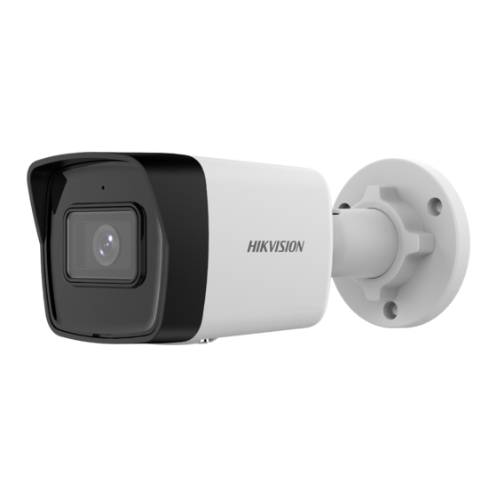
Page 12: Appearance Description
Network Bullet Camera·Quick Start Guide 1 Appearance Description Type I: Type I Bullet Camera Overview Type II: Type II Bullet Camera (PoE) Overview... - Page 13 Network Bullet Camera·Quick Start Guide Description Description Mounting Base Back Cover Front Cover IR LED Grounding Power Cord & Network Cable Type III: Type III Bullet Camera Overview Description Description Lens Front Cover...
- Page 14 Network Bullet Camera·Quick Start Guide Description Back Cover Mounting Base Power Cord Network Cable Type IV: Type IV Bullet Camera Overview Description Description Lens Front Cover Back Cover Mounting Base...
- Page 15 Network Bullet Camera·Quick Start Guide Description Power Cord Network Cable Type V: Type V Bullet Camera Overview Description Description Lens Front Cover Memory Card Slot Cover Back Cover Mounting Base Power Cord...
- Page 16 Network Bullet Camera·Quick Start Guide Description Network Cable Type VI: DC12 V IN Bullet Camera Overview Description Description Lens Main Body Bracket Power Cord Network Cable Microphone*...
- Page 17 Network Bullet Camera·Quick Start Guide Note: ● For cameras support power over Ethernet (PoE), the power is passed along with data on Ethernet cabling. And a switch supports PoE function is required. ● The items marked with the "*" are only supported by certain camera models.
-
Page 18: Installation
Network Bullet Camera·Quick Start Guide 2 Installation Before you start: ● Make sure the device in the package is in good condition and all the assembly parts are included. ● The standard power supply is PoE or 12 VDC, please make sure your power supply matches with your camera. -
Page 19: Ceiling Mounting
Network Bullet Camera·Quick Start Guide Unscrew the Cover and Insert Memory Card 2. Insert the memory card into the memory card slot. 3. (Optional)To unmount the memory card, push to get it ejected. 4. Screw the cover back to the camera. Ceiling Mounting Before you start: Both wall mounting and ceiling mounting are suitable for the bullet... - Page 20 Network Bullet Camera·Quick Start Guide 2. Drill the screw holes in the ceiling according to the supplied drill template. Note: Drill the cable hole, if adopting ceiling outlet to route the cable. Figure 2-2 The Drill Template 3. Route the cables through the cable hole (optional), or the side opening.
- Page 21 Network Bullet Camera·Quick Start Guide Note: In the supplied screw package, both self-tapping screws, and expansion bolts are contained. If the ceiling is cement, expansion bolts are required to fix the camera. If the ceiling is wooden, self-tapping screws are required. 5.
-
Page 22: Wall Mounting With Junction Box
Network Bullet Camera·Quick Start Guide P: 0° to 360° R: 0° to 360° T: -90° to 90° Figure 2-4 3-aix Adjustment 7. (Optional) Install the waterproof jacket. Refer to 2.4 Install Network Cable Waterproof Jacket for details. Wall Mounting with Junction Box Before you start: Both wall mounting and ceiling mounting are suitable for the ... - Page 23 Network Bullet Camera·Quick Start Guide Screw Hole Cable Hole Figure 2-5 The Drill Template 3. Take apart the junction box, and align the screw holes of the bullet camera with those on the junction box's cover. 4. Fix the camera on the junction box's cover with three PM4 × 10 screws.
- Page 24 Network Bullet Camera·Quick Start Guide Figure 2-7 Fix the Junction Box on the Wall 6. Route the cables through the cable hole. Here we take bottom cable hole as the example to describe the installation. Separate the water proof cover and the cable gland from the junction box.
-
Page 25: Install Network Cable Waterproof Jacket
Network Bullet Camera·Quick Start Guide Figure 2-8 Combine Junction Box's Cover with its Body 8. Repeat steps 5 to 7 of 2.2 Ceiling Mounting to complete the installation. Install Network Cable Waterproof Jacket If the camera is installed outdoor, you should use the waterproof accessory to waterproof the network cable. - Page 26 Network Bullet Camera·Quick Start Guide Steps: 1. Feed the network cable through ① and ③ in order. 2. Fix ② on the network cable between ① and ③. 3. Place ⑤ onto the end of ⑥, and plug the RJ45 male connector into RJ45 female connector.
-
Page 27: Activate And Access Network Camera
Network Bullet Camera·Quick Start Guide 3 Activate and Access Network Camera Scan the QR code to get Activate and Access Network Camera. Note that mobile data charges may apply if Wi-Fi is unavailable. - Page 28 UD18031B-E...