
Related Manuals for Asus AAEON BOXER-8256AI


Summary of Contents for Asus AAEON BOXER-8256AI
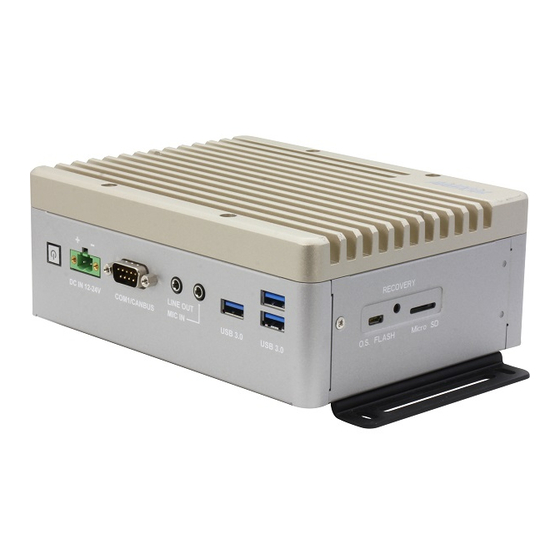
- Page 1 BOXER-8256AI AI@Edge Fanless Embedded AI System with NVIDIA ® Jetson Xavier™ NX User’s Manual 1 Last Updated: August 26, 2022...
- Page 2 Copyright Notice This document is copyrighted, 2022. All rights are reserved. The original manufacturer reserves the right to make improvements to the products described in this manual at any time without notice. No part of this manual may be reproduced, copied, translated, or transmitted in any form or by any means without the prior written permission of the original manufacturer.
- Page 3 Acknowledgements All other products’ name or trademarks are properties of their respective owners. NVIDIA®, the NVIDIA logo, Jetson™ and Jetson Xavier™ NX are trademarks of ⚫ the NVIDIA Corporation Ubuntu is a registered trademark of Canonical ⚫ All other product names or trademarks are properties of their respective owners. No ownership is implied or assumed for products, names or trademarks not herein listed by the publisher of this document.
- Page 4 Packing List Before setting up your product, please make sure the following items have been shipped: Item Quantity BOXER-8256AI ⚫ Power Connector ⚫ Wallmount Bracket ⚫ Screw Package ⚫ Power Adapter (optional) ⚫ Power Cord (optional) ⚫ If any of these items are missing or damaged, please contact your distributor or sales representative immediately.
- Page 5 About this Document This User’s Manual contains all the essential information, such as detailed descriptions and explanations on the product’s hardware and software features (if any), its specifications, dimensions, jumper/connector settings/definitions, and driver installation instructions (if any), to facilitate users in setting up their product. Users may refer to the product page at AAEON.com for the latest version of this document.
- Page 6 Safety Precautions Please read the following safety instructions carefully. It is advised that you keep this manual for future references All cautions and warnings on the device should be noted. All cables and adapters supplied by AAEON are certified and in accordance with the material safety laws and regulations of the country of sale.
- Page 7 As most electronic components are sensitive to static electrical charge, be sure to ground yourself to prevent static charge when installing the internal components. Use a grounding wrist strap and contain all electronic components in any static-shielded containers. If any of the following situations arises, please the contact our service personnel: Damaged power cord or plug Liquid intrusion to the device iii.
- Page 8 FCC Statement This device complies with Part 15 FCC Rules. Operation is subject to the following two conditions: (1) this device may not cause harmful interference, and (2) this device must accept any interference received including interference that may cause undesired operation.
- Page 9 China RoHS Requirements (CN) 产品中有毒有害物质或元素名称及含量 AAEON System QO4-381 Rev.A0 有毒有害物质或元素 部件名称 铅 汞 镉 六价铬 多溴联苯 多溴二苯 醚(PBDE) (Pb) (Hg) (Cd) (Cr(VI)) (PBB) 印刷电路板 × ○ ○ ○ ○ ○ 及其电子组件 外部信号 × ○ ○ ○ ○ ○ 连接器及线材 外壳 ○...
- Page 10 China RoHS Requirement (EN) Hazardous and Toxic Materials List AAEON System QO4-381 Rev.A0 Hazardous or Toxic Materials or Elements Component Name PCB and Components Wires & Connectors for Ext.Connections Chassis CPU & RAM HDD Drive LCD Module Optical Drive Touch Control Module Battery This form is prepared in compliance with the provisions of SJ/T 11364.
-
Page 11: Table Of Contents
Table of Contents Chapter 1 - Product Specifications..................1 Specifications ......................2 Chapter 2 – Hardware Information ..................4 Dimensions ....................... 5 Jumpers and connectors..................7 List of Jumpers ......................9 2.3.1 Setting Jumpers ..................9 2.3.2 Auto Power Setting (CN3) ..............10 List of Connectors .................... - Page 12 2.4.14 Line Out (CN33) ..................27 2.4.15 Mic In (CN34) ..................28 2.4.16 M.2 B-Key (CN38) .................. 29 2.4.17 M.2 E-Key (CN39) .................. 30 2.4.18 SATA Connector (CN40) ................ 31 2.4.19 USB 3.0 Connector (CN41) ..............31 2.4.20 LAN (RJ-45) Port (CN42) ..............32 2.4.21 RS-232/422/485 Select-COM2 (SW1) ..........
-
Page 13: Chapter 1 - Product Specifications
Chapter 1 Chapter 1 - Product Specifications... -
Page 14: Specifications
Specifications System AI Accelerator NVIDIA® Jetson Xavier™ NX 6-Core NVIDIA Carmel ARM®v8.2 64-bit CPU System Memory 8GB LPDDR4x Storage Device 16GB eMMC x 1 MicroSD slot x 1 M.2 M-Key 2280 x 1 (PCIe [x4]) Display Interface HDMI 2.0 x 2 Ethernet RJ-45 x 1 for GbE LAN USB3.2 Gen 1 Type-A x 3... - Page 15 Power Supply Power Requirement DC 12-24V with 2-pin terminal block Mechanical Mounting Wall-mount kit Dimensions (W x D x H) 7.09" x 5.35" x 2.64" (180 mm x 136 mm x 67 mm) Gross Weight 4.23 lbs. (1.92 kg) Net Weight 2.87 lbs.
-
Page 16: Chapter 2 - Hardware Information
Chapter 2 Chapter 2 – Hardware Information... -
Page 17: Dimensions
Dimensions Chapter 2 – Hardware Information... - Page 18 Chapter 2 – Hardware Information...
-
Page 19: Jumpers And Connectors
Jumpers and connectors Component Side Chapter 2 – Hardware Information... - Page 20 Module Side Chapter 2 – Hardware Information...
-
Page 21: List Of Jumpers
List of Jumpers The board has a number of jumpers that allow you to configure your system to suit your application. The table below shows the function of each of the board's jumpers. Label Function AT/ATX Mode Select 2.3.1 Setting Jumpers You configure your card to match the needs of your application by setting jumpers. -
Page 22: Auto Power Setting (Cn3)
2.3.2 Auto Power Setting (CN3) Function Open AT Close ATX (Default) List of Connectors The board has a number of connectors that allow you to configure your system to suit your application. The table below shows the function of each of the board's connectors. Label Function Jetson NX CPU Module Connector... - Page 23 CN23 RS232/RS422/RS485 Connector CN24 MicroSD Slot CN27 DC Power In connector CN33 Audio Line Out CN34 Audio Mic In CN37 SIM Socket CN38 M.2 B-Key CN39 M.2 E-Key CN40 SATA Connector CN41 USB 3.0 Connector CN42 Giga LAN Connector RS-232/RS422/RS-485 Select- COM2 RS-232/RS422/RS-485 Select- COM1 Recovery Switch Reset Switch...
-
Page 24: Jetson Nx Cpu Module Connector (Cn1)
2.4.1 Jetson NX CPU Module Connector (CN1) Chapter 2 – Hardware Information... -
Page 25: Rtc Connector (Cn2)
2.4.2 RTC Connector (CN2) Signal 2.4.3 UART Debug Port Connector (CN4) Signal Signal UART0 RXD UART0 TXD Chapter 2 – Hardware Information... -
Page 26: Usb 2.0 Flash Connector (Cn5)
2.4.4 USB 2.0 Flash Connector (CN5) Signal Signal VBUS 2.4.5 HDMI Out Connector 1 (CN6) Signal Signal HDMI_DATA2_P HDMI_DATA2_N HDMI_DATA1_P HDMI_DATA1_N HDMI_DATA0_P HDMI_DATA0_N HDMI_CLK_P HDMI_CLK_N HDMI_SCL HDMI_SDA HDMI_PWR HDMI_HDP Chapter 2 – Hardware Information... -
Page 27: Hdmi Out Connector 2 (Cn7)
2.4.6 HDMI Out Connector 2 (CN7) Signal Signal HDMI_DATA2_P HDMI_DATA2_N HDMI_DATA1_P HDMI_DATA1_N HDMI_DATA0_P HDMI_DATA0_N HDMI_CLK_P HDMI_CLK_N HDMI_SCL HDMI_SDA HDMI_PWR HDMI_HDP Chapter 2 – Hardware Information... -
Page 28: M-Key Connector (Cn12)
2.4.7 M.2 M-Key Connector (CN12) Chapter 2 – Hardware Information... - Page 29 Chapter 2 – Hardware Information...
-
Page 30: Usb 3.0 Connector (Cn15)
2.4.8 USB 3.0 Connector (CN15) Signal Signal VBUS VBUS (A)D- (B)D- (A)D+ (B)D+ (A)SSRX- (B)SSRX- (A)SSRX+ (B)SSRX+ (A)SSTX- (B)SSTX- (A)SSTX+ (B)SSTX+ Chapter 2 – Hardware Information... -
Page 31: Hdmi In Connector
2.4.9 HDMI In Connector *Please note that HDMI in application decodes via a HDMI in chipset. The application is different from the HDMI out connection to the monitor. Here are the limitations of the current HDMI in Chipset, especially for 4K 30fps usage on HDMI in: The HDMI source needs to have a stable output and pass the HDMI 2.0 signal integrity. -
Page 32: Hdmi In Connector 1 (Cn16)
2.4.9.1 HDMI In Connector 1 (CN16) Signal Signal HDMI_DATA2_P HDMI_DATA2_N HDMI_DATA1_P HDMI_DATA1_N HDMI_DATA0_P HDMI_DATA0_N HDMI_CLK_P HDMI_CLK_N HDMI_SCL HDMI_SDA HDMI_PWR HDMI_HDP Chapter 2 – Hardware Information... -
Page 33: Hdmi In Connector 2 (Cn17)
2.4.9.2 HDMI In Connector 2 (CN17) Signal Signal HDMI_DATA2_P HDMI_DATA2_N HDMI_DATA1_P HDMI_DATA1_N HDMI_DATA0_P HDMI_DATA0_N HDMI_CLK_P HDMI_CLK_N HDMI_SCL HDMI_SDA HDMI_PWR HDMI_HDP Chapter 2 – Hardware Information... -
Page 34: Hdmi In Connector 3 (Cn18)
2.4.9.3 HDMI In Connector 3 (CN18) Signal Signal HDMI_DATA2_P HDMI_DATA2_N HDMI_DATA1_P HDMI_DATA1_N HDMI_DATA0_P HDMI_DATA0_N HDMI_CLK_P HDMI_CLK_N HDMI_SCL HDMI_SDA HDMI_PWR HDMI_HDP Chapter 2 – Hardware Information... -
Page 35: Hdmi In Connector 4 (Cn19)
2.4.9.4 HDMI In Connector 4 (CN19) Signal Signal HDMI_DATA2_P HDMI_DATA2_N HDMI_DATA1_P HDMI_DATA1_N HDMI_DATA0_P HDMI_DATA0_N HDMI_CLK_P HDMI_CLK_N HDMI_SCL HDMI_SDA HDMI_PWR HDMI_HDP Chapter 2 – Hardware Information... -
Page 36: Sata Power 5V (Cn20)
2.4.10 SATA Power 5V (CN20) Signal Signal 2.4.11 COM Port Connector 1 (CN22) RS-232 RS-422 RS-485 CAN0 L CAN0 L CAN0 L CAN0 H CAN0 H CAN0 H Chapter 2 – Hardware Information... -
Page 37: Com Port Connector 2 (Internal) (Cn23)
2.4.12 COM Port Connector 2 (Internal) (CN23) RS-232 RS-422 RS-485 Chapter 2 – Hardware Information... -
Page 38: Power In Connector (Cn27)
2.4.13 Power In Connector (CN27) Signal Signal PWR_IN Chapter 2 – Hardware Information... -
Page 39: Line Out (Cn33)
2.4.14 Line Out (CN33) Signal Signal LINE_L LINE_R Chapter 2 – Hardware Information... -
Page 40: Mic In (Cn34)
2.4.15 Mic In (CN34) Signal Signal MIC_IN Chapter 2 – Hardware Information... -
Page 41: B-Key (Cn38)
2.4.16 M.2 B-Key (CN38) Chapter 2 – Hardware Information... -
Page 42: E-Key (Cn39)
2.4.17 M.2 E-Key (CN39) Chapter 2 – Hardware Information... -
Page 43: Sata Connector (Cn40)
2.4.18 SATA Connector (CN40) Signal Signal 2.4.19 USB 3.0 Connector (CN41) Signal Signal VBUS (A)D- (A)D+ (A)SSRX- (A)SSRX+ (A)SSTX- (A)SSTX+ Chapter 2 – Hardware Information... -
Page 44: Lan (Rj-45) Port (Cn42)
2.4.20 LAN (RJ-45) Port (CN42) Signal Signal MDI0+ MDI0- MDI1+ MDI1- MDI2+ MDI2- MDI3+ MDI3- Chapter 2 – Hardware Information... -
Page 45: Rs-232/422/485 Select-Com2 (Sw1)
2.4.21 RS-232/422/485 Select-COM2 (SW1) Mode 1T/1R RS-232 1T/1R RS-422 1T/1R RS-485 Low power shutdown 250kbps for RS-232 and RS-485/RS-422 RS-232 to 3Mbps and RS-485/RS-422 to 20Mbps Enable RS-422/RS-485 bias and termination resistors. Disable RS-422/RS-485 bias and termination resistors. Chapter 2 – Hardware Information... -
Page 46: Rs-232/422/485 Select-Com1 (Sw2)
2.4.22 RS-232/422/485 Select-COM1 (SW2) Mode 1T/1R RS-232 1T/1R RS-422 1T/1R RS-485 Low power shutdown 250kbps for RS-232 and RS-485/RS-422 RS-232 to 3Mbps and RS-485/RS-422 to 20Mbps Enable RS-422/RS-485 bias and termination resistors. Disable RS-422/RS-485 bias and termination resistors. Chapter 2 – Hardware Information... -
Page 47: Hardware Assembly
Hardware Assembly This section details the hardware assembly steps for the BOXER-8256AI. Please read this section thoroughly before beginning installation and ensure you have all necessary components ready. A Phillips head screwdriver is required. 2.5.1 Module Access & M.2 M-Key Installation The Xavier NX module is located under the top heat sink. -
Page 48: M.2 E-Key And B-Key Installation
2.5.2 M.2 E-Key and B-Key Installation The M.2 E-Key (2230) and B-Key (3042/3052) slots are accessible by removing the bottom panel. To access, remove the two (2) screws securing the bottom panel to the chassis, and then lift the panel off, as shown below. Follow standard procedures for expansion card installation, aligning the notch on each M.2 SSD with its respective key slot. -
Page 49: Hard Disk Drive (Hdd) Installation
2.5.3 Hard Disk Drive (HDD) Installation The hard disk drive bracket plate is accessible by removing the bottom panel. To access, remove the two (2) screws securing the bottom panel to the chassis, and then lift the panel off, as shown below. Remove the baseplate, then place the HDD on the bracket plate, then insert and tighten the four (4) screws to secure the HDD to the bracket plate. -
Page 50: Wall Mount Kit Installation
2.5.4 Wall Mount Kit Installation To install the wall mount kit, simply line up the brackets as shown and secure with four (4) screws (two for each bracket). Chapter 2 – Hardware Information... -
Page 51: Chapter 3 - Os Flash Guide
Chapter 3 Chapter 3 – OS Flash Guide... -
Page 52: Before Installation
Before Installation Before starting the process, make sure your BOXER-8256AI system is turned off and the power is disconnected. You will need a host PC running Ubuntu 18.04, and to ensure the NVIDIA Jetson Xavier NX module is installed onto the BOXER-8256AI carrier board system. -
Page 53: Connecting To Pc/Force Recovery Mode
Download the compressed OS image file. The file name will follow the format of: {PJ_IF}. {OS_IF}_{PLF_IF}{JPV_IF}_{IMGV_IF}_{BD_IF} For example: BOXER-8256AI.Ubuntu18.04_NXJP4.6.2_V1.0.0_23/06/2022 Note: Filename may differ from this example. {OS_IF} is OS Information; e.g. Ubuntu18.04 {PLF_IF} is Platform Information; e.g. NX {PJ_IF} is Project Information; e.g. BOXER-8256AI {IMGV_IF} is Build Number;... - Page 54 then release. The BOXER-8256AI should enter recovery mode. To check if device is in recovery mode, enter lsusb command in terminal on host. $ lsusb | grep “0955:7e19” If successful, the command will return “0955:7e19 Nvidia Corp” Recovery mode can be initiated with the system disassembled. Ensure the NVIDIA Jetson Xavier NX module is installed and refer to the image below to perform the steps: Chapter 3 –...
-
Page 55: Flash Image To Board
Flash Image to Board Use the following steps to flash the OS to the BOXER-8256AI. Open the terminal on Ubuntu host PC, then access the bootloader folder you extracted in the previous section. Enter the following command in terminal to flash the image: $ sudo ./flashboxer.sh Wait as the image is installed.