Table of Contents
Advertisement
Quick Links
Advertisement
Table of Contents

Related Manuals for Honeywell FEMA TAM Series


Summary of Contents for Honeywell FEMA TAM Series
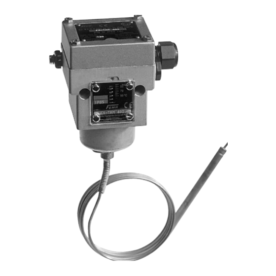
- Page 1 Assembly and Operating instructions Thermostats TAM, TRM, and TX series Basic models Additional functions TAM… …-205 TRM… …-206 TX… …-213 …-301 …-351 Ex-i …-513 Ex-de, Ex-t ® U.S. Registered Trademark MU2B-0375GE51 R0211A Copyright © 2011 Honeywell Inc. • All rights reserved...
- Page 2 Type code Type code Basic version Version with additional function Ex-version ABC XXX ABC XXX-YYY Ex-ABC XXX Identification for series Identification for temperature range Identification for additional functions Identification for Ex version MU2B-0375GE51 R0211A...
- Page 3 Type code Connection housings ABC XXX Plug connection housing (200) ABC XXX-2… (Plug connection to DIN EN 175301) ABC XXX-3… Terminal connection housing ABC XXX-5… (300 or 500) Ex- ABC XXX Ex-housing t (700) Important notes Thermostats are precision instruments, set and adjusted in factory. Do not open the device or reset the varnished adjustment screw.
- Page 4 Important safety information Important safety information Please read this before installing and commissioning! Installation and commissioning Caution when touching the device – Thermostats may only be installed by risk of burns. Device can reach on personnel trained in this application sensor side a temperature of up to area in accordance with installation 130 °C.
- Page 5 Prevent vibrations from reaching the thermostat, e.g., with mechanical isolation or other vibration damping measures. Never use thermostats as a climbing aid. Avoid condensation water when operating the device below 0 °C! Honeywell GmbH accepts no liability for non-compliance. MU2B-0375GE51 R0211A...
-
Page 6: Table Of Contents
Contents Contents Marking Basic equipment ABC XXX 1.1 Technical data 1.2 Mounting and installation 1.3 Electrical wiring and factory settings 1.4 Adjustment of switching points Thermostats with adjustable switching differential TRMV XXX, ABC XXX-303 Temperature limiter ABC XXX-205, -206 ABC XXX-305, -306 3.1 Temperature limiter with mechanical interlock 3.2 Interlock in control cabinet Thermostats with gold contacts ...-213... - Page 7 Contents Ex-proof thermostats (Ex-de, Ex-ti) Ex- ABC XXX 6.1 Technical data of Ex-proof switch-housings 6.2 Connection plan 6.3 Electrical ratings of components 6.4 Serial number 6.5 Setting of switching points MU2B-0375GE51 R0211A...
-
Page 8: Basic Equipment
1. Basic equipment 1. Basic equipment 1.1 Technical data (not for Ex-version) Chapter 1 describes the basic equipment, the technical data, the mounting and Installation electrical wiring of the thermostats. Vertical Switch Single-pole changeover Switching capacity 8 (5) A, 250 V AC Max. -
Page 9: Mounting And Installation
1. Basic equipment Fasten holding bracket (1) horizontal- 1.2 Mounting and installation ly on wall by means of screws and Wall installation plugs (6 mm diameter) With wall bracket H1 (included as Fasten terminal plate (3) by means of standard with room thermostats type 2 screws M4 on the reverse side of TRM). - Page 10 1. Basic equipment Wall fixing of the sensor cartridge by Sensor mounting in containers and means of clamping bracket H2 pipes For pressure-tight installation thermowells in 3 different lengths are available. For further accessories, see technical data sheets. Fig. 2. Fixing the sensor cartridge Fix clamping bracket (1) by means of 2 screws on the wall.
- Page 11 1. Basic equipment Remove fixing screw 1.3 Electrical wiring Insert screwdriver into the split and Plug connection (Housing 2...) press downwards. The part with terminals will move out of the housing. Pull connecting cable (7) through conduit and wire contacts according to plan.
- Page 12 1. Basic equipment Screw terminal connection Factory adjustment (Housing 3... and 5...) With falling temperature, switching occurs Accessible after removing cover at screw at the set scale value. Switching back (as terminal housing. soon as temperature begins to rise) occurs at a value higher by the amount of the switching differential.
- Page 13 1. Basic equipment Wiring diagrams Fig. 4. Monitor Fig. 5. Maximum limiter As the temperature rises Additional function -205, -305 3-1 opens, 3-2 closes As the temperature falls 3-2 opens, 3-1 closes Fig. 6. Minimum limiter Additional function -206, -306 MU2B-0375GE51 R0211A...
-
Page 14: Adjustment Of Switching Points
1. Basic equipment The grub screw (12) located above the 1.4 Adjustment of switching scale is to be slackened off approx. points 2 turns before making an adjustment and tightened up again after setting. Fig. 7. Adjustment of switching points Turning to the right lower switching point Turning to the left... - Page 15 1. Basic equipment In general adjustment procedure of CAUTION switchpoints at screw terminal housing is Switch off power before opening. similar to procedure for plug connector housing. After removal of the casing-cover (1), the adjustment screw (3) and thus also the setpoint (4) can be adjusted to the required value by means of a screwdriver.
-
Page 16: Thermostats With Adjustable Switching Differential
2. Thermostats with adjustable differential 2. Thermostats with adjustable CAUTION differential With TRM...-303, there is a risk of The switching differential is changed by touching the mains power. Therefore, turning the grub screw (2) inside the switch off power. setting screw (1). The switching point is not changed by adjusting the differential, Turning to the right only the reset point is shifted by the... -
Page 17: Temperature Limiter
3. Temperature limiter 3. Temperature limiter Min. temperature limitation (…-206) When temperature falls below the value 3.1 Temperature limiter with set on the scale, the microswitch switches mechanical interlock over and remains in this position. The catch can be released by pressing the Max. -
Page 18: Interlock In Control Cabinet
3. Temperature limiter 3.2 Interlock in control cabinet A thermostat can act as a temperature limiter if interlock function is provided by electrical circuitry. Below are two examples for interlock circuitry. In any case, valid standards (e.g., DIN EN 50156 / VDE 0116-1 and valid local standards) must be observed for design of electrical interlocking circuitry. - Page 19 3. Temperature limiter Maximum temperature limitation Minimum temperature limitation Fig. 10. Max. temperature limitation Fig. 11. Min. temperature limitation TW = Thermostat S = Signal (if required) T1 = STOP K1 = Relais with catch contact T2 = START SC = Safecty circuit MU2B-0375GE51 R0211A...
-
Page 20: Thermostats With Gold Contacts
4. Thermostats with gold-plated contacts ...-213 4. Thermostats with gold- 4.1 Technical data as per 1.1 plated contacts ...-213 Switching capacity max. 24 V DC Gold-plated contacts are used exclusively max. 100 mA in the low-voltage range in order to keep min. -
Page 21: Thermostats In Intrinsic Safe Circuits Ex-I
5. Thermostats in intrinsic safe circuits Ex-i 5. Thermostats in intrinsic safe The wiring diagram applies for max. pressure monitoring. circuits Ex-i At rising pressure contact 3-1 opens and according to chapter 5.7 of EN 60079- 3-2 closes. 11, "Simple electrical apparatus". Installation only in combination with a Gold contacts SPDT. - Page 22 5. Thermostats in intrinsic safe circuits Ex-i Ratings Max. switching load: 24 VDC, 50 mA Min. switching load: 5 VDC, 2 mA Operation of the pressure switch only within the allowed specification limits. During selection of a suitable switching amplifier and planning of wiring lengths the following parameters must be observed: = max.
-
Page 23: Technical Data Of Ex-Proof Switch-Housings
6. Ex-proof thermostats (Ex-de, Ex-t) 6. Ex-proof thermostats (Ex-de, Type of protection IP 65 Ex-t) Ambient temperature Ex-proof thermostats from “flameproof –20 bis +60 °C enclosure” must be supplied in the form that has been type test approved Max. temperature at switching device according to ATEX. -
Page 24: Connection Plan
6. Ex-proof thermostats (Ex-de, Ex-t) 6.2 Connection plan 6.3 Electrical ratings of components The terminal board can be accessed after the protective casing has been removed. After connecting the supply lines, the Microswitch protective casing should in all cases be Voltage rating reattached. -
Page 25: Serial Number
6. Ex-proof thermostats (Ex-de, Ex-t) Wiring terminals (Housing 700) 6.4 Serial number Voltage rating All switch units and their respective Up to 440 V terminal board casings are marked with a Current rating serial number. Max. 23 A When installing, you should ensure that Tightening torque the terminal board casings do not get Max. -
Page 26: Setting Of Switching Points
6. Ex-proof thermostats (Ex-de, Ex-t) 6.5 Setting of switching points 1. Potential equalization 2. Protective casing for terminals (removable) 3. Connection terminals 4. Cable inlet M16 x 1.5 For fixed installation only! 5. Switching point adjustment 6. Locking bolt for setting spindle 7. - Page 27 6. Ex-proof thermostats (Ex-de, Ex-t) The switching point can be set within the range given in the datasheet by using a screwdriver on the setting spindle. Additionally, you should remove the terminal board casing (with 4 hexagon screws M4). The affixing screw on the front end (above the scale) has to be removed and should be reattached after setting the switching point.
- Page 28 Manufactured for and on behalf of the Environmental and Combustion Controls Division of Honeywell Technologies Sàrl, Rolle, Z.A. La Pièce 16, Switzerland by its Authorized Representative. Honeywell GmbH FEMA Controls Böblinger Strasse 17 71101 Schönaich Germany Phone: 07031/637-02 Fax: 07031/637-850 MU2B-0375GE51 R0211A www.fema.biz...
- Page 29 Mouser Electronics Authorized Distributor Click to View Pricing, Inventory, Delivery & Lifecycle Information: Honeywell TAM490 TAM150-301 TAM150-305 TAM150-351 TAM490-205 TAM813 TAM813-563 TAM022-513 TAM022- 351 TAM150-213 TAM813-205 TAM022 TAM490-351 TAM490-305 TAM490-301 TAM490-213 TAM022-206 TAM490-513 TAM150 TAM022-301 TAM813-313 TAM022-306 TAM813-351 TAM813-513 TAM813-305 TAM813-...