Advertisement
Quick Links
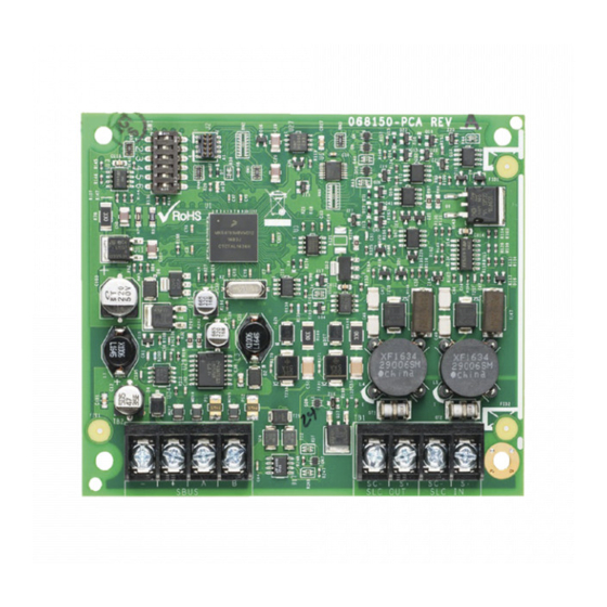
1.1 Description
The 6815 SLC expander lets you add additional addressable devices to a compatible Fire Alarm Control Panels (FACP). Installation and wiring of
this device must be done in accordance with NFPA 72 and local ordinances.
1.2 Compatibility
The 6815 is for use with compatible Honeywell Silent Knight and Farenhyt Series Fire Alarm Control Panels FACP's:
NOTE:
For compatibility, programming and more information see FACP installation manual.
1.3 Specifications
• Standby Current: 78mA
• Alarm Current: 78mA
• Operating Voltage: 24VDC
• Operating Temperature: 32°F to 120°F (0°C to 49°C)
1.4 Mounting
You can mount the 6815 in a compatible FACP cabinet, in the 5895XL or RPS-1000 intelligent power module cabinet, or in the SK-NIC-KIT
remote mounting kit.
WARNING:
!
The electronic components on the 6815 and the panel are sensitive to electrostatic discharge. Wear a grounding strap when
handling any of the boards.
To mount the 6815:
1.
Remove power from the panel.
2.
If mounting the 6815 in an FACP or 5895XL, use the standoffs located under the panel assembly and secure with screws provided with the
6815.
–OR–
3.
If mounting the 6815 in a 5815RMK or SK-NIC-KIT orientate the 6815 board(s) as shown in Figure 1.1 and snap into place on the plastic
standoffs.
Figure 1.1 Standoff Installation and 6815 Board Mounting
6815 SLC Expander
Product Installation Document
PN LS10173-001SK-E:A 07/01/2017 16-0218
Advertisement

Related Manuals for Honeywell 6815


Summary of Contents for Honeywell 6815
- Page 1 If mounting the 6815 in an FACP or 5895XL, use the standoffs located under the panel assembly and secure with screws provided with the 6815. –OR– If mounting the 6815 in a 5815RMK or SK-NIC-KIT orientate the 6815 board(s) as shown in Figure 1.1 and snap into place on the plastic standoffs. Figure 1.1 Standoff Installation and 6815 Board Mounting...
- Page 2 Figure 1.2 6815 Connection to the Control Panel 1.6 Setting DIP Switches Use the on-board DIP switches to select an ID number for the 6815. Refer to Figure 1.3 to see how to set the DIP switches for the desired ID num- ber.