Table of Contents
Advertisement
Quick Links
Advertisement
Table of Contents

Related Manuals for Kenwood GP-610A


Summary of Contents for Kenwood GP-610A
- Page 1 GP-61OA/GP-61OD G P - I B A D A P T E R INSTRUCTION MANUAL KENWOOD CORPORATION...
- Page 2 FCC WARNING: T h i s equipment may g e n e r a t e or use r a d i o f r e q u e n c y e n e r g y . Changes or m o d i f i c a t i o n s to t h i s equipment may cause h a r m f u l i n t e r f e r e n c e u n l e s s...
-
Page 3: Table Of Contents
Connect ion of the Control led Power Supply 1) Connecting GP-G10D with PD power supply • 2) Connecting GP-610A with PA power supply 3) Analog output connect ion 4) D i g i t a l I/O connection Code Format Setting Total System Adjustment 7 . -
Page 4: Outline
1. OUTLINE This adapter i s used to set the constant voltage or constant current and control the OUTPUT switch on/off our PD or PA s e r i e s DC regulated power supply from a computer by using the GP-IB bus (IEEE-488-1978). •... -
Page 5: Specifications
2. SPECIFICATIONS [GP-IB] E l e c t r i c a l s p e c i f i c a t i o n s : IEEE488 1978 Mechanical speci f icat ions : IEEE488-1978 Interface function : SHI, AH1, T6, L3, SRI, RL1, PPO, DC1, DTI, CO Address setting : Address 0 to 30 can be a r b i t r a r i l y set by using the address switch. - Page 6 Temperature c o e f f i c i e n t : 50 ppm/°C ( t y p i c a l ) Rising time i n n 1 U U / / S r l e S S (10 to 90%, 10 kiloohm load) °...
- Page 7 [Dimensions] 68 (W) x 147 (H) x 251 (D)mm (Cabinet) 73 (W) x 161. 5 (11) x 284 (D)mm (Maximum s i z e ) [Weight] Approximately 2. 3 kg [Accessor i e s ] CP-610A : Instruct ion manual : 1 Replacement fuse OP-15 r 3-pin DIN - 2-pin cable: 2 .
-
Page 8: Precautions For Use
• Complete connect ions before power on and check that the connect ions are correct. • Power on/off order should be as shown below. • Do not replace the connector while power i s on. GP-610A GP-610D Controlled power supply This component Be s u r e to ground the GND t e r m i n a l of t h i s component and the GND terminal of the controlled power supply. - Page 9 • Note on connect i ng the s h o r t bar When t h i s component i s used in a combination w i t h a f l o a t i n g c i r c u i t type power supply (PD or PA s e r i e s ) , normal operation may not be done depending on connect ion of the short bar i f the power input cord of the PD or PA power supply i s the 3-pin type.
-
Page 10: Theory Of Operation
4. SYSTEM CONFIGURATION Theory of Operat ion The block diagram of t h i s component i s shown below. The d i g i t a l s i g n a l input from the GP-IB c o n n e c t o r i s f e d to t h e GP-IB interface 1C v i a the bus transceiver. - Page 11 System C o n f i g u r a t i o n To configure a system of t h i s component and the pwoer supply, c a r e f u l ly examine the s p e c i f i c a t i o n s of t h i s component and the power supply. I/O s p e c i f i c a t ions of t h i s component 12 b i t s ( b i n a r y ) 1 .
-
Page 12: E X P L A N A T I O
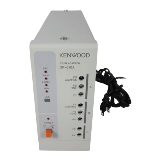
*1 When control in 2) above i s done by using this component, the EXT 1/0 in t e r f a c e for CP-IB, OP-12 or OP-13 (opt ion), should have been incorpo- rated into the PD or PA power supply. For d e t a i l s , contact the s a l e s o f f i c e of our Measuring Equipment D i v i - sion. - Page 13 5. INDICATORS AND CONTROLS Rear panel Front panel Note: The figure shows GP-610A. ® POWER Power switch. I f this switch i s pressed, the POWER LED goes on. ® POWER LED This LED i s on during operation. (D LCL Remote/local changeover switch.
- Page 14 ® This LED indicates the remote mode. This LED i s on in remote mode ( i . e . power supply being controlled through the GP-IB bus). ® LISTEN This LED indicates the l i s t e n mode. 11 i s on whi1e the 1istener i s s p e c i f i e d on the CP-IB bus.
- Page 15 CH B OV Channel B output offset adjustment semi-fixed v a r i a b l e r e s i s t o r ® CH C FS Channel C output voltage adjustment semi-fixed v a r i a b l e r e s i s t o r ( 1 turn) ©...
- Page 16 Address switch The address of t h i s component on the GP-IB bus and the l i s t e n - o n l y mode are set. ® GND terminal SIGNAL: Signal grounding to which the c i r c u i t ground i s connected FRAME : Frame grounding to which the case i s connected Be sure to perform grounding to secure safety and to prevent malfunctions due to external noise.
-
Page 17: Operating Procedure
6. OPERATING PROCEDURE Each P a r t S e t t i ng and Connect i on GP-IB bus cable s e t t i n g . By using the GP-IB bus cable, connect the GP-IB connector of this component to the c o n t r o l l e r . - Page 18 • By turning on the L. ONLY switch, the listen-only mode can be set. (Switch 6) Note : • Other switches (7 and 8) are not used. Be sure to set them to OFF. • The contents set by the address swi tch are read upon power on. Be sure to set the address switch before power on.
-
Page 19: Connecting Gp-G10D With Pd Power Supply • 1
Connect i on of the Cont r o I Ied Power SuppIy Connecting GP-610D with PD power suppIy Rear view of the PD series Rear view of GP-610D Black (3-pin DIN connector) Constant current s e t t i n g OUTPUT A White (3-pin DIN connector) -
Page 20: Connecting Gp-610A With Pa Power Supply 1
Connecting GP-610A with PA power supply ® When OP-13 i s attached When OP-13 i s mounted on the PA s e r i e s CP610A CP IB LOCAL MASTER REMOTE SLAVE (3-pin DIN connector) PARALLEL OUTPUT A OUTPUT... - Page 21 ® When OP-13 i s not attached PA s e r i e s without OP-13 GPG10A LOCAL MASTER REMOTE REMOTE (3-pin DIN connector) OUTPUT A PARALLEL C. V REMOTE C. C REMOTE OUTPUT OPERATE (3-pin DIN connector) Black! OUTPUT B Black OUTPUT C Note: By s e t t i n g...
-
Page 22: Analog Output Connect Ion 1
Analog output connection The analog output voltage of t h i s component i s fed to the pin "which cont- r o l s the output voltage with an e x t e r n a l voltage" or "which c o n t r o l s the output c u r r e n t w i t h an e x t e r n a l voltage"... -
Page 23: D I G I T A L I/O Connection 2
GP-610A PA power supply GP-610A Si REMOTE Constant vol I age setting OUTPUT A D/A output - Black S2 REMOTE Constant current setting OUTPUT B D/A output - Black OUTPUT C I)/A outpul Black Note: For connect ing the CV/CC e x t e r n a l control without OP-13, connect the... - Page 24 CONTROL A or I! TPin DIN OP 12 Tl'in DIN OUTPUT ON/OFF CV/tT POWER ON OFF PA s e r i e s PA power supply GP-610A CONTROL A or [1 TPin DIN Brown OUTPUT ON III'F Ye I low cv/tT Black Blue...
-
Page 25: Code Format Setting 2
Code F o r m a t Set t i n g This component operates by receiving the ASCII code through the PC-IB bus. Describe the necessary code characters for control of t h i s component upon pro- gramming into the computer. The code characters are converted into ASCII codes and output to the GP-IB bus. - Page 26 GP-IB input code format Setting of the control led power supply F u l l - s c a l e voltage/current value of the control led power supply (1 to 3 d i g i t s including decimal point) Example: 8 V->8 1.
- Page 27 Each channel output data s e t t i n g Out put data s e t t i n g value (1 to 5 d i g i t s including decimal point) Two d i g i t s below decimal point. Example: 6.
- Page 28 (SRQ) i s generated for the GP-IB bus. In t h i s case, the d e t a i I s can be known by reading the status byte. The following SRQ generating causes are provided for GP-610A/D: Status byte (6111) ©...
- Page 29 Input s e t t i n g error : S e t t i n g d e v i a t e s from the s p e c i f i e d set- ting range. • C u r r e n t output d a t a i s input to the voltage sett ing channel.
- Page 30 Processing the SRQ factor in each mode Address ibIc mode SRQ cause for the input syntax error : This component accepts the cause and generates SRQ. SRQ cause for the input s e t t i n g error : This component accepts the cause and generates SRQ.
- Page 31 F u l l - s c a l e adjustment i s done by using the FS semi-solid v a r i a b l e r e s i s t o r on the panel of GP-610A/D.
- Page 32 F u l l - s c a l e adjustment i s done by using the FS semi-solid v a r i a b l e r e s i s t o r on the panel of GP-610A/I).
-
Page 33: Program Application Examples
7. PROGRAM APPLICATION EXAMPLES * Program example The voltage/current of PD35-20 i s controlled. P D 3 5 - 2 0 Controller G P - 6 1 0 D Connect ion r- OUTPUT A : Voltage s e t t i n g - OUTPUT B : Current s e t t i n g - CONTROL A: Control terminal ADDRESS... - Page 34 * Program example Voltage of PD35-20 and PD18-20 arc controlled. Note: Set the PD35-20 CURRENT dial G P - 6 1 0 D of the ncccs- Controller ssary value. PD18-20 Connection OUTPUT A : PD35-20 voltage setting OUTPUT B : PD18-20 voltage setting CONTROL A: PD35-20 control terminal CONTROL B: PD18-20 control terminal ADDRESS...
- Page 35 • Application example Application program Battery automatic recharging PD18-10 GP-610D Controller Connect ion OUTPUT A : PD18-10 voltage s e t t i n g OUTPUT B : PD18-10 current s e t t i n g CONTROL A: PD18-10 control terminal ADDRESS REM **** SAMPLE 3 **** SRQ=0...
-
Page 36: Maintenance
8. MAINTENANCE • How to remove the case Remove the case a f t e r power i s turned o f f and the power cord i s removed from the outlet. By us ing a Phi 1ips screwdr i v c r , remove two screws on the top of the case and s i x screws on the sides of the case. - Page 37 * Power voltage change For switching the rated input voltage, open the case and change the connectors (P4, 5, 6) and fuse on the GP-IB unit (X81-1630 00) in the component as shown below. Note: Before the change, remove the AC plug from the out l e t . Rated input 100 V 100V...
-
Page 38: External View
9. EXTERNAL VIEW - 3 5 -... -
Page 39: 0 . Mounting Ont H E Rack-Mount A D A P T E
10. MOUNTING O N THE RACK-MOUNT ADAPTER GP-610A : RK-604J (.MS) RK-604E ( E I A ) GP-610D : RK-601 ( J I S / E I A ) This component can be mounted on the rack-mount adapter shown above. - Page 40 A product of KENWOOD C O R P O R A T I O N 1 7 - 5 , 2 - c h o m e . S h i b u y a . S h i b u y a - k u .