Advertisement
Quick Links
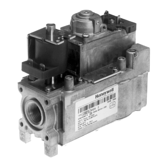
GAS CONTROL WITH INTEGRATED 1:1 GAS/AIR REGULATOR FOR
APPLICATION
VR4611VA 1007 gas control has been specially developed for
application in domestic premix appliances with intermittent
pilot ignition.
VR4611VA 1007 gas control is used in a system context in
conjunction with fan control, an intermittent pilot ignition (IP)
control module and associated devices to provide
programmed safe light--up and supervision of the main burner
of an appliance.
VR4611VA 1007 gas control is intended to be used for natural
gas and LP gas.
VR4611VA 1007 gas control is approved in accordance with
existing european standards.
DESCRIPTION
VR4611VA 1007 gas control performs all the functions
required to safely regulate gas flow to the main burner of
domestic central heating equipment, warm air furnaces, back
boilers and water heaters.
VR4611VA 1007. gas control consists of a first direct electric
ON/OFF operator for opening the safety valve of class B
according to EN 161 and a second electric ON/OFF servo
operator valve for opening the main valve of class C and J
according to EN 161.
VR4611VA1007
AUTOMATIC IGNITION SYSTEMS
SPECIFICATIONS
Model
VR4611VA 1007: line voltage, fast opening, with
integrated 1 : 1 gas/air regulation, low capacity, and
with two automatic shut off valves for intermittent
pilot ignition (IP) applications.
Dimensions
See fig. 1.
Ambient temperature
0 ... 70 _C
Pressure regulation function
Class C according to EN 88
Pipe size
Pipe connections are designed to meet the bending stress of
group 2 according to EN 161.
1
Inlet and outlet:
/
" ISO 7--1 internal parallel pipe thread.
2
Inlet and outlet can also be made with straight or elbow
flanges.
Air pressure connection
Servo pressure regulator has an M5 threaded hole to make
connection between regulator and appliance.
Maximum air pressure
8 mbar without outlet gas pressure (before ignition)
20 mbar with outlet gas pressure present (after ignition)
Minimum regulation capacity
3
0.5 m
air/
at ,p=0.5 mbar across the main burner injector
h
and 30 mbar maximum operating pressure.
3
0.7 m
air/
at ,p=0.5 mbar across the main burner injector
h
and 60 mbar maximum operating pressure.
Minimum operating gas pressure
15 mbar
Offset range
-- 0.4 mbar ... + 0.2 mbar
gas control in 90_ from upright position (first coil horizontal)
-- 0.25 mbar ... + 0.2 mbar
gas control in upright position (first coil vertical)
Maximum operating gas pressure
The P
60 mbar indication on the housing is the maximum
max
inlet pressure at which the gas control functions safely.
Capacity (measured with throttle open,1013 mbar and 15 _ _ _ _ C)
3
4.2 m
/h air at ,p = 10 mbar.
Curve is available on request.
INSTRUCTION SHEET
EN1R- -9170 0109R1- -NE
Advertisement

Related Manuals for Honeywell VR4611VA1007


Summary of Contents for Honeywell VR4611VA1007
- Page 1 VR4611VA1007 GAS CONTROL WITH INTEGRATED 1:1 GAS/AIR REGULATOR FOR AUTOMATIC IGNITION SYSTEMS INSTRUCTION SHEET SPECIFICATIONS Model VR4611VA 1007: line voltage, fast opening, with integrated 1 : 1 gas/air regulation, low capacity, and with two automatic shut off valves for intermittent pilot ignition (IP) applications.
- Page 2 Electrical data Timing Closing time: ±1 s Power consumption at 220/240 V Opening time: ±1 s from start of flow till outlet pressure operator: 3.6/4.7 W is 1 mbar. operator: 3.4/4.5 W Enclosure Current at 220/240 V IP 40: when used with covers or plugs operator: 32/36 mA IP 44: when used with DIN plugs according to DIN 43650 operator: 20.4/24 mA...
- Page 3 INSTALLATION Perform gas leak test WARNING IMPORTANT FIRE OR EXPLOSION HAZARD CAN CAUSE Take care that installer is a trained experienced ser- PROPERTY DAMAGE, SEVERE INJURY OR vice person. DEADTH Turn off gas supply before starting installation. Check for gas leaks with a rich soap and water solu- Disconnect power supply to prevent electrical shock tion any time work is done on a gas control.
- Page 4 The oscillation has to be verified for the complete replaceable components. modulation band of the appliance. Attempted disassembly or repair may damage the gas Please contact your Honeywell representative if the control maximum of 10 % is exceeded. Screws on the valve that have been sealed must Oscillation outlet pressure to be recorded with never be removed.