Table of Contents
Advertisement
Quick Links
Technical Manual
Of
Intel Elkhart Lake Series CPU
Based IPC M/B
NO. G03-MF13-F
Revision: 1.0
Release date: July 21, 2022
Trademark:
* Specifications and Information contained in this documentation are furnished for information use only, and are
subject to change at any time without notice, and should not be construed as a commitment by manufacturer.
Advertisement
Table of Contents

Related Manuals for JETWAY MF13


Summary of Contents for JETWAY MF13
- Page 1 Technical Manual Intel Elkhart Lake Series CPU Based IPC M/B NO. G03-MF13-F Revision: 1.0 Release date: July 21, 2022 Trademark: * Specifications and Information contained in this documentation are furnished for information use only, and are subject to change at any time without notice, and should not be construed as a commitment by manufacturer.
- Page 2 Environmental Protection Announcement Do not dispose this electronic device into the trash while discarding. To minimize pollution and ensure environment protection of mother earth, please recycle.
-
Page 3: Table Of Contents
TABLE OF CONTENT ENVIRONMENTAL SAFETY INSTRUCTION ............... iv USER’S NOTICE ........................v MANUAL REVISION INFORMATION ................... v ITEM CHECKLIST ........................ v CHAPTER 1 INTRODUCTION OF THE MOTHERBOARD FEATURE OF MOTHERBOARD ................1 SPECIFICATION ....................2 LAYOUT DIAGRAM ....................3 CHAPTER 2 HARDWARE INSTALLATION JUMPER SETTING .................... -
Page 4: Environmental Safety Instruction
Environmental Safety Instruction Avoid the dusty, humidity and temperature extremes. Do not place the product in any area where it may become wet. 0 to 60 centigrade is the suitable temperature. (The figure comes from the request of the main chipset) ... -
Page 5: User's Notice
USER’S NOTICE COPYRIGHT OF THIS MANUAL BELONGS TO THE MANUFACTURER. NO PART OF THIS MANUAL, INCLUDING THE PRODUCTS AND SOFTWARE DESCRIBED IN IT MAY BE REPRODUCED, TRANSMITTED OR TRANSLATED INTO ANY LANGUAGE IN ANY FORM OR BY ANY MEANS WITHOUT WRITTEN PERMISSION OF THE MANUFACTURER. -
Page 6: Chapter 1 Introduction Of The Motherboard
Support 1* SATAIII (6Gb/s) Device & 1* SIM card slot Support 1* External USB3.1(Gen.2), 1* External USB2.0, 2* Internal USB2.0 Support 4* i225V 2.5GbE RJ-45 LAN ports Onboard 32GB eMMC (Option for MF13-03 series) Onboard Lockable 12V DC-in PWR jack Support CPU Over-Temperature protection ... -
Page 7: Specification
1* SATAIII 6Gb/s port 1* M.2 M-key (2242/2280, SATA/PCIe Gen.3x2 interface) support Storage NVMe (M2M) Onboard 32GB eMMC (optional for MF13-03) BIOS AMI Flash ROM 1* Lockable 12V DC-in power Jack 1* USB 3.1(Gen.2) port ... -
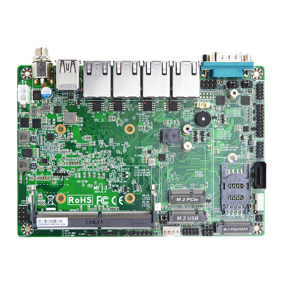
Page 8: Layout Diagram
1* 9-pin USB 2.0 header (Expansible to 2* USB 2.0 ports) * RS232/422/485 serial port header (FP_COM2) 1* PS/2 keyboard & mouse header 1* SMBUS header 1* GPIO header 1* HDMI header 1-3 Layout Diagram Rear IO Panel Diagram: 12V DC-in 2.5Gbps RJ-45 LAN Ports... - Page 9 Motherboard Internal Diagram-Front Side SATA Power-out Connector HDMI1 Header USB 2.0 Header RS232/422/485 JPCAS_80P Serial Port Header (FP_COM2) SATA III Port JPCOM2 *SIM Card Slot M.2 M-key Slot JPCOM1 (M2M) RS232/422/485 Serial Port (COM1) LAN_LED Header BATCON M2M_PWR JBAT M.2 E-key Slot (M2E1) GPIO Header M.2 B-key Slot (M2B1)
- Page 10 Connectors Connector Name DCIN1 Lockable 12V DC-in power Jack USB31 Top: USB 2.0 Port Connector Bottom: USB 3.1(Gen.2) Port Connector LAN1/2/3/4 2.5Gbps RJ-45 LAN Port Connector x 4 COM1 RS232/485/422 Serial Port Connector ATXPWR Internal 12V DC–in Power Connector SATA1 SATAIII Connector SATAPWR SATA Power-out Connector...
-
Page 11: Chapter 2 Hardware Installation
Jumpers Jumper Name Description Pitch AT_MODE ATX Mode/AT Mode Select 3-Pin Block 2.0mm JBAT Pin (1&2): Clear RTC 6-Pin Block 2.0mm Pin(3&4): Clear CMOS Pin(5&6): ME Disable JPCAS_80P Pin (1&2): SHORT_CASE OPEN 4-Pin Block 2.0mm Pin(3&4): SHORT_80 PORT JPCOM1 COM1 Pin9 Function Select 4-Pin Block 2.0mm JPCOM2... - Page 12 AT Mode Selected: Directly power on as power input ready. Pin (1-2) of JBAT (6-pin): Clear RTC Pitch=2.0mm Pin 1 1-2 Open: Normal(Default); JBAT Pin 1 1-2 Closed: Clear RTC. Pin (3-4) of JBAT (6-pin): Clear CMOS Pitch=2.0mm Pin 1 JBAT 3-4 Open: Normal(Default);...
- Page 13 Pin (5-6) of JBAT (6-pin): ME Disable Pitch=2.0mm JBAT Pin (1-2) of JPCAS_80P (4-pin): SHORT_CASE OPEN Pitch=2.0mm JPCAS_80P...
- Page 14 PIN (3-4) of JPCAS_80P (4-pin): SHORT_80 PORT Pitch=2.0mm JPCAS_80P JPCOM1 (4-pin) :COM1 Pin9 Function Select Pitch=2.0mm JPCOM1 COM1 2-4 Closed: 3-4 Closed: 4-6 Closed: RI=RS232 RI=5V RI=12V...
- Page 15 JPCOM2 (4-pin) :FP_COM2 Pin9 Function Select Pitch=2.0mm FP_COM2 JPCOM2 2-4 Closed: 3-4 Closed: 4-6 Closed: RI=RS232 RI=5V RI=12V M2B_PWR (3-pin): M.2 B-key Power Select Pitch=2.0mm M2B_PWR...
- Page 16 M2E_PWR (3-pin): M.2 E-key Power Select Pitch=2.0mm M2E_PWR M2M_PWR (3-pin): M.2 M-key Power Select Pitch=2.0mm M2M_PWR...
-
Page 17: Connectors And Headers
Connectors and Headers 2-2-1 Connectors (1) Rear I/O Connectors 12V DC-in 2.5Gbps RJ-45 LAN Ports PowerConnector (LAN 1/2/3/4) USB 2.0 Port (Lockable) RS232/485/422 COM1 Serial Port USB 3.1(Gen.2) Port Icon Name Function For user to connect compatible power 12V DC-in Power adapter to provide power supply for the Connector (Lockable) system. - Page 18 Mainly for user to connect external MODEM RS232/485/422 Serial Port or other devices that supports Serial Communications Interface. (2) ATXPWR (2-pin Block): Internal 12V DC-in Power Connector ATXPWR (3) SATA1 (7-pin): STATIII Port Connector SATA1 is a high-speed SATAIII port that supports 6Gb/s transfer rate. SATA1 Pin No.
- Page 19 (4) SATAPWR (4-pin): SATA HDD Power-Out Connector SATAPWR Warning: Make sure that Pin-1 of compatible SATA Power connector is inserted into corresponding Pin-1 of SATAPWR to avoid possible damage to the board and hard disk driver! (5) CPUFAN (4-pin): CPU FAN Connector Control Fan Speed +12V Fan Power...
-
Page 20: Headers
2-2-2 Headers (1) JW_FP (8-pin): Front Panel Header Pitch=2.54mm JW_FP (2) SMBUS (5-pin): SM BUS Header Pitch=2.0mm SMBUS... - Page 21 (3) PS2KBMS (6-pin): PS/2 Keyboard & Mouse Header Pitch=2.54mm PS2KBMS (4) GPIO (10-pin): GPIO Header Pitch=2.0mm GPIO_86 GPIO_87 GPIO GPIO_85 GPIO_84 GPIO_82 GPIO_83 GPIO_80 GPIO_81 Pin1...
- Page 22 (5) FP_USB21 (9-pin): USB 2.0 Port Header Pitch=2.0mm FP_USB21 (6) HDMI1 (19-pin): HDMI Port Header Pitch=2.0mm HDMI1...
- Page 23 (7) FP_COM2 (9-pin): Serial Port Header (support RS232/422/485) Pitch=2.0mm FP_COM2 (8) LAN_LED (8-pin): LAN Activity LED Header Pitch=2.54mm LAN4_ACT- LAN4_LED_VCC LAN3_ACT- LAN3_LED_VCC LAN2_ACT- LAN2_LED_VCC LAN1_ACT- LAN1_LED_VCC Pin 1 LAN_LED...
-
Page 24: Maximum Voltage & Current Limit
2-2-3 Maximum Voltage & Current Limit Below is a list of maximum voltage & Current Limit specification for motherboard interface (including but not limited to slots, connectors, wafers and headers) for setup reference: Location Function Working Voltage Current Support USB31 USB2.0/USB3.1(Gen.2) 1.5A SATAPWR... -
Page 25: Chapter 3 Introducing Bios
Chapter 3 Introducing BIOS Notice! The BIOS options in this manual are for reference only. Different configurations may lead to difference in BIOS screen and BIOS screens in manuals are usually the first BIOS version when the board is released and may be different from your purchased motherboard. Users are welcome to download the latest BIOS version form our official website. -
Page 26: Bios Menu Screen
BIOS Menu Screen The following diagram show a general BIOS menu screen: Menu Bar General Help Items Current Setting Value Menu Items Function Keys... -
Page 27: Function Keys
Function Keys In the above BIOS Setup main menu of, you can see several options. We will explain these options step by step in the following pages of this chapter, but let us first see a short description of the function keys you may use here: ... -
Page 28: Main Menu
Main To change system basic configuration Advanced To change system advanced configuration Chipset To change chipset configuration Security Password settings Boot To change boot settings Save & Exit Save setting, loading and exit options. User can press the right or left arrow key on the keyboard to switch from menu bar. The selected one is highlighted. -
Page 29: Advanced Menu
System Time Set the time. Please use [Tab] to switch between time elements. 3-7 Advanced Menu CPU Configuration Press [Enter] to make settings for the following items: Boot Performance Mode Use this item to select the performance state that the BIOS will set starting from reset vector. - Page 30 Intel(R) SpeedStep(tm) Use this item to allows more than two frequency ranges to be supported. The optional settings: [Disabled]; [Enabled]. When set as [Enabled], the following item shall appear: Turbo Mode Use this item to enable or disable processor Turbo Mode (requires EMTTM enabled too) AUTO means enabled.
- Page 31 When set as [Enabled], the following item shall appear: Power Limit 1 Use this item to power Limit 1 in Milli watts. BIOS will round to the nearest 1/8W when programming. 0=no custom override. 12.50W, enter 12500. Overclocking SKU: Value must be between Max and Min Power Limits (specified by PACKAGE_POWER_SKU_MSR).
- Page 32 Use this item to enable or disable Intel(R) TCC mode. when enabled, this will modify system settings to improve real-time performance. The full list of settings and their current state are displayed below when Intel(R) TCC mode is enabled The optional settings: [Disabled]; [Enabled]. When set as [Enabled], user can make further settings in the following items: Intel(R) TCC Authentication Use this item to enabled/disable authentication of Intel(R) TCC configuration data.
- Page 33 Active PCR Banks Available PCR Banks SHA-1 PCR Bank Use this item to enable or disable SHA-1 PCR Bank. The optional settings: [Disabled]; [Enabled]. SHA256 PCR Bank Use this item to enable or disable SHA256 PCR Bank. The optional settings: [Disabled]; [Enabled]. SHA384 PCR Bank Use this item to enable or disable SHA384 PCR Bank.
- Page 34 Press [Enter] to make settings for the following items: Serial Port Use this item to enable or disable serial port (COM). The optional settings: [Disabled]; [Enabled]. When set as [Enabled], user can make further settings in the following items: Device Settings Change Settings Use this item to select an optimal setting for super IO device.
- Page 35 The optional settings: [Disabled]; [Enabled]. When set as [Enabled], the following sub-items shall appear: WatchDog Reset Timer Value User can select a value in the range of [10] to [255] seconds when ‘WatchDog Reset Timer Unit’ set as [Sec]; or in the range of [1] to [255] minutes when ‘WatchDog Reset Timer Unit’...
- Page 36 Terminal Type The optional settings: [VT100]; [VT100+]; [VT-UTF8]; [ANSI]. Emulation: [ANSI]: Extended ASCII char set; [VT100]: ASCII char set; [VT100+]: Extends VT100 to support color, function keys, etc.; [VT-UTF8]: Uses UTF8 encoding to map Unicode chars onto 1 or more bytes. Bits per second Use this item to select serial port transmission speed.
- Page 37 The optional settings: [Disabled]; [Enabled]. Recorder Mode With this mode enable only text will be sent. This is to capture Terminal data. The optional settings: [Disabled]; [Enabled]. Resolution 100x31 Use this item to enable or disable extended terminal resolution. The optional settings: [Disabled]; [Enabled]. Legacy OS Redirection Resolution On Legacy OS, the Number of Rows and Columns supported redirection.
- Page 38 [VT-UTF8] is the preferred terminal type for out-of-band management. The next best choice is [VT100+] and them [VT100]. See above, in Console Redirection Settings page, for more help with Terminal Type/Emulation. Bits per second Use this item to select serial port transmission speed. The speed must be matched on the other side.
- Page 39 Use this item to set CPUFAN full speed temperature. Fan will run at full speed when above the preset temperature. CPUFAN Full-Speed Duty Use this item to set CPUFAN full speed duty. Fan will run at full speed when above the pre-set duty.
- Page 40 When set as [Manual], the following sub-items shall appear: Device Power-up Delay in Seconds Use this item to delay range is 1..40 seconds in one second increments Network Stack Configuration Press [Enter] to go to ‘Network Stack’ screen to make further settings. Network Stack The optional settings: [Enabled];...
- Page 41 Use this item to 0-23. For example, 3 for 3am and 15 for 3pm Wake-up Minute Use this item to 0-59 Wake-up Second Use this item to 0-59 Wake-up System with Dynamic Time Use this item to enable or disable system wake-up by RTC alarm. The optional settings: [Disabled];...
-
Page 42: Chipset Menu
3-8 Chipset Menu System Agent(SA) Configuration Press [Enter] to make settings for the following sub-items: GTT Size Use this item to select the GTT Size. The optional settings: [2MB]; [4MB]; [8MB]. DVMT Pre-Allocated Use this item to select DVMT 5.0 pre-allocated (fixed) graphics memory size used by the internal graphics device. - Page 43 Use this item to select DVMT 5.0 total graphics memory size used by the internal graphics device. The optional settings: [128M]; [256M]; [MAX]. Total Memory PCH-IO Configuration Press [Enter] to make further settings in south bridge parameters. PCI Express Configuration Press [Enter] to make further settings in south bridge parameters.
-
Page 44: Security Menu
The optional settings: [Enabled]; [Disabled]. System State after Power Failure Use this item to specify what state to go to when power is re-applied after a power failure The optional settings: [Always On]; [Always Onff]; [Former State] PinCntrl Driver GPIO Scheme Use this item to enable/disable PinCntrl Driver GPIO Scheme The optional settings: [Enabled];... - Page 45 Administrator Password Press [Enter] to create new administrator password. Press again to confirm the new administrator password. User Password Press [Enter] to create new user password. Press again to confirm the new user password. Secure Boot Press [Enter] to make customized secure settings: System Mode Secure Boot Secure Boot feature is Active if Secure Boot is Enabled, Platform Key(PK) is...
- Page 46 Vendor Keys Factory Key Provision This item is for user to install factory default Secure Boot keys after the platform reset and while the System is in Setup mode. The optional settings: [Disabled]; [Enabled]. Restore Factory Keys Use this item to force system into User Mode. Install factory default Secure Boot key databases.
-
Page 47: Boot Menu
2. Authenticated UEFI Variable 3. EFI PE/COFF Image (SHA256) Key Source: Factory, External, Mixed 3-10 Boot Menu Boot Configuration Setup Prompt Timeout Use this item to set number of seconds to wait for setup activation key. Bootup Numlock State Use this item to select keyboard numlock state. The optional settings: [On];... -
Page 48: Save & Exit Menu
Quiet Boot The optional settings: [Disabled]; [Enabled]. Boot Option Priorities Boot Option #1 Use this item to decide system boot order from available options. The optional settings: [UEFI: Bulit-in EFI Shell]; [Disabled]. 3-11 Save & Exit Menu Save Changes and Reset This item allows user to reset the system after saving the changes. - Page 49 Restore Defaults Use this item to restore /load default values for all the setup options. Save as User Defaults Use this item to save the changes done so far as user defaults. Restore User Defaults Use this item to restore the user defaults to all the setup options. Boot Override Boot Override UEFI:Built-in EFI Shell...