Table of Contents
Advertisement
Quick Links
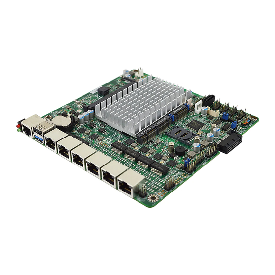
MI05 Series
User's Manual
NO. G03-MI05-F
Revision: 2.0
Release date: August 03, 2022
Trademark:
* Specifications and Information contained in this documentation are furnished for information use only, and are
subject to change at any time without notice, and should not be construed as a commitment by manufacturer.
Advertisement
Table of Contents

Related Manuals for JETWAY MI05 Series


Summary of Contents for JETWAY MI05 Series
- Page 1 MI05 Series User’s Manual NO. G03-MI05-F Revision: 2.0 Release date: August 03, 2022 Trademark: * Specifications and Information contained in this documentation are furnished for information use only, and are subject to change at any time without notice, and should not be construed as a commitment by manufacturer.
- Page 2 Environmental Protection Announcement Do not dispose this electronic device into the trash while discarding. To minimize pollution and ensure environment protection of mother earth, please recycle.
-
Page 3: Table Of Contents
TABLE OF CONTENT ENVIRONMENTAL SAFETY INSTRUCTION ............... iii USER’S NOTICE ........................iv MANUAL REVISION INFORMATION ................... iv ITEM CHECKLIST ........................ iv CHAPTER 1 INTRODUCTION OF THE MOTHERBOARD FEATURE OF MOTHERBOARD ................1 SPECIFICATION ....................2 LAYOUT DIAGRAM ....................3 CHAPTER 2 HARDWARE INSTALLATION JUMPER SETTING .................... -
Page 4: Environmental Safety Instruction
Environmental Safety Instruction Avoid the dusty, humidity and temperature extremes. Do not place the product in any area where it may become wet. 0 to 60 centigrade is the suitable temperature. (The figure comes from the request of the main chipset) ... -
Page 5: User's Notice
USER’S NOTICE COPYRIGHT OF THIS MANUAL BELONGS TO THE MANUFACTURER. NO PART OF THIS MANUAL, INCLUDING THE PRODUCTS AND SOFTWARE DESCRIBED IN IT MAY BE REPRODUCED, TRANSMITTED OR TRANSLATED INTO ANY LANGUAGE IN ANY FORM OR BY ANY MEANS WITHOUT WRITTEN PERMISSION OF THE MANUFACTURER. -
Page 6: Chapter 1 Introduction Of The Motherboard
Chapter 1 Introduction of the Motherboard 1-1 Feature of Motherboard Onboard Intel ® Elkhart Lake Series Processor, with low power consumption and high performance Support 1* DDR4 3200MHz SO-DIMM, up to 16GB Support 6* 10/100/1000/2500 Base-TX Ethernet Ports ... -
Page 7: Specification
1-2 Specification Spec Description Design Mini-ITX form factor 8 layers; PCB size: 17.0x17.0cm ® Intel Elkhart Lake series CPU (TDP 10W) Embedded CPU * for detailed CPU support information please visit our website 1* DDR4 SO-DIMM slot Memory Socket ... -
Page 8: Layout Diagram
1* HDMI port header 1* 8-pin LANLED header (LAN_LED1) 1* 4-pin LANLED header (LAN_LED2) 1* SMBUS header 1* GPIO port header 1* SIM Card Expansion Wafer 1-3 Layout Diagram Rear IO Diagram USB 2.0 Port RS232 RJ-45 Type COM 2.5Gbps RJ-45 Port for Console... - Page 9 Motherboard Internal Diagram Internal 12V FP_LED1 Header Power Connector BP_LED Port DDR4 SODIMM Slot RS232 RJ-45 Type COM Port : USB 2.0 Port Bottom: USB 3.1(Gen.2) Port CPUFAN Connector 2.5Gbps RJ-45 LAN Ports (LAN1/2/3/4/5/6) M.2 E-Key Slot (M2E1) HDMI Port Header SATA SATAIII Port Power-out...
- Page 10 Jumper Positions M2B_PWR M2M_PWR AT_MODE M2E_PWR JP80P JBAT...
- Page 11 Connectors Connector Name RJ45_COM1 RS232 RJ45 Type COM Port Connector for Console USB31 Top: USB 2.0 Port Connector Bottom: USB 3.1(Gen.2) Port Connector LAN1/2/3/4/5/6 2.5Gbps RJ-45 LAN Port Connector X6 SATA1 SATAIII Port Connector SATAPWR SATA Power out Connector CPUFAN CPUFAN Connector DCIN1 2-Pin Internal 12V DC–in Power Connector...
-
Page 12: Chapter 2 Hardware Installation
Jumpers Jumper Name Description Pitch JBAT Pin (1-2): Clear RTC Pin (3-4): Clear CMOS 8-Pin Block 2.54mm Pin (5-6): ME Disable Pin (7-8): CASE OPEN AT_MODE ATX Mode/ AT Mode Select 3-Pin Block 2.54mm JP80P Set GPIO_CON 2-Pin Block 2.54mm M2E_PWR M.2 E-key Power Select 3-Pin Block... - Page 13 Pin (3-4) of JBAT (8pin): Clear CMOS Pitch=2.54mm JBAT Pin (5-6) of JBAT (8pin): ME Disable Pitch=2.54mm JBAT...
- Page 14 Pin (7-8) of JBAT (8pin): CASE OPEN Pitch=2.54mm JBAT Pin (7-8) short: When Case open function pin short to GND, the Case open function was detected. When used, needs to enter BIOS and enable ‘Case Open Detect’ function. Refer to Page-31. In this case if your case is removed, next time when you restart your computer, a message will be displayed on screen to inform you of this.
- Page 15 JP80P (2-pin) :Set GPIO Pitch=2.54mm JP80P M2E_PWR (3-pin): M.2 E-key Power Select Pitch=2.54mm 1-2 Closed:VCC=VCC3 M2E_PWR 2-3 Closed: VCC=3VSB...
- Page 16 M2M_PWR (3-pin): M.2 M-key Power Select Pitch=2.54mm M2M_PWR M2B_PWR (3-pin): M.2 B-key Power Select Pitch=2.54mm M2B_PWR...
-
Page 17: Connectors, Headers And Wafers
Connectors, Headers and Wafers 2-2-1 Connectors (1) Rear I/O Connectors * Refer to Page-3 Rear IO Diagram. Icon Name Function Mainly for user to connect external MODEM RS232 RJ-45 Type COM Port or other devices that supports Serial Communications Interface. To connect USB keyboard, mouse or other USB 2.0 Port devices compatible with USB specification. - Page 18 (3) SATA1 (7-pin): SATAIII Port Connector SATA1 is a high-speed SATAIII port that supports 6Gb/s transfer rate. SATA1 (4) SATAPWR (4-pin): SATA Power Out Connector SATAPWR Warning: Make sure that Pin-1 of compatible SATA Power connector is inserted into corresponding Pin-1 of SATAPWR connector to avoid possible damage to the board and hard disk driver!
- Page 19 (5) CPUFAN (4-pin): CPU FAN Connector CPUFAN (6) DCIN1 (2-pin) : Internal 12V DC-in power connector DCIN1 Warning: Find Pin-1 position before connecting power cable to this 2-pin power connector WRONG INSTALLATION DIRECTION WILL DAMAGE THE BOARD!!
-
Page 20: Headers & Wafers
2-2-2 Headers & Wafers (1) PIN (1-2) of FP_LED1 (4-pin):Power LED Pitch=2.54mm FP_LED1 (2) PIN (3-4) of FP_LED1 (4-pin):HDD LED Pitch=2.54mm FP_LED1... - Page 21 (3) LAN_LED1 (8-pin): LAN1 & LAN2 & LAN3 & LAN4 Activity LED Header Pitch=2.54mm LAN_LED1 (4) LAN_LED2 (4-pin): LAN5 & LAN6 Activity LED Header Pitch=2.54mm Pin1 LAN_LED2...
- Page 22 (5) SMBUS (5-pin):SM BUS Header Pitch=2.54mm SMBUS (6) GPIO (10-pin):GPIO Header Pitch=2.54mm GPIO *Note: Please refer to Page-10 JP80P jumper setting for GPIO 80Port or GPIO Port function select...
- Page 23 (7) JW_FP (9-pin):Front Panel Header Pitch=2.54mm JW_FP (8) FP_COM2 (9-pin): Serial Port Header ( support RS232/422/485 ) FP_COM3 / FP_COM4 (9-pin): Serial Port Header ( support RS232 ) Pitch=2.54mm Pin 1 Pin NO. RS232 *RS422 *RS485 DATA- Pin 1 Pin 2 DATA+ FP_COM2 Pin 3...
- Page 24 (9) PS2KBMS (6-pin): PS/2 Keyboard & Mouse Header Pitch=2.54mm MS_DATA MS_CLK KB_CLK KB_DATA PS2KBMS Pin 1 (10) FP_USB21 (9-pin):USB 2.0 Port Header Pitch=2.54mm FP_USB21...
- Page 25 (11) SIM (6-pin): SIM Card Expansion Wafer Pitch=2.0mm *Note: The board provides internal SIM card slot, and provide SIM card header when user need to insert SIM card externally. Once use SIM card header, the internal SIM card slot will be disable. (12) HDMI1 (19-pin):HDMI Port Header Pitch=2.0mm...
-
Page 26: Maximum Voltage & Current Limit
2-2-3 Maximum Voltage & Current Limit Below is a list of maximum voltage & Current Limit specification for motherboard interface (including but not limited to slots, connectors, wafers and headers) for setup reference: Location Function Working Voltage Current Support 1.5A USB31 USB2.0/USB 3.1(Gen.2) SATAPWR... -
Page 27: Chapter 3 Introducing Bios
Chapter 3 Introducing BIOS Notice! The BIOS options in this manual are for reference only. Different configurations may lead to difference in BIOS screen and BIOS screens in manuals are usually the first BIOS version when the board is released and may be different from your purchased motherboard. Users are welcome to download the latest BIOS version form our official website. -
Page 28: Bios Menu Screen
BIOS Menu Screen The following diagram show a general BIOS menu screen: Menu Bar General Help Items Current Setting Value Menu Items Function Keys BIOS Menu Screen Function Keys In the above BIOS Setup main menu of, you can see several options. We will explain these options step by step in the following pages of this chapter, but let us first see a short description of the function keys you may use here:... -
Page 29: Getting Help
Press (left, right) to select screen; Press (up, down) to choose, in the main menu, the option you want to confirm or to modify. Press <Enter> to select. Press <+>/<–> keys when you want to modify the BIOS parameters for the active option. -
Page 30: Main Menu
Boot To change boot settings Save & Exit Save setting, loading and exit options. User can press the right or left arrow key on the keyboard to switch from menu bar. The selected one is highlighted. Main Menu Main menu screen includes some basic system information. Highlight the item and then use the <+>... -
Page 31: Advanced Menu
3-7 Advanced Menu CPU Configuration Press [Enter] to enable or disable ‘Security Device Support’. Configuration Boot Performance Mode Use this item to select the performance state that the BIOS will set starting from reset vector. The optional settings: [Max Battery]; [Max Non-Turbo Performance]; [Turbo Performance] Intel(R) SpeedStep(tm) - Page 32 Use this item to allow more than two frequency ranges to be supported. The optional settings: [Disabled]; [Enabled]. When set as [Enabled], the following sub-items shall appear: Turbo Mode Use this item to enable or disable processor turbo mode (requires EMTTM enabled too).
- Page 33 Power Limit and TDP Limit. If value is 0, BIOS will program TDP value Power Limit 1 Time Window Use this item to power Limit 1 Time Window value in seconds. The value may vary from 0 to 128. 0=default value (28 sec for Mobile and 8 sec for desktop). Defines time Window which TDP value should be maintained.
- Page 34 When set Intel(R) TCC Mode as [Disabled], user can make further settings in the following items: IO Fabric Low Latency Use this item to enabled or disable IO Fabric Low Latency. This will turn off some power management in the PCH IO fabrics. This option provides the most aggressive IO Fabric performance setting.
- Page 35 NOTE: Your computer will reboot during restart in order to change state of security device The optional settings: [None]; [TPM Clear]. ACPI Settings Press [Enter] to make settings for the following sub-item: ACPI Settings ACPI Sleep State Use this item to select the highest ACPI sleep state the system will enter when the suspend button is pressed.
- Page 36 Use this item to select an optimal settings for Super IO Device. Use this item to select an optimal setting for super IO device. The optional settings are: [Auto]; [IO=3F8h; IRQ=4]; [IO=2F8h; IRQ=3]; [IO=3E8h; IRQ=4]; [IO=2E8h; IRQ=3] for ‘Serial Port 2 Configuration’. Transmission Mode Select The optional settings are: [RS422];...
- Page 37 When set as [Enabled], the following sub-items shall appear: WatchDog Wake-up Timer Value User can select a value in the range of [10] to [4095] seconds when ‘WatchDog Wake-up Timer Unit’ set as [Sec]; or in the range of [1] to [4095] minutes when ‘WatchDog Wake-up Timer Unit’...
- Page 38 The optional settings: [7]; [8]. Parity A parity bit can be sent with the data bits to detect some transmission errors. The optional settings: [None]; [Even]; [Odd]; [Mark]; [Space]. [Even]: parity bit is 0 if the num of 1’s in the data bits is even; [Odd]: parity bit is 0 if num of 1’s in the data bits is odd;...
- Page 39 The optional settings: [VT100]; [Linux]; [XTERMR6]; [SCO]; [ESCN]; [VT400]. Serial Port for Out-of-Band Management/ Windows Emergency Management Services (EMS) Console Redirection EMS The optional settings: [Disabled]; [Enabled]. When set as [Enabled], the following sub-items shall appear: Console Redirection Settings The settings specify how the host computer and the remote computer (which the user is using) will exchange data.
- Page 40 The default setting is: [None]. *This item may or may not show up, depending on different configuration. Stop Bits The default setting is: [1]. *This item may or may not show up, depending on different configuration. PC Health Status Press [Enter] to view current hardware health status, set shutdown temperature, or make further settings in ‘Smart Fan Configuration’.
- Page 41 USB Mass Storage Driver Support The optional settings are: [Disabled]; [Enabled]. USB Hardware Delays and Time-outs: USB Transfer Time-out Use this item to set the time-out value for control, bulk, and interrupt transfers. The optional settings are: [1 sec]; [5 sec]; [10 sec]; [20 sec]. Device Reset Time-out Use this item to set USB mass storage device start unit command time-out.
- Page 42 option will not be created. PXE boot wait time Use this item to wait time in seconds to press ESC key to about the PXE boot. Use either +/- or numeric Keys to set the value. Media Detect Count Use this item to set number of times presence of media will be checked. The optional setting range is from [1] to [50].
-
Page 43: Chipset Menu
PCIe Wake-up from S3-S5 The optional settings: [Enabled]; [Disabled]. PTT Configuration Press [Enter] to make settings for the following sub-items: TPM Device Selection Use this item to selects TPM device:PTT or dTPM. PTT-Enables PTT IN SkuMgr dTPM- Disables PTT in SkuMgr. Warning! PTT/ dTPM will be disabled and all data saved on it will be lost The optional settings: [dTPM];... - Page 44 System Agent (SA) Configuration GTT Size Use this item to select the GTT Size. The optional settings: [2MB]; [4MB]; [8MB]. DVMT Pre-Allocated Use this item to select DVMT 5.0 Pre-Allocated (Fixed) Graphics Memory size used by the Internal Graphics Device. The optional settings: [0M];...
- Page 45 The optional settings: [Bypass]; [Passthrough]. SATA Configuration SATA Controller Use this item to enable or disable SATA device. The optional settings: [Disabled]; [Enabled]. When set as [Enabled], the following sub-items shall appear: SATA Mode Selection This item determines how SATA controller(s) operate. The optional settings: [AHCI].
-
Page 46: Security Menu
3-9 Security Menu Security menu allow users to change administrator password and user password settings. Administrator Password If there is no password present on system, please press [Enter] to create new administrator password. If password is present on system, please press [Enter] to verify old password then to clear/change password. - Page 47 Secure Boot Press [Enter] to make customized secure settings: System Mode Secure Boot Secure Boot feature is Active if Secure Boot is Enabled, Platform Key(PK) is enrolled and the System is in User mode. The mode change requires platform reset.
- Page 48 Use this item to force system into User Mode. Install factory default Secure Boot key databases. Reset To Setup Mode Use this item to delete all Secure Boot key databases from NVRAM. Export Secure Boot variables Use this item to copy NVRAM content of Secure Boot variables to files in a root folder on a file system device.
-
Page 49: Boot Menu
3-10 Boot Menu Setup Prompt Timeout Use this item to set number of seconds to wait for setup activation key. Bootup Numlock State Use this item to select keyboard numlock state. The optional settings are: [On]; [Off]. Quiet Boot The optional settings are: [Disabled]; [Enabled]. Boot Option Priorities... -
Page 50: Save & Exit Menu
3-11 Save & Exit Menu Save Changes and Reset This item allows user to reset the system after saving the changes. Discard Changes and Reset This item allows user to reset the system without saving any changes. Restore Defaults Use this item to restore /load default values for all the setup options. Save as User Defaults Use this item to save the changes done so far as user defaults.