Advertisement
Quick Links
Advertisement

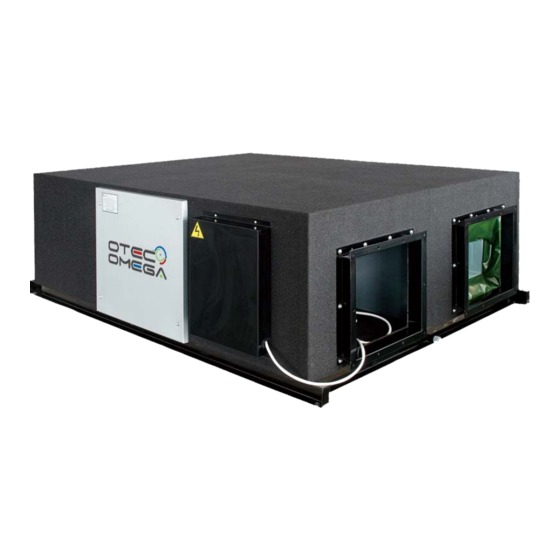
Summary of Contents for Omega OTEC ERVD Series
- Page 1 ERVD-ERVB Series Energy Recovery Ventilator Service Manual 220~240V/1/50Hz...
-
Page 2: Table Of Contents
Contents 1. Product Schedule ............2 2. External appearance ............2 3. Features ................2 4. Dimensions ..............4 5. Troubleshooting ............7 6. Maintenance ..............9 7. Controller ..............10 8. Accessory ..............12... -
Page 3: Product Schedule
1. Product Schedule Air volume dimension Net weight Model Power supply (L×W×H) (unit: mm) (kg) ERVD010A3N-DCN020 866×655×264 220V-1Ph-50Hz ERVD015A3N-DCN030 944×722×270 220V-1Ph-50Hz ERVD020A3N-DCN040 944×927×270 220V-1Ph-50Hz ERVD030A3N-DCN050 1038×1026×270 220V-1Ph-50Hz ERVD050A3N-DCN080 1286×1006×388 220V-1Ph-50Hz ERVD060A3N-DCN100 1000 1286×1256×388 220V-1Ph-50Hz ERVB090A3N-DCN150 1500 1600×1270×540 380V-3Ph-50HZ ERVB120A3N-DCN200 2000 1650×1470×540 380V-3Ph-50HZ 2. -
Page 4: Dimensions
4. Dimensions ERVD010 ERVD015, ERVD020, ERVD030, ERVD050, ERVD060 Model ERVD015A3N Φ144 ERVD020A3N Φ144 ERVD030A3N Φ194 ERVD050A3N Φ242 1116 1045 ERVD060A3N Φ242 1116 1045 1134 1190... - Page 5 ERVB090A3N-DCN150 ERVB120A3N-DCN200...
- Page 6 5. Maintenance Spaces...
-
Page 7: Troubleshooting
6. Troubleshooting 6.1 Lamp flashes Operation lamp Timerlamp Defrosting lamp Alarmlamp Explanation ★ ○ ○ ○ T4 sensor error ★ ★ ○ ○ T1 sensor error ★ ○ ★ Current protection ★ ○ ○ ★ Phase absent, phase error Note: ●:Light, ○:Extinguish, ☆:Slow flash, ★:Quick flash ERVD010, ERVD015, ERVD020, ERVD030, ERVD050, ERVD060 ERVB090, ERVB120 T1 temperature sensor: site at the return air cavity. - Page 8 6.2 Troubleshooting T4 sensor error / T1 sensor error Check whether the wiring of the temp. sensor is break off Connect the wiring well Check whether the resistance of temp. sensor is wrong refer Replace temp. sensor to the Annex 1 Replace main controller panel Current protection Turn off all motors, and...
-
Page 9: Maintenance
Phase absent, phase error Check: whether Lack of phase Connect it well. Check the connection between power supply and terminal, is the voltage in outdoor terminal is 3 phase. Check: whether Phase sequence error Change the order of two of the wires to power supply. Switch on the unit again. -
Page 10: Controller
8. Controller The basic operation conditions ofwired controller are as follows: 1. The range of power supply voltage: the voltage input is 5V DC. 2. Ambient temperature range: -15℃~+43℃. 3. Ambient humidity range: RH40%~RH90%. 4. The safety certification of electric control should conform to GB4706.32-2004, GB/T7725-2004. 17.1 Name and functions of buttons on wired controller 1 Mode selection button: It is used to select mode, push the button one time, then the operation modes will change in turn as follows:... - Page 11 9 Adjustment button: The button is only for time adjustment. Push the ▲ button, time increases. 10 Adjustment button: The button is only for time adjustment. Push the ▼ button, time decreases. 11 LOCK button (hidden): Use a small stick with the diameter of 1mm to push the LOCK button to lock the current setting, push the button again then cancel the setting.
-
Page 12: Accessory
9. Accessory Name Quantity shape Purpose Installation and owner’s manual must be delivered to the customer Butt-joint wire of wire control display panel For connect wire control and display control box (6 meters) HRV wire controller For controlling HRV units Annex 1 Characteristic of temperature sensor Resistance KΩ... - Page 13 OMEGA ERVD-ERVB Energy Recovery Ventilator Service Manua info@otecomega.com info@otecvrf.com www.otecomega.com www.otecvrf.com ERVDBA3N-SM1D0622...

