Cisco Firepower 1100 Series Hardware Installation Manual
Hide thumbs
Also See for Firepower 1100 Series:
- Hardware installation manual (30 pages) ,
- Installation manual (44 pages) ,
- Hardware installation manual (42 pages)
Table of Contents
Advertisement
Quick Links
Advertisement
Table of Contents

Related Manuals for Cisco Firepower 1100 Series


Summary of Contents for Cisco Firepower 1100 Series
- Page 1 Cisco Firepower 1100 Series Hardware Installation Guide First Published: 2019-06-13 Last Modified: 2022-07-27 Americas Headquarters Cisco Systems, Inc. 170 West Tasman Drive San Jose, CA 95134-1706 http://www.cisco.com Tel: 408 526-4000 800 553-NETS (6387) Fax: 408 527-0883...
- Page 2 Cisco and the Cisco logo are trademarks or registered trademarks of Cisco and/or its affiliates in the U.S. and other countries. To view a list of Cisco trademarks, go to this URL: https://www.cisco.com/c/en/us/about/legal/trademarks.html.
-
Page 3: Table Of Contents
Maintain Safety with Electricity Prevent ESD Damage Site Environment Site Considerations Power Supply Considerations Rack Configuration Considerations C H A P T E R 3 Rack-Mount the Chassis Unpack and Inspect the Chassis Rack-Mount the Chassis Cisco Firepower 1100 Series Hardware Installation Guide... - Page 4 Connect to the Console Port with Mac OS X Connect to the Console Port with Linux C H A P T E R 5 Installation, Maintenance, and Upgrade Replace the SSD Install the FIPS Opacity Shield in a Two-Post Rack Cisco Firepower 1100 Series Hardware Installation Guide...
-
Page 5: Overview
Power Cord Specifications, on page 12 Features The Cisco Firepower 1100 security appliances are a standalone modular security services platform. They are capable of running multiple security services simultaneously and so are targeted at the data center as a multiservice platform. See... - Page 6 Rear panel to front panel (cold aisle to hot aisle) One 16-core Intel CPU Processor One 12-core Intel CPU Memory 16-GB DDR4 DRAM 32-GB DDR4 DRAM Management port One Gigabit Ethernet RJ-45 10/100/1000 BaseT Restricted to network management access only Cisco Firepower 1100 Series Hardware Installation Guide...
- Page 7 • SFP-10G-LR • GLC-EX-SMD • SFP-10G-ER • GLC-ZX-SMD • SFP-10G-SR-S • GLC-T/TE • SFP-10G-LR-S • SFP-10G-ZR-S The SPFs are hot-swappable. • SFP-10G-ER-S • SFP-H10GB-CU 1M/1-5M/2M/ 2-5M/3M/5M • SFP-H10GB-ACU 7M/10M • SFP-10G-AOC 1M/2M/3M/ 5M/7M/10M Cisco Firepower 1100 Series Hardware Installation Guide...
- Page 8 • RJ-45 (8P8C) port—Supports RS-232 signaling to an internal UART controller. The RJ-45 console port does not support a remote dial-in modem. You can use a standard management cable (Cisco part number 72-3383-01) to convert the RJ45-to-DB9 connection if necessary.
-
Page 9: Package Contents
Overview Package Contents Note For Windows operating systems, you must install a Cisco Windows USB Console Driver on any PC connected to the console port before using the USB console port. See Connect to the Console Port with Microsoft Windows, on page 29 for information on installing the driver. -
Page 10: Qr Code Sticker
The QR code sticker on the rear panel of the chassis points to the Firepower Easy Deployment Guide for Cisco Firepower 1000 or 2100 Firewalls that explains low touch provisioning (LTP). LTP allows anyone to Cisco Firepower 1100 Series Hardware Installation Guide... -
Page 11: Serial Number Location
— Serial Number Location You can view the serial number and additional model information on the compliance label located on the bottom of the chassis. The following figure shows a sample compliance label. Cisco Firepower 1100 Series Hardware Installation Guide... -
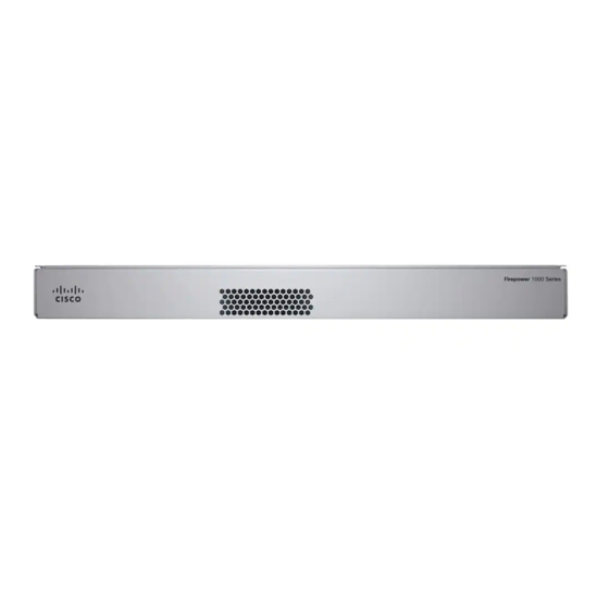
Page 12: Front Panel
The following figure shows the rear panel of the Firepower 1100. See Rear Panel LEDs, on page 9 for a description of the LEDs. See Features, on page 1 for a description of each feature. Figure 7: Firepower 1100 Rear Panel Cisco Firepower 1100 Series Hardware Installation Guide... -
Page 13: Rear Panel Leds
• Green, flashing—One flash every three seconds = 10 Mbps. • Green—Link established. • Green, flashing—Two rapid flashes = 100 • Green, flashing—Link activity. Mbps. • Green, flashing—Three rapid flashes = 1000 Mbps. Cisco Firepower 1100 Series Hardware Installation Guide... - Page 14 • Green and amber, flashing—Cloud connection failure. • Green—Cloud disconnected. Note The CDO LED pattern applies to low touch provisioning (LTP). See the Firepower Easy Deployment Guide for Cisco Firepower 1000 or 2100 Firewalls for more information. Cisco Firepower 1100 Series Hardware Installation Guide...
-
Page 15: Hardware Specifications
If any internal components fail, you must get a return material authorization (RMA) for the entire chassis. See the Cisco Returns Portal for more information. Cisco Firepower 1100 Series Hardware Installation Guide... -
Page 16: Power Cord Specifications
Orders delivered to Argentina, Brazil, and Japan must have the appropriate power cord ordered with the system. Note Only the approved power cords or jumper power cords provided with the chassis are supported. The following power cords are supported. Cisco Firepower 1100 Series Hardware Installation Guide... - Page 17 Figure 10: Australia/New Zealand (CAB-ACA) Plug: AU10LS3 Cord set rating: 10 A, 250 V Connector: V1625 — Figure 11: Brazil (CAB-C13-ACB) Plug: NBR 14136 Cord set rating: 10 A, 250 V Connector: EL 701B (EN 60320/C13) — Cisco Firepower 1100 Series Hardware Installation Guide...
- Page 18 — Figure 13: Europe (CAB-ACE) Plug: M2511 Cord set rating: 16 A, 250 V Connector: V1625 — Figure 14: India (CAB-IND-10A) Plug: IA16A3-C Cord set rating: 16 A, 250 V Connector: V1625BS-E — Cisco Firepower 1100 Series Hardware Installation Guide...
- Page 19 — Figure 16: Japan (CAB-JPN-3PIN) Plug: M744 Cord set rating: 12 A, 125 V Connector: V1625 — Figure 17: Korea (CAB-AC-C13-KOR) Plug: M2511 Cord set rating: 10 A, 250 V Connector: V1625 — Cisco Firepower 1100 Series Hardware Installation Guide...
- Page 20 Figure 19: South Africa (AIR-PWR-CORD-SA) Plug: SA16A Cord set rating: 10 A, 250 V Connector: V1625 — Figure 20: Switzerland (CAB-ACS) Plug: SW10ZS3 Cord set rating: 10 A, 250 V Connector: V1625 — Cisco Firepower 1100 Series Hardware Installation Guide...
- Page 21 Cord set rating: 10 A, 125 V Connector: EL 701 (EN 60320/C13) — Figure 22: United Kingdom (CAB-ACU) Plug: 3P BS 1363 Cord set rating: 10 A, 250 V Connector: IEC 60320/C13 — Cisco Firepower 1100 Series Hardware Installation Guide...
- Page 22 Overview Power Cord Specifications Cisco Firepower 1100 Series Hardware Installation Guide...
-
Page 23: Installation Preparation
SAVE THESE INSTRUCTIONS Warning Statement 1004 Installation Instructions Read the installation instructions before using, installing, or connecting the system to the power source. Cisco Firepower 1100 Series Hardware Installation Guide... - Page 24 (EMI) that might disrupt other equipment, and they direct the flow of cooling air through the chassis. Do not operate the system unless all cards, faceplates, front covers, and rear covers are in place. Cisco Firepower 1100 Series Hardware Installation Guide...
-
Page 25: Safety Recommendations
Safety Recommendations Observe these safety guidelines: • Keep the area clear and dust free before, during, and after installation. • Keep tools away from walkways, where you and others might trip over them. Cisco Firepower 1100 Series Hardware Installation Guide... -
Page 26: Maintain Safety With Electricity
If no wrist strap is available, ground yourself by touching the metal part of the chassis. For safety, periodically check the resistance value of the antistatic strap, which should be between one and 10 megohms. Cisco Firepower 1100 Series Hardware Installation Guide... -
Page 27: Site Environment
• If you are using dual redundant (1+1) power supplies, we recommend that you use independent electrical circuits for each power supply. • Install an uninterruptible power source for your site, if possible. Cisco Firepower 1100 Series Hardware Installation Guide... -
Page 28: Rack Configuration Considerations
• Baffles can help to isolate exhaust air from intake air, which also helps to draw cooling air through the chassis. The best placement of the baffles depends on the airflow patterns in the rack. Experiment with different arrangements to position the baffles effectively. Cisco Firepower 1100 Series Hardware Installation Guide... -
Page 29: Rack-Mount The Chassis
We recommend you install the rack-mount brackets on the rear panel so that the chassis faces the hot aisle. See Package Contents, on page 5 for the rack-mount items in the accessory kit. Cisco Firepower 1100 Series Hardware Installation Guide... - Page 30 We recommend that you install the chassis with the I/O side (rear panel) facing the cold aisle. See the following illustration for an example of air flow from rear panel (cold aisle) to the front panel (hot aisle). Cisco Firepower 1100 Series Hardware Installation Guide...
- Page 31 Chassis non-I/O side (front panel) Air flow direction (I/O side to non-I/O side) — What to do next You can now install the cables and power cord, as described in the Cisco Firepower 1100 Getting Started Guide. Cisco Firepower 1100 Series Hardware Installation Guide...
- Page 32 Rack-Mount the Chassis Rack-Mount the Chassis Cisco Firepower 1100 Series Hardware Installation Guide...
-
Page 33: Connect To The Console Port
The drivers are OS-specific and not tied to the vendor of the console cable manufacturer. Step 2 Install the driver. Step 3 Connect a 5-pin USB Mini B to the console port as shown in the following figure. Cisco Firepower 1100 Series Hardware Installation Guide... - Page 34 To communicate with the chassis, start a terminal emulator application. This software should be configured with the following parameters: • 9600 baud • 8 data bits • no parity • 1 stop bit • no flow control Cisco Firepower 1100 Series Hardware Installation Guide...
-
Page 35: Connect To The Console Port With Mac Os X
Connect to the USB port with the following command followed by the chassis USB port speed Example: root@usb-suse /dev# screen /dev/ttyACM0 9600 Step 5 To disconnect the Linux USB console from the Terminal window, enter Ctrl-a followed by : then quit. Cisco Firepower 1100 Series Hardware Installation Guide... - Page 36 Connect to the Console Port Connect to the Console Port with Linux Cisco Firepower 1100 Series Hardware Installation Guide...
-
Page 37: Installation, Maintenance, And Upgrade
Loosen the thumb screws on both sides of the SSD bay and pull the existing SSD out of the bay. Step 2 Insert the new SSD into the bay and push it in until it is seated. Cisco Firepower 1100 Series Hardware Installation Guide... -
Page 38: Install The Fips Opacity Shield In A Two-Post Rack
Note Because the FIPS opacity shield covers the serial number on the chassis, the CO should copy the serial number and store it in a secure place. The serial number is needed when you call Cisco TAC. Before you begin Caution This procedure should be performed only by the Crypto Officer (CO). - Page 39 Do not remove the power cable until the power LED is off. After removing power from the chassis either by moving the power switch to OFF or unplugging the power cord, wait at least 10 seconds before turning power back ON. Cisco Firepower 1100 Series Hardware Installation Guide...
- Page 40 Attach seven of the TELs. See the figure below for the correct placement. Allow the TELs to cure for a minimum of 12 hours. Caution Any deviation in the placement of the TELs means the chassis is not in FIPS mode. Cisco Firepower 1100 Series Hardware Installation Guide...
- Page 41 Step 12 Place the chassis in FIPS mode. See the following procedures for how to place the chassis in FIPS mode: • ASA in Platform Mode • ASA in Appliance mode Cisco Firepower 1100 Series Hardware Installation Guide...
- Page 42 Installation, Maintenance, and Upgrade Install the FIPS Opacity Shield in a Two-Post Rack • FTD managed by FMC What to do next See the Cisco Firepower 1100 Getting Started Guide for further configuration information. Cisco Firepower 1100 Series Hardware Installation Guide...