Kenwood FG-273 Instruction Manual
Hide thumbs
Also See for FG-273:
- Instruction manual (15 pages) ,
- Service manual (12 pages) ,
- Service manual (14 pages)

Related Manuals for Kenwood FG-273


Summary of Contents for Kenwood FG-273
- Page 1 FUNCTION G E N E R A T O R FG-273 INSTRUCTION MANUAL K E N W O O D C O R P O R A T I O N ©PRINTED IN v...
-
Page 2: Table Of Contents
KENWOOD CORPORATION 1 7 - 5 , 2 - c h o m e , S h i b u y a , S h i b u y a - k u , T o k y o 150, J a p a n... -
Page 3: Introduction
INTRODUCTION The log sweep and linear sweep function provides The M O D E L F G - 2 7 3 Sweep/Function Generator sweep frequency control up to max. 1000 : 1. Sweep provides of a function generator, pulse generator, Sweep frequency is variable from 0.5 Hz (2 seconds) to 50 oscillator, and frequency counter. -
Page 4: Precautions
PRECAUTIONS Do not use the F G - 2 7 3 Function Generator under the Do not repeat switching on and off the Generator. f o l l o w i n g conditions : Places exposed to the direct sun light Follow the instructions in section "... -
Page 5: S P E C I F I C A T I O N S
S P E C I F I C A T I O N S < F R E Q U E N C Y CHARACTERISTICS > DC Offset • • • • • • ± 10V(open circuit) G E N E R A L ±... - Page 6 T T L OUTPUT < F R E Q U E N C Y COUNTER CHARACTERISTICS > R i s e / F a l l T i m e 25 ns or less Frequency Range • • • 5 Hz to 10 MHz (1Osec, 1 sec, Output T T L level 0.1 sec, &...
- Page 7 <SIZE & WEIGHT > <POWER SUPPLY > Dimensions ( W H D ) » • 2 4 0 x 64 x 190 mm Input Voltage • • • • * 1 0 0 / 1 2 0 / 2 2 0 / 2 4 0 V A C ± Weight 1.8 kg (Max.
-
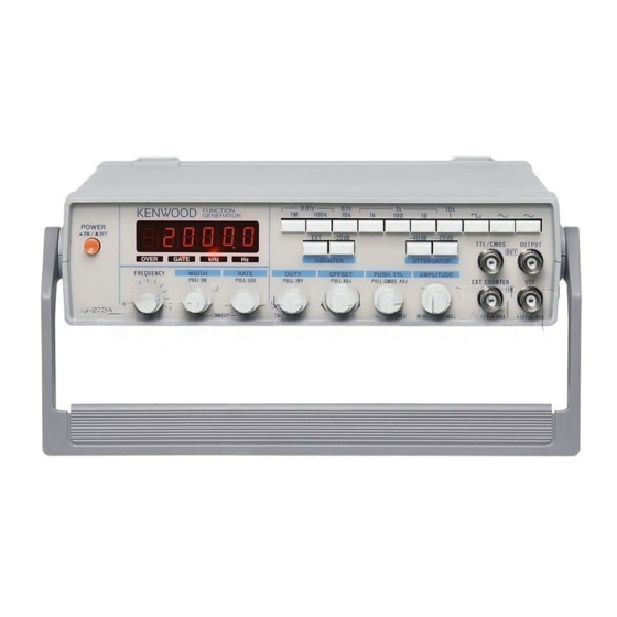
Page 8: O P E R A T O R ' S C O N T R O L S A N D I N S T R U T O N S
O P E R A T O R ' S CONTROLS AND INSTRUCTIONS FRONT PANEL Fig. 1... - Page 9 © S W E E P W I D T H / P U L L ON Control ® P O W E R Pushbutton Pulling the knob selects internal sweep. Rotating it Pressing this pushbutton turns on power. Counter controls sweep width.
- Page 10 © D U T Y / P U L L INV (Symmetry Adjustment/Polarity S e l e c t o r ) Knob Controls symmetry of output signal. Clockwise rotation varies the duty ratio from 1:1 to 4 0 : 1 . This adjustment makes pulse w a v e of square wave, ramp w a v e or s a w - t o o t h w a v e of triangle wave, and asymmetric sine wave of sine wave.
- Page 11 O F F S E T / P U L L A D J Control Pulling this knob admixes D C voltage with output signal. Clockwise rotation admixes positive voltage. Counterclockwise rotation admixes negative voltage- Fig. 3 iillustrates several types of waveform with the O F F S E T knob pulled and 5 0 - o h m load connected. Zero D C offset at max.
- Page 12 C O U N T E R - 2 0 dB Pushbutton- © PUSH T T L Knob ( C M O S Level Control K n o b ) Pressing the pushbutton attenuates counter input Pulling the control varies the level of C M O S square signal by 20'dB.
-
Page 13: Rear Panel
R E A R P A N E L Fig. 4 Power Connector Connector for supplying A C power. Use the dedicated power cord. © Fuse Holder Fuse holder for A C power supply. -
Page 14: Maintenance
MAINTENANCE Fuse Replacement If the fuse has blown out, find out and eliminate the cause. Then, replace it with a new fuse. Use a 0.3 A s l o w - b l o w fuse for supply voltage of 100 to 120 V , or a 0.2 A fuse for supply voltage of 220 to 240 V . - Page 15 Screws (4) Rubber shoe Case Fig. 5 Disassembly and Assembly of Case Fuse side Rear side Voltage selector plug Power transformer - Voltage terminal board Front side Fig. 6 Internal selection of Supply Voltage...