
Related Manuals for Kenwood FG-272


Summary of Contents for Kenwood FG-272
- Page 1 FUNCTION G E N E R A T O R FG-272 INSTRUCTION MANUAL K E N W O O D C O R P O R A T I O N ©PRINTED IN J .
-
Page 2: Table Of Contents
A p r o d u c t KENWOOD CORPORATION 17-5, 2 - c h o m e , S h i b u y a , S h i b u y a - k u , T o k y o 150, J a p a n... -
Page 3: Introduction
INTRODUCTION The M O D E L F G - 2 7 2 Sweep/Function Generator provides from 0.5 Hz ( 2 seconds) to 50 Hz (20 milliseconds). Sweep control is implemented by applying sweep signal functions of a function generator, pulse generator, and to the V C F connector from an external device. -
Page 4: Precautions
PRECAUTIONS Do not use the F G - 2 7 2 Function Generator under Do not repeat switching on and off the Generator, the following conditions : Places exposed to the direct sun light Follow the instructions in section " M A I N T E N A N C E Very hot and humid rooms if the supply voltage is to be changed. -
Page 5: S P E C I F I C A T I O N S
S P E C I F I C A T I O N S < F R E Q U E N C Y CHARACTERISTICS > SINE WAVE G E N E R A L Distortion Ratio 1% or less (10 Hz to 100 kHz) Output Frequency Response •... - Page 6 T T L OUTPUT < POWER SUPPLY > R i s e / F a l l Time 25 ns or less Input Voltage 100/120/220/240 V A C ± 10% (Max. 250V A C ) Output T T L level Frequency •...
- Page 7 <SIZE & WEIGHT > Dimensions ( W H O ) • 240 x 64 x 190 mm Weight 1.8 kg < ACCESSORIES > Instruction Manual • • • • • • • 1 A C cable • • • • • • • • • • • • 1 Fuse (0.3 A T ) ( 0 .
-
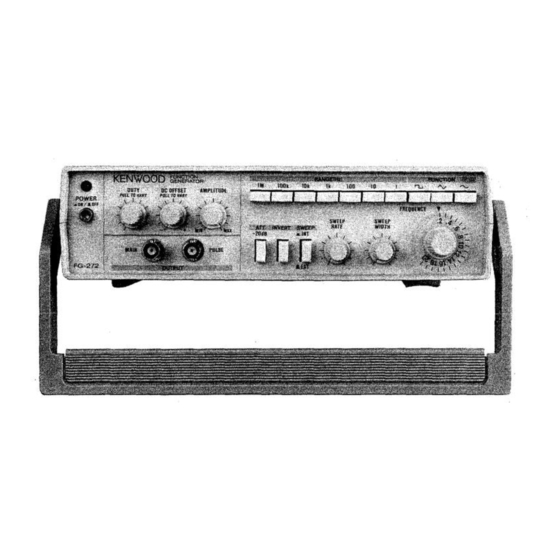
Page 8: O P E R A T O R ' S Controls And Instructions
O P E R A T O R ' S CONTROLS AND INSTRUCTIONS FRONT PANEL Fig. 1... - Page 9 ® P O W E R Pushbutton A T T - 2 0 dB Pushbutton Pressing this pushbutton turns on power. L E D lights pressing this pushbutton attenuates input signal by up to indicate power is on* 20 dB. ( 2 ) R A N G E ( H z ) Selector Switch Assembly Selects the following seven ranges of oscillation...
- Page 10 I N V E R T Pushbutton Depressing (button engaged) inverts polarity. Another press (button released) recovers the former polarity. Fig. 2 illustrates effects of the I N V E R T pushbutton with respect to D U T Y control knob setting. ^ \ ^ ^ F >...
- Page 11 © M A I N / P U L S E O U T P U T Jack DC O F F S E T Control MAIN : Outputs sine wave, triangl wave, or square Pulling this knob admixes DC voltage with output wave selected with the F U N C T T O N switch signal.
- Page 12 © S W E E P R A T E Control D U T Y / P U L L T O WARS (Symmetry Adjustment) Control Controls sweep rate (sweep frequency) of the internal Controls symmetry of output signal. sweep oscillator. Pulling this knob, and clockwise rotation varies the duty ratio from 1:1 to 5 : 1 .
-
Page 13: Rear Panel
REAR PANEL Fig. 4 © Power Connector © V C F Input Jack Connector for supplying A C power. By applying voltage to this jack in the state where Use the dedicated power cord. the S W E E P selector pushbutton © is another press (button released), frequency of output signal can ©... -
Page 14: Maintenance
MAINTENANCE Fuse Replacement If the fuse has blown out, find out and eliminate the cause. Then, replace it with a new fuse. Use a 0.3 A s l o w - b l o w fuse for supply voltage of 100 to 120 V , or a 0.2 A fuse for supply voltage of 220 to 240 V . - Page 15 Screws (4) Rubber shoe Case Fig. 5 Disassembly and Assembly of Case Fuse side Rear side Voltage selector plug Power transformer Voltage terminal board Front side Fig. 6 Internal Selection of Supply Voltage...