
Related Manuals for GE Multilin DGPR


Summary of Contents for GE Multilin DGPR
- Page 1 Grid Solutions Multilin DGPR Instruction Manual GE publication code: 1601-0410-A2 1601-0410-A2...
- Page 2 The contents of this manual are the property of GE Multilin. This documentation is furnished on license and may not be reproduced in whole or in part without the permission of GE Multilin. The content of this manual is for informational use only and is subject to change without notice.
-
Page 3: Table Of Contents
Connect wires ............................... 23 Activate G60 relay......................26 Install software......................26 Connect G60 relay......................26 Connect using RS232 port........................26 Connect using Ethernet port........................28 Connect using RS485 port........................28 IRIG-B..........................28 4 MAINTENANCE Repairs..........................29 A MISCELLANEOUS Warranty ........................31 MULTILIN DGPR – INSTRUCTION MANUAL... - Page 4 TABLE OF CONTENTS Revision history ......................31 INDEX MULTILIN DGPR – INSTRUCTION MANUAL...
-
Page 5: Introduction
650 Markland Street Markham, Ontario Canada L6C 0M1 Worldwide telephone: +1 905 927 7070 Europe/Middle East/Africa telephone: +34 94 485 88 54 North America toll-free: 1 800 547 8629 Fax: +1 905 927 5098 Worldwide e-mail: multilin.tech@ge.com MULTILIN DGPR – INSTRUCTION MANUAL... - Page 6 FOR FURTHER ASSISTANCE CHAPTER 1: INTRODUCTION Europe e-mail: multilin.tech.euro@ge.com Website: http://www.gegridsolutions.com/multilin MULTILIN DGPR – INSTRUCTION MANUAL...
-
Page 7: Product Product Description
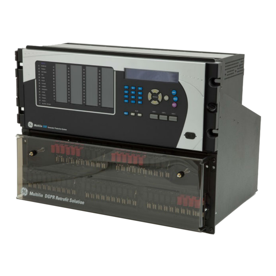
This chapter outlines the product, order codes, and specifications. Product description The Multilin DGPR is a retrofit solution for the Digital Generator Protection (DGP) Relay. The DGPR is a one-to-one replacement of a DGP relay and includes a G60 Generator Protection System, which is part of the GE Universal Relay (UR) series of products. - Page 8 DGP settings as installed, converted and installed on G60 (optional item) In addition to the DGP, the following devices and functionalities can be integrated in the DGPR unit as optional features: • Backup 21/78 (LPS-O) • 50RE • 50/62 BF MULTILIN DGPR – INSTRUCTION MANUAL...
-
Page 9: Specifications
Line Protection System (LPS-O) cover plate is included, while the GS1 options means that DGP settings are to be converted to the G60 settings. That is, GE converts DGP settings and uploads them to the G60. The LPS-O cover plate is mounted in the replacement of the LPS- O unit when it is removed from the panel. - Page 10 CHAPTER 2: PRODUCT DESCRIPTION CT MODULES WITH SENSITIVE GROUND APPROVALS Compliance Applicable council directive According to Low voltage directive EN 60255-5 EN 60255-27 EMC directive IEC 60255-26 IEC/TS 61000-6-5 C-UL-US UL 508 C22.2 No. 14-13 MULTILIN DGPR – INSTRUCTION MANUAL...
-
Page 11: Installation
Lift and place the unit on a bench in a standing position. Do not lay the unit on the back terminal blocks. Laying the unit on the back terminal blocks can break the insulators. Leave the installation tools inserted in the holes. They are required to mount the unit in the rack. MULTILIN DGPR – INSTRUCTION MANUAL... - Page 12 For further assistance section on page 1. Obtain the G60 instruction manual from https://www.gegridsolutions.com/multilin/manuals/index.htm The warranty is included at the end of this instruction manual and on the GE Grid Solutions website. Any updates to the DGPR instruction manual are at https://www.gegridsolutions.com/app/viewfiles.aspx?prod=pkgsol&type=3...
-
Page 13: Dimensions
The DGPR dimensions are 14" (height) × 19" (width) × 14" (depth). The following figures show the front, side, rear, and dimensions of the DGPR and G60. Figure 6: Front view and dimensions Figure 7: Right side view and dimensions MULTILIN DGPR – INSTRUCTION MANUAL... - Page 14 DIMENSIONS CHAPTER 3: INSTALLATION Figure 8: Rear view Figure 9: G60 rear view MULTILIN DGPR – INSTRUCTION MANUAL...
-
Page 15: Wiring
DGP and then connected to the same terminal blocks at the back of DGPR, except for the power supply alarm connections. See DGPR drawing GPRP000002 for details. Figures 11 and 12 show DGPR AC and DC schematics. MULTILIN DGPR – INSTRUCTION MANUAL... - Page 16 WIRING CHAPTER 3: INSTALLATION Figure 10: DGPR G60 wiring diagram (drawing GPRP000002) MULTILIN DGPR – INSTRUCTION MANUAL...
- Page 17 CHAPTER 3: INSTALLATION WIRING Figure 11: DGPR AC schematic (drawing GPRP000002) MULTILIN DGPR – INSTRUCTION MANUAL...
- Page 18 WIRING CHAPTER 3: INSTALLATION Figure 12: DGPR DC schematic (drawing GPRP000002) MULTILIN DGPR – INSTRUCTION MANUAL...
-
Page 19: Difference Between Ct Connections Of Dgp And Dgpr
On four-wire circuits, the fourth current transformer is connected in the neutral circuit, shown with a dotted line in the Figure 14. MULTILIN DGPR – INSTRUCTION MANUAL... -
Page 20: Ct Inputs System Side
CT (Figure 15), the GE application team can verify customer requirements and modify the default configuration of the DGPR. This type of connection is considered a custom order. -
Page 21: Ct Inputs Neutral Side
Vx are derived from the generator terminal voltage and generator neutral ground transformer, respectively. The jumpers for both VT connection types are labeled and provided with the DGPR unit. Verify the VT connection type and fix the jumpers accordingly. MULTILIN DGPR – INSTRUCTION MANUAL... -
Page 22: Digital Inputs And Outputs
DI4 - External Trip 2 (or GPMS Alarm: Option) • DI5 - Oscillography Trigger • DI6 - External VTFF • DI7 - Spare (or Ext. BF Trip: Option) • DI8 - Spare (or 81RE: Option) MULTILIN DGPR – INSTRUCTION MANUAL... -
Page 23: Outputs
DO16 — Alarm D (74D) • DO17 — VTFF (74FF) • DO18 — Spare (or 50/62 BF Trip: Option) • DO19 — Self-Test Non-Critical -Any Minor Failure (74NC) • DO20 — Self-Test Critical Failure (74CR) MULTILIN DGPR – INSTRUCTION MANUAL... -
Page 24: Test Switches
Figure 19: DGPR test switch configuration (drawing GPRP000002) Do not switch the test switches under load or similar conditions. Do not touch any open blade when the system is energized. Death or serious injury can result. MULTILIN DGPR – INSTRUCTION MANUAL... -
Page 25: Install Hardware
Lift the unit while each person holds one of the installation tools inserted in holes E or F with one hand and the bottom surface of the DGPR with the other hand. MULTILIN DGPR – INSTRUCTION MANUAL... - Page 26 Remove the installation tools, and install two screws in holes E and F. Apply two nuts in locations G and H. Install the two screws for the Lexan cover on the test switch faceplate, as shown in Figure 23. MULTILIN DGPR – INSTRUCTION MANUAL...
-
Page 27: Connect Wires
INSTALL HARDWARE Figure 23: Screw locations for Lexan cover Install the Lexan cover (GE part number 1502-0052), aligning the thumb nuts to the installed screws. 10. Hand-tighten the thumb nuts to secure the Lexan cover. Figure 24 shows the Lexan cover installed and tightened. - Page 28 DGPR, use one of these two options: – Two sources of power are available in the rack — Connect first power supply wires to AG1(+) and AG2(-) and second power supply wires to BG13(+) and BG14(-) as shown in Figure 27. MULTILIN DGPR – INSTRUCTION MANUAL...
- Page 29 Do not switch the test switches under load or similar conditions. Do not touch any open blade when the system is energized. Death or serious injury can result. MULTILIN DGPR – INSTRUCTION MANUAL...
-
Page 30: Activate G60 Relay
Connect using RS232 port The G60 has a nine-pin RS232 serial port on its front panel, as shown in Figure 29, which makes it useful for connecting the computer to the device in the field. MULTILIN DGPR – INSTRUCTION MANUAL... - Page 31 Figure 30 shows cabling for the RS232 port for both nine-pin and 25-pin connectors. The default baud rate for the RS232 port is 115200 bps, and this can be set to other values. Figure 30: RS232 port connections MULTILIN DGPR – INSTRUCTION MANUAL...
-
Page 32: Connect Using Ethernet Port
IRIG-B input, the G60 operates an internal oscillator with 1 µs resolution and accuracy. The GE MultiSync 100 1588 GPS Clock as well as third-party equipment are available for generating the IRIG-B signal; this equipment can use a global positioning system (GPS) satellite system to obtain the time reference so that devices at different geographic locations can be synchronized. -
Page 33: Maintenance
The process to return the device to the factory for repair is as follows: • Contact a GE Grid Solutions Technical Support Center as outlined in the For further assistance section on page 1. •... - Page 34 Customers are responsible for shipping costs to the factory, regardless of whether the unit is under warranty. • Fax a copy of the shipping information to the GE Grid Solutions service department in Canada at +1 905 927 5098. MULTILIN DGPR – INSTRUCTION MANUAL...
- Page 35 This chapter provides the warranty and revision history. Warranty For products shipped as of 1 October 2013, GE Grid Solutions warrants most of its GE manufactured products for 10 years. For warranty details including any limitations and disclaimers, see the Terms and Conditions at http://www.gegridsolutions.com/multilin/warranty.htm...
- Page 36 REVISION HISTORY APPENDIX A: MISCELLANEOUS MULTILIN DGPR – INSTRUCTION MANUAL...
- Page 37 CT input diagrams ................... 16 Customization .................... 16 Hardware installation ................21 Help, getting ....................1 Description .....................3 Devices, other ....................4 differences ....................15 disconnect ....................21 Inputs ......................18 Digital inputs and outputs ..............18 Dimensions .....................9 MULTILIN DGPR – INSTRUCTION MANUAL...
- Page 38 Power supply ....................24 Rack installation ..................21 Redundant power supply ............10, 24 Repair ....................1, 29, 31 Revision history of instruction manual ........31 RS232 port ....................26 RS485 port ....................28 Safety symbols ....................1 Serial number ....................7 Settings ......................5 MULTILIN DGPR – INSTRUCTION MANUAL...