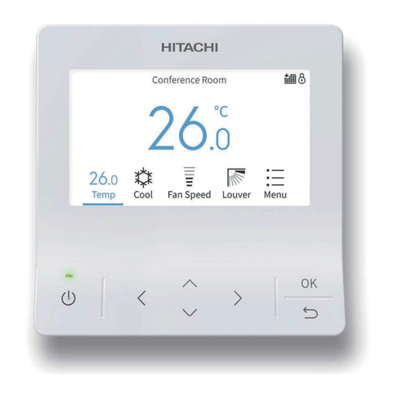
Hitachi PC-ARFG-E Installation & Operation Manual
Wired remote controller
Hide thumbs
Also See for PC-ARFG-E:
- Instruction manual (164 pages) ,
- Installation & operation manual (105 pages) ,
- Instruction manual (12 pages)
Table of Contents
Advertisement
Quick Links
–
INSTALLATION &
OPERATION
MANUAL
–
ADVANCED COLOR
WIRED REMOTE CONTROLLER
MODELS
PC-ARFG-E
EN
INSTALLATION AND OPERATION MANUAL
ES
MANUAL DE INSTALACIÓN Y FUNCIONAMIENTO
DE
INSTALLATIONS- UND BETRIEBSHANDBUCH
FR
MANUEL DʼINSTALLATION ET DE FONCTIONNEMENT
IT
MANUALE DI INSTALLAZIONE E DʼUSO
PT
MANUAL DE INSTALAÇÃO E FUNCIONAMENTO
DA
MONTERINGS- OG DRIFTSVEJLEDNING
NL
INSTALLATIE- EN BEDIENINGSHANDLEIDING
SV
INSTALLATION- OCH DRIFTHANDBOK
EL
ΕΓΧΕΙΡΙ∆ΙΟ ΕΓΚΑΤΑΣΤΑΣΗΣ ΚΑΙ ΛΕΙΤΟΥΡΓΙΑΣ
PMML0565 rev.1 - 04/2022
РЪКОВОДСТВО ЗА ИНСТАЛИРАНЕ И ЕКСПЛОАТАЦИЯ
BG
CS
NÁVOD K MONTÁŽI A OBSLUZE
HU
TELEPÍTÉSI ÉS ÜZEMELTETÉSI ÚTMUTATÓ
PL
INSTRUKCJA MONTAŻU I OBSŁUGI
RO
MANUAL DE INSTALARE SI OPERARE
ИНСТРУКЦИЯ ПО МОНТАЖУ И ЭКСПЛУАТАЦИИ
RU
FI
ASENNUS- JA KÄYTTÖOPPAASTAР
HR
PRIRUČNIKU ZA INSTALACIJU I UPOTREBU
SL
NAVODILA ZA MONTAŽO IN DELOVANJE
SK
NÁVOD NA PREVÁDZKU A INŠTALÁCIU
UK
ПОСІБНИКА З МОНТАЖУ ТА ЕКСПЛУАТАЦІЇ
Advertisement
Table of Contents

Related Manuals for Hitachi PC-ARFG-E


Summary of Contents for Hitachi PC-ARFG-E
- Page 1 INSTALLATION & OPERATION MANUAL – ADVANCED COLOR WIRED REMOTE CONTROLLER MODELS PC-ARFG-E INSTALLATION AND OPERATION MANUAL РЪКОВОДСТВО ЗА ИНСТАЛИРАНЕ И ЕКСПЛОАТАЦИЯ MANUAL DE INSTALACIÓN Y FUNCIONAMIENTO NÁVOD K MONTÁŽI A OBSLUZE INSTALLATIONS- UND BETRIEBSHANDBUCH TELEPÍTÉSI ÉS ÜZEMELTETÉSI ÚTMUTATÓ MANUEL DʼINSTALLATION ET DE FONCTIONNEMENT INSTRUKCJA MONTAŻU I OBSŁUGI...
- Page 3 Specifikationerna i den här handboken kan ändras utan föregående meddelande för att Hitachi ska kunna leverera de senaste innovationerna till kunderna. Vi på Hitachi gör allt vi kan för att se till att alla specifikationer stämmer, men vi har ingen kontroll över tryckfel och kan därför inte hållas ansvariga för den typen av fel.
- Page 4 Specifikacije u ovom priručniku podložne su izmjenama bez najave da bi tvrtka Hitachi mogla svojim klijentima pružiti najnovije inovacije. Iako se ulaže sav trud da bi se osigurala točnost svih specifikacija, greške u tisku nisu pod kontrolom tvrtke Hitachi; tvrtka Hitachi ne može biti odgovorna za takve greške.
- Page 5 C A U T I O N This product shall not be mixed with general house waste at the end of its life and it shall be retired according to the appropriated local or national regulations in a environmentally correct way. Due to the refrigerant, oil and other components contained in Air Conditioner, its dismantling must be done by a professional installer according to the applicable regulations.
- Page 6 В Н И М А Н И Е В края на своя технологичен живот този продукт не бива да се изхвърля заедно с общите битови отпадъци и трябва да се третира съгласно приетите местни или национални подзаконови нормативни актове по правилен от гледна точка на опазване на...
- Page 7 DANGER – Hazards or unsafe practices which COULD result in severe personal injuries or death. PELIGRO – Riesgos o prácticas poco seguras que PODRÍAN producir lesiones personales e incluso la muerte. GEFAHR – Gefährliche oder unsichere Anwendung, die zu schweren Körperverletzungen oder zum Tod führen kann. DANGER –...
- Page 8 ПРЕДУПРЕЖДЕНИЕ – Опасные или рискованные действия, которые МОГУТ привести к легким травмам или повреждению имущества. HUOMIO – Vaaralliset tai riskialttiit toimenpiteet, jotka SAATTAVAT aiheuttaa vähäisiä henkilövammoja tai tuotteen tai omaisuuden vahingoittumisen. OPREZ – Rizični ili nesigurni postupci koji MOGU uzrokovati lakše tjelesne ozljede ili oštećenje proizvoda ili vlasništva. POZOR - Nevarnosti in nevarna ravnanja LAHKO povzročijo manjše telesne poškodbe ali poškodbe izdelka ali materialno škodo.
- Page 9 English Original Version English Original Version Español Versión traducida Čeština Přeložená verze Deutsch Übersetzte Version Magyar Lefordított változat Français Version traduite Polski Tłumaczenie wersji oryginalnej Italiano Versione tradotta Română Versiune tradusă Português Versão traduzidal Русский Переведенная версия Dansk Oversat version Suomi Käännetty versio Nederlands...
-
Page 11: Table Of Contents
GENERAL INDEX General index 1 Safety summary ......................... 1 2 Switch Names and Functions ....................2 3 Operation ............................ 3 Operation Start/stop ............................. 3 Basic Operation ..............................3 Operation Mode..............................5 Temperature Setting ............................. 5 Fan Speed ................................6 LOUVER swing Direction ............................. 6 4 Icon Description......................... - Page 12 GENERAL INDEX 5.8.5 FloorSense cool air flow ............................... 22 Motion sensor setting ............................23 5.9.1 Motion sensor selection ..............................23 5.9.2 Absent setting selection ..............................24 5.9.3 Check interval time setting ............................24 5.10 Setback Setting ..............................25 5.10.1 Setback schedule setting ............................25 5.10.2 Setback manual setting ..............................
- Page 13 GENERAL INDEX 6.1.14 Cancel Preheating Control ............................67 6.1.15 Elevating grille Setting ..............................68 6.1.16 Power Up Setting ............................... 69 6.1.17 Setback Trigger Unit ..............................69 6.1.18 Refrigerant Leak Sensor Setting ..........................70 Service menu ..............................73 6.2.1 Operation Lock/Unlock Setting ............................. 73 6.2.2 Password Setting .................................
- Page 14 GENERAL INDEX 10 In Alarm Condition ....................... 101 10.1 Power Failure ..............................101 10.2 Electromagnetic Interference (EMI)........................101 PMML0565 rev.1 - 04/2022...
-
Page 15: Safety Summary
In case that the controller is installed in a place where there is electromagnetic wave radiation, If you have any questions, contact your Hitachi distributor or dealer. shield the controller and cables by covering with the steel box and running the cable through the metal conduit tube. -
Page 16: Switch Names And Functions
The complete information about the purchased products is supplied in a CD-ROM, which can be found bundled with the outdoor unit. In case that the CD-ROM is missing or it is not readable, please contact your Hitachi dealer or distributor. -
Page 17: Operation
OPERATION 3 OPERATION 3.1 OPERATION START/STOP Press “ ” (run/stop). The run indicator will be turned on/off and the operation will be started or stopped accordingly. N O T E • Once the temperature and air volume settings are entered on the wired controller, they are applied to the units. - Page 18 OPERATION Fan Speed Mode Menu Fan Speed 3 Air Conditioner ON Louver When air conditioner is on, press “ ” or “ ” to switch below items: “Temperature” ↔ “Mode” ↔ “Fan Speed” ↔ “Louver” ↔ “Menu”. Temperature Menu PMML0565 rev.1 - 04/2022...
-
Page 19: Operation Mode
OPERATION 3.3 OPERATION MODE Heating mode is only available when the indoor unit supports cooling and heating. Cooling only machine cannot support heating. Operation mode setting 1 Press “ ” or “ ” to select “Mode”. 2 Set the operation mode with “ ”... -
Page 20: Fan Speed
OPERATION 3.5 FAN SPEED 1 Press “ ” or “ to select “Fan Speed”. 2 By pressing “ ” or “ ”, the fan speed changes as follows. N O T E • During dry operation, the fan speed is automatically changed to “LOW”... -
Page 21: Icon Description
ICON DESCRIPTION 4 ICON DESCRIPTION The status of the remote controller is displayed on the operation screen. N O T E • It may not be displayed depending on the type of outdoor unit or indoor unit you are using. •... - Page 22 ICON DESCRIPTION Icon Description Power savings Power savings: Low Either the outdoor capacity control, indoor rotation control, or intermittent operation control is set. Power Savings: Med Power savings: High Outdoor capacity control is set on the central controller or outdoor unit. External saving It does not light when the indoor rotation control or intermittent operation control of the remote controller is set.
-
Page 23: Function Menu
FUNCTION MENU 5 FUNCTION MENU N O T E • Some functions cannot be set depending on the type, configuration, and usage status of the indoor unit. • If a function with " " is displayed, it means the function is not supported and the setting is disabled. -
Page 24: Operation Schedule Setting
FUNCTION MENU 3 Press “ ” or “ ” to set each setting data for the selected • When “ON Time” or “OFF Time” is selected, the setting time items. can be adjusted in 30-minute increments by pressing “ ” or After setting, press “... -
Page 25: Schedule Day And Time Setting
FUNCTION MENU 5.2.1 Schedule Day and Time Setting N O T E 4 Press” ” or “ ” to select schedule timer No.1 to No.5, and press “ ” or “ ” to select “ON Time” ↔ “OFF Time” ↔ •... -
Page 26: Schedule Turn On/Off Setting
FUNCTION MENU 5.2.2 Schedule Turn ON/OFF Setting 5.2.3 Schedule Holiday Setting 1 Select “Operation Schedule” on the “Function Menu” screen N O T E and press “OK”. For holiday setting, the schedule setting indicator turns off. • If the current time is not set, the “Adjusting Date/Time” setting screen is displayed. -
Page 27: Reset The Setting
FUNCTION MENU 5.2.4 Reset the setting 1 Select “Operation Schedule” on the “Function Menu” screen 3 Select "Yes" by pressing “ ” or “ ”and then press "OK". and press “OK”. All schedule and holiday settings are reset and the screen returns to the Step 3 of “5.2.1 Schedule Day and Time •... -
Page 28: Power Savings Mode Setting
FUNCTION MENU 5.3.1 Power Savings Mode Setting 5.3.2 Power Savings ON/OFF Setting 1 Select “Power Savings Setting” on the “Function Menu” 1 Select “Power Savings Setting” on the “Function Menu” screen and press “OK”. screen and press “OK”. 2 Press “ ” or “ ” to select the “ON/OFF”and press “OK”. 2 Press “... -
Page 29: Power Savings Level Setting
FUNCTION MENU 5.3.3 Power Savings Level Setting 3 Press “ ” or “ ”, the power savings level changes as follows: “LOW” ↔ “MED” ↔ “HIGH”. 1 Select “Power Savings Setting” on the “Function Menu” Select the level and press “OK”. screen and press “OK”. -
Page 30: Power Saving/Night Quiet Schedule Setting
FUNCTION MENU 2 Press “ ” or “ ”, the level changes as follows: “Not Set” ↔ “LOW” ↔ “MED” ↔ “HIGH”. Select the level and press “OK”. Press “ ”, the screen returns to the “Function Menu” screen. 5.5 POWER SAVING/NIGHT QUIET SCHEDULE SETTING Example of power saving operation and schedule This function starts and stops power savings control and setting... -
Page 31: Schedule Day And Time Setting
FUNCTION MENU 5.5.1 Schedule Day and Time Setting N O T E 4 Select the day of the week (from Mon. to Sun.) to be set with “ ” or “ ”, and press “OK”. indicates that schedule control is not possible. Refer to “7.1 Adjusting •... -
Page 32: Schedule Turn On/Off Setting
FUNCTION MENU 5.5.2 Schedule Turn ON/OFF Setting 1 Select “Power Saving/Night Quiet Schedule” on the 3 Press “ ” or “ ” to select “Turn ON/OFF Schedule, and then “Function Menu” screen and press “OK”. press “OK”. • If the sub remote controller or indoor unit does not support •... -
Page 33: Power Consumption Display
FUNCTION MENU 5.6 POWER CONSUMPTION DISPLAY This function displays the power consumption of the outdoor unit 3 Press “ ” or “ ” to select the display period, and then press compressor. “OK”. It switches in the order of 1 day (24 hours) ↔ 1 week The value of each displayed in Graph/List format is 1 day (7 days) ↔... -
Page 34: Autoboost (Quick Mode) Setting
FUNCTION MENU 5.7 AUTOBOOST (QUICK MODE) SETTING AUTOBOOST is the commercial name of the “Quick mode” 2 Press “ ” or “ ” the selected items changes as follows: function. “Not Set” ↔ “COOL” ↔ “HEAT” ↔ “Cool + Heat”. This function increases the cooling or the heating capacity for Select the Autoboost mode and press “OK”... -
Page 35: Comfort Setting
FUNCTION MENU 5.8 COMFORT SETTING 1 In order to access the Comfort settings menu, select N O T E “Comfort Setting” on the “Function Menu” screen and press • This function cannot be set when the indoor unit does not support “OK”. -
Page 36: Radiant Sensor Control For Heating
FUNCTION MENU 5.8.3 Radiant sensor control for heating The radiant sensor detects the radiation temperature of humans or objects by measuring the level of infrared light they emit. 1 Once in the Comfort setting menu, press “ ” or “ ” to select “Radiant Sensor Control for Heating”, and then press “OK”. -
Page 37: Motion Sensor Setting
FUNCTION MENU 5.9 MOTION SENSOR SETTING 5.9.1 Motion sensor selection This function and its settings are available only for indoor units equipped with a motion sensor. The motion sensor can 1 Select “Motion Sensor Setting” on the “Function Menu” be integrated into the front panel of the unit or a separate screen and press “OK”. -
Page 38: Absent Setting Selection
FUNCTION MENU 5.9.2 Absent setting selection The “If absent” setting defines the operation mode of the indoor 3 Press “ ” or “ ”, the operation changes as follows: units when “Auto-Save” function enters in the “If absent” control “ON” ↔ “Standby” ↔ “OFF” ↔ “Stop - Detect”. sequence. -
Page 39: Setback Setting
FUNCTION MENU 5.10 SETBACK SETTING 5.10.1 Setback schedule setting 2 Press “ ” or “ ” to select the settings, and the selected item changes as follows: Setback function is designed to maintain a minimum level of "ON Time" ↔ "OFF Time" ↔ “ ”. -
Page 40: Setback Manual Setting
FUNCTION MENU 5.10.2 Setback manual setting 2 Press “ ” or “ ” to select “ON”. Press “OK” and the screen returns to the “Function Menu” screen. This function is used to temporarily activate Setback operation. • The indicator turns on when schedule operation is ON. It is available only when Setback mode is set as Manual mode;... -
Page 41: Filter Reminder Reset Setting
FUNCTION MENU 3 Press " " to lower the grille until it's lowered to the set 4 After cleaning the air filter, install the air filter and press " " to distance. raise the grille. Once the grille is stored inside the unit, it will stop after approximately 3 seconds. -
Page 42: Frostwash
FUNCTION MENU 5.13 FROSTWASH 5.13.2 Start FrostWash FrostWash is available when applicable outdoor units and indoor units are connected. To use this function in VRF system, Generate frost on the coil and then melt the frost to wash the outdoor unit function selection item “F1” need to be configured coil. -
Page 43: Frostwash Setting On Outdoor Unit
FUNCTION MENU 5.13.3 FrostWash setting on outdoor unit To use this function in the VRF system, function selection F1 This function suppresses a clog on the heat exchanger. needs to be configured on the outdoor units. FrostWash setting First, freeze the indoor unit heat exchanger when whole system is disabled on the factory default setting. -
Page 44: Frostwash Setting
FUNCTION MENU 5.13.5 FrostWash Setting Manual FrostWash 1 In order to access FrostWash settings, select “FrostWash N O T E Setting” in Function Menu, and press “OK”. • The icon disappears when performing Manual FrostWash or when enabling the Auto-FrostWash. •... - Page 45 FUNCTION MENU Auto-FrostWash FrostWash Intervals 1 Press “ " or " " to select "Set FrostWash Intervals" and N O T E press "OK". The icon disappears when performing Manual FrostWash or when enabling Auto FrostWash. This function automatically starts FrostWash when the indoor unit operation is stopped and the set time interval has elapsed.
- Page 46 FUNCTION MENU Auto-FrostWash Schedule FrostWash Operation History 1 Press “ " or " " to select "Auto-FrostWash Schedule" and N O T E press "OK". • If the current time is not set, the date will be "- -". •...
-
Page 47: Display During Frostwash
FUNCTION MENU 5.13.6 Display during FrostWash During FrostWash operation, the following screens If the indoor or outdoor temperature does not sequences are displayed: meet the conditions for FrostWash, the following is displayed. - 1 When the indoor unit is out of the temperature ... -
Page 48: Individual Louver Setting
FUNCTION MENU 5.14 INDIVIDUAL LOUVER SETTING This function is to individually set the air direction of multiple air 3 Press” ”, “ ”, “ ”, or “ ” to select the indoor unit to change outlets. the louver direction, and press “OK”. N O T E N O T E •... -
Page 49: Cancel Individual Louver Setting
FUNCTION MENU 5.15 CANCEL INDIVIDUAL LOUVER SETTING 1 Select “Individual Louver Setting” on the “Function Menu” 3 Press” ”, “ ”, “ ”, or “ ” to select the indoor unit to cancel the and press “OK”. louver direction, and press “OK”. N O T E The indoor unit displayed on the screen flashes if an individual louver is set. -
Page 50: Ventilation
FUNCTION MENU 5.17 VENTILATION 2 Press “ " or " " to select the operation mode and press Operation Mode Action “OK” to confirm. The item changes as follows: “A/C” ↔ Operate the air conditioner individually. “Ventilation” ↔ “A/C + Ventilation”. Press "... -
Page 51: Night Purge
FUNCTION MENU 2 Press “ " or " " to select "Venti. Mode" and press "OK". 2 Press “ " or " " to select "Night Purge" and press "OK". 3 Press “ " or " " to select the operation mode and press “OK” 3 Press “... -
Page 52: Service & Installation Menu
SERVICE & INSTALLATION MENU 6 SERVICE & INSTALLATION MENU 1 While the air conditioner is OFF, press “ ” to select “Menu” 4 Input password by pressing “ ”, “ ”, “ ”, or “ ”, select “ ”. and press “OK”. Then press “OK”. -
Page 53: Installation Menu
SERVICE & INSTALLATION MENU 6.1 INSTALLATION MENU 6.1.1 Test Run 5 Cancel “Test Run” Mode When the unit is not in operation, press “ ”. 1 Select “Installation Menu” and press “OK”. When the unit is in operation, press “ ” (On/Off). 6.1.2 Function selection Function Selection is set from Installation Menu. - Page 54 SERVICE & INSTALLATION MENU 8 Select “Yes” and press”OK” to confirm the setting and return 4 Press “ ”, “ ”, “ ”, or “ ” to select the indoor unit to be set to Step 2. and press “OK”. Select “No”...
- Page 55 SERVICE & INSTALLATION MENU Table A. Optional Setting Items for Function Selection Individual Element Optional function Settings Setting conditions Description setting Normal (factory setting) This function is used to adjust (Setting Temperature + 4°C) the temperature difference between the temperature read No compensation by the inlet sensor and the real Heating temperature...
- Page 56 SERVICE & INSTALLATION MENU Individual Element Optional function Settings Setting conditions Description setting This function prevents the Function disabled (factory setting) modification of the fan speed Locking of fan speed setting of the unit from the remote (Not available for models controller and from central KPI-E4) controls, once it has been...
- Page 57 SERVICE & INSTALLATION MENU Individual Element Optional function Settings Setting conditions Description setting Function disabled (factory setting) Cancellation of forced This function is available compressor operation for at depending on the setting of Function enabled least 3 minutes function b3. (Compressor operation during 3 minutes is no longer forced) Sensor non enabled (factory setting)
- Page 58 Thermo-OFF conditions when conditions using the additional remote temperature sensor THM-R2AE N O T E (connected to THM4) or the PC-ARFG-E temperature For model RPI(L/H)-FSRE and Indoor unit fan is stopped during cooling sensor. RCD-FSR, this function is NOT Thermo-OFF C8 must be set to 01 to use the available.
- Page 59 SERVICE & INSTALLATION MENU Individual Element Optional function Settings Setting conditions Description setting Not used Use at 00 conditions This function prevents the Function disabled (factory setting) occurrence of an excessively cold air flow in heating mode Prevention of low air outlet by decreasing the fan speed temperature in heating mode during heating operation, also...
- Page 60 SERVICE & INSTALLATION MENU Individual Element Optional function Settings Setting conditions Description setting Disabled (factory setting) KPI: Pre-cooling / pre-heating This function delays unit startup 30 minutes period with energy recovery 60 minutes Disabled (factory setting) This function selects the CO Econofresh: CO sensor gas sensor input for Econofresh.
- Page 61 SERVICE & INSTALLATION MENU Individual Element Optional function Settings Setting conditions Description setting Control in “Automatic” indoor fan speed mode (supporting High H) Function disabled This function limits the speed Models: of the indoor fan when room RCI-FSR temperature is close to the RCIM-FSRE setting temperature, allowing to RCD-FSR...
- Page 62 SERVICE & INSTALLATION MENU Individual Element Optional function Settings Setting conditions Description setting 30 minutes (factory setting) 15 minutes This function sets the automatic Automatic reset time reset time delay for function F3. 60 minutes 90 minutes 19°C 20°C 21°C ·...
- Page 63 SERVICE & INSTALLATION MENU Individual Element Optional function Settings Setting conditions Description setting Function disabled 19°C is the standard minimum set point (factory setting) +1°C (Lower limit 20°C) +2°C (Lower limit 21°C) Lower limit of setting temperature for cooling This function defines the lowest +3°C (Lower limit 22°C) temperature setting value for (Minimum value of setting...
- Page 64 SERVICE & INSTALLATION MENU Individual Element Optional function Settings Setting conditions Description setting When there is a remote control Start/Stop allowed (Factory setting) prohibition from a central control device, this function overrides Start/Stop not allowed this prohibition allowing the Override of Start/Stop operation of the Run/Stop D A N G E R prohibition at the remote...
- Page 65 SERVICE & INSTALLATION MENU Individual Element Optional function Settings Setting conditions Description setting -0°C -0.5°C -1.0°C -1.5°C -2.0°C -2.5°C -3.0°C -3.5°C Calibration of remote Offset for the remote controller controller sensor sensor +0.5°C +1.0°C +1.5°C +2.0°C +2.5°C +3.0°C +3.5°C -0°C Not used Use at 00 conditions Not used...
- Page 66 SERVICE & INSTALLATION MENU Individual Element Optional function Settings Setting conditions Description setting Not used Use at 00 conditions Not used Use at 00 conditions Setting Position of Motion ○ Sensor Not used Use at 00 conditions Power save must be ON in Direct air blow Low (factory setting) order to use this function (L5 must be set to 01).
- Page 67 SERVICE & INSTALLATION MENU Individual Element Optional function Settings Setting conditions Description setting This function is used to define Enabled (0.5°C steps) whether setting temperature is (factory setting) adjusted in 0.5°C steps (when set to “00”) or in 1°C steps (when set to “01”).
- Page 68 SERVICE & INSTALLATION MENU Individual Element Optional function Settings Setting conditions Description setting Not used Use at 00 conditions Not used Use at 00 conditions Not used Use at 00 conditions Disabled Operation modes in which Cooling setback operation is activated to Operation mode with setback keep a minimum comfort in the Heating...
- Page 69 SERVICE & INSTALLATION MENU Individual Element Optional function Settings Setting conditions Description setting 0.5°C 1.0°C Setting of temperature 1.5°C This function can only be set differential for switching when function r1 is set to 01. 2.0°C cooling and heating 2.5°C 3.0°C Not used Not used...
- Page 70 SERVICE & INSTALLATION MENU Individual Element Optional function Settings Setting conditions Description setting Disabled 20.0°C 21.0°C 22.0°C If outdoor ambient temperature · · is higher than rC, there is no · · Maximum outdoor mode transition to heating · · temperature to allow in automatic cooling/heating operation mode switch to...
- Page 71 SERVICE & INSTALLATION MENU Individual Element Optional function Settings Setting conditions Description setting Not used Use at 00 conditions Not used Use at 00 conditions Not used Use at 00 conditions Not used Use at 00 conditions Not used Use at 00 conditions Not used Use at 00 conditions N O T E...
-
Page 72: Thermistor Selection
SERVICE & INSTALLATION MENU 6.1.3 Thermistor Selection This function is used to control the indoor temperature using 3 If “ ” or “ ” is pressed, the setting items are selected in the remote controller sensor instead of Inlet Air Thermistor in the following order: “IDU”... -
Page 73: Input / Output Setting
SERVICE & INSTALLATION MENU 6.1.4 Input / Output Setting 1 Select “Installation Menu” on the Service & Installation 4 Press “ ” or “ ” to select the item. screen and press “OK”. 5 Press “ ” or “ ” to change the setting. 2 Select “Input/Output”... - Page 74 SERVICE & INSTALLATION MENU Input and Output Number Display and Connectors Input Number Display Factory Setting Port Setting Input/Output Indication Setting Item Indication Input 1 CN3 1-2 Remote ON/OFF 1 (Level) Input 2 CN3 2-3 Prohibiting Remote Control after Manual Stoppage Output 1 CN7 1-2 Operation...
-
Page 75: Thermistor Calibration In Controller
SERVICE & INSTALLATION MENU 6.1.5 Thermistor Calibration in Controller 6.1.6 Fan Speed at Cooling Thermo-OFF This function is used to calibrate the temperature sensor This function is used to set the fan speed of the indoor unit at embedded into the wired remote controller Cooling Thermo-OFF. -
Page 76: Fan Speed At Heating Thermo-Off
SERVICE & INSTALLATION MENU 6.1.7 Fan Speed at Heating Thermo-OFF 6.1.8 Indoor Unit Address Change This function is used to set the fan speed of the indoor unit at This function is used to change the indoor unit address. Heating Thermo-OFF. N O T E 1 Select “Fan Speed at Heating Thermo-OFF”on the •... -
Page 77: Address Check Operation
SERVICE & INSTALLATION MENU 6.1.9 Address Check Operation 6 Press “ ” and select “Yes”. The address change processing starts. The result is displayed after a few seconds. This function allows the user to check the addresses of indoor units when several units are controlled from the same wired remote controller. -
Page 78: Address Initialization
SERVICE & INSTALLATION MENU 6.1.10 Address Initialization This function can be used to initialize the indoor units addresses, 3 Select “Yes” and press “OK”. The address initialization cancelling the settings done with the “Indoor Unit Address processing starts. Change” function. Using this function, the indoor units addresses will be restored as the addresses set physically on the indoor units PCB by DSW setting. -
Page 79: Setting Initialization
SERVICE & INSTALLATION MENU 6.1.11 Setting Initialization This function is used to restore the factory default settings of 4 Select “Complete” and press “OK”. To initialize another Function Selection and Input/Output. setting of Function Selection and Input/Output, select “Continue” and press “OK” to return to Step2. N O T E •... -
Page 80: Main Remote Setting
SERVICE & INSTALLATION MENU 6.1.12 Main Remote Setting Changing from the sub controller to the main controller If multiple remote control groups exist in the same outdoor 1 Select “Installation Menu” on the “Service & Installation” system, main/sub setting is automatically allocated. Set the screen by pressing “... -
Page 81: Priority Setting
• When using 2 remote controllers on the same indoor unit, it is not specialist or Hitachi Service team. possible to set priority • This function cannot be used in case that any of the following devices is connected to the same refrigerant cycle: - Outdoor unit or indoor unit not supporting power saving functions. -
Page 82: Elevating Grille Setting
SERVICE & INSTALLATION MENU 6.1.15 Elevating grille Setting In order to activate the elevating grille function for the related indoor units, some specific settings must be set for input/output contacts (refer to “Table A. Optional Setting Items for Function Selection” for details). -
Page 83: Power Up Setting
SERVICE & INSTALLATION MENU 6.1.17 Setback Trigger Unit 3 Select “Yes” and press “OK” to confirm the configuration. 4 When “Cancel” is selected, the screen returns to the The setback trigger unit can be set from the Installation Menu. “Elevating Grille Setting” menu. 1 Select the indoor unit by pressing “... -
Page 84: Refrigerant Leak Sensor Setting
SERVICE & INSTALLATION MENU 6.1.18 Refrigerant Leak Sensor Setting Test Run Function only available for those indoor units that are equipped 1 Select “Test Run” on the “Refrigerant Leak Sensor Setting” menu and press “OK”. with refrigerant leak sensor. Current European indoor units series are not equipped yet with this device, then the refrigerant leak sensor menu will have no action. - Page 85 SERVICE & INSTALLATION MENU Reset Leak Display Sensor ON Integration Time Reset 1 Select “Reset Sensor” on the “Refrigerant Leak Sensor 1 Select “Reset Sensor” on the “Refrigerant Leak Sensor Setting” menu and press “OK”. Setting” menu and press “OK”. 2 Select “Leak Display Reset”...
- Page 86 SERVICE & INSTALLATION MENU Check 1 4 Press “OK” to get pass the information screen. 1 Select “Check 1” on the “Refrigerant Leak Sensor Setting” menu and press “OK”. 5 A list of items will be displayed with the corresponding item description and its value.
-
Page 87: Service Menu
SERVICE & INSTALLATION MENU 6.2 SERVICE MENU 6.2.1 Operation Lock/Unlock Setting N O T E This function allows to lock one or several operation settings of the indoor unit from the remote controller. • Parameters F8, F9, F1 and FB must be set to 01 (available) in order to get the related setting available in the Lock Function menu. -
Page 88: Hotel Mode Setting
SERVICE & INSTALLATION MENU 6.2.3 Hotel Mode Setting 5 Press “ ” or “ ” to select “Save” and press “OK” to change password. This setting enables or disables the hotel mode. Select “Not Save”, the screen returns to Step3. Press “... - Page 89 SERVICE & INSTALLATION MENU Change the power savings level 1 Select “Service Menu” on the Service & Installation screen and press “OK”. Select “Sav: LOW (MED/HIGH)” and press “OK”. Press “ ” or 2 Select “Power Saving Details Setting” and press “OK”. “...
- Page 90 SERVICE & INSTALLATION MENU Indoor Unit Rotation Control Setting Change the Control Method • Select “Control” and press “OK”. Item Description • Press “ ” or “ ” to select the item to set and press “OK”. It changes as follows: “Address Order” ↔ “Temperature Order” Indoor units are set to Fan mode in Address ascending order, one by one, depending...
- Page 91 SERVICE & INSTALLATION MENU Intermittent Control Setting Cool/Dry Mode Heat Mode Normal Mode Item Description Power Normal Mode 20 minutes 25 minutes ⇔ Fan Saving: LOW ⇔ Fan Mode 10 minutes Level Change The power saving level can be set. Mode 5 minutes Normal Mode 1 Select “Service Menu”...
-
Page 92: Temperature Range Restriction
SERVICE & INSTALLATION MENU 6.2.5 Temperature Range Restriction 6.2.7 Main/Sub Display Setting The temperature range can be set by operating the remote The display of the main / sub setting of the remote controller can controller. be deactivated from this menu. 1 Select “Service Menu”... -
Page 93: Room Name Setting
SERVICE & INSTALLATION MENU 6.2.8 Room Name Setting 6.2.9 Contact Information Registration Register the installation location of the controller. Register a service contact (service address and service telephone number are recommended). 1 Select “Service Menu” on the “Service & Installation” screen and press “OK”. -
Page 94: Simple Maintenance
SERVICE & INSTALLATION MENU 6.2.10 Simple Maintenance List of Simple Maintenance Function This menu is available if the optional setting “JA” is set to 01 from the function selection menu. From this menu, some Item Note parameters like operating times and some items of the check mode can be displayed from the “Service Menu”. -
Page 95: Check Menu
SERVICE & INSTALLATION MENU 6.3 CHECK MENU This menu displays various statuses of the air conditioner. 2 Press “ ”, “ ”, “ ”, or “ ” to select the indoor unit. Press “OK”. If there is only one indoor unit connected to the wired remote 1 Select “Check Menu”... - Page 96 SERVICE & INSTALLATION MENU Checking the current operating condition Contents in Check 1 Temperature Status Display When Auto Cool/Heat is activated with the dual set point option, both Set Temp. temperature settings are displayed by “b1” parameter Temperature indication Normal Thermistor is disconnected Inlet air temperature...
- Page 97 SERVICE & INSTALLATION MENU Continue from previous page Stopping cause state indication Refer to “Cause of Indoor Unit Stoppage” Stopping cause state indication Continue to next page Cause of Stoppage Code Cause Operation OFF, Power OFF Thermo-OFF Alarm*1 Freeze Protection, Overheating Protection Instantaneous Power Failure at Outdoor Unit/Reset*2 Instantaneous Power Failure at Indoor Unit/Reset*3 Stoppage of Cooling Operation due to Low Outdoor Air Temp.
- Page 98 SERVICE & INSTALLATION MENU Continue from previous page Abnormality counter Times of abnormality Times of power failure This number is incremented when transmission error occurs between Times of abnormal transmitting Wired Remote Controller and Indoor units and the error remains for 3 (remote controller-outdoor unit) minutes or longer.
- Page 99 SERVICE & INSTALLATION MENU Continue from previous page Electronic Expansion Valve IDU Electronic Expansion Valve (%) ODU Electronic Expansion Valve (%) ODU Electronic Expansion Valve 2 (%) For flexible multi-type, the value of Unit A is indicated. ODU Electronic Expansion Valve B (%) Compressor status (reference) The total value is displayed if multiple compressors are operating.
- Page 100 SERVICE & INSTALLATION MENU Data just before the latest failure Contents of Check 2 Press “∨” to go to the next page. Press “∧” to go to the previous page. Continue from previous page Temperature Status Display Inlet Air Temperature Corresponds to item “b2”...
-
Page 101: Alarm History Display
SERVICE & INSTALLATION MENU 6.3.2 Alarm History Display 6.3.3 Model display function Alarm history can be browsed and deleted. Model type, unit type, and unit number are shown (this information is available only for compatible indoor units) 1 Select “Alarm History Display” on “Check Menu” and press “OK”. -
Page 102: Check Pcb Of The Units
SERVICE & INSTALLATION MENU 6.3.4 Check PCB of the Units Unit check result This function is used to Self check the PCB of the indoor and outdoor units. Indoor Unit PCB 1 Select “Check PCB of the Units” on the “Check Menu” Normal screen and press “OK”. -
Page 103: Self Check
SERVICE & INSTALLATION MENU 6.3.5 Self check Self check of the remote controller PCB can be performed. (Red) During the test, the internal memory of the controller (EEPROM) can be cleared and reset to factory settings. 1 Select “Self check” on the “Check Menu” screen and press “OK”. - Page 104 SERVICE & INSTALLATION MENU (Grey) 7 Buzzer check Press “ ” on Wired Remote Controller. Buzzer volume gradually increases. 06: Buzzer check 07: Transmission check 4 Back light check 03: Back light check 04: Run indicator check 8 Transmission check Wired Remote Controller then automatically starts transmission checking.
- Page 105 SERVICE & INSTALLATION MENU EEPROM process 11 Flash memory check Check flash memory. Ⓐ Ⓐ 1 Clear EEPROM N O T E Wired Remote Controller automatically starts EEPROM clear process. The checking process does not proceed to the next if “999” is shown in 2 After seconds, Wired Remote Controller automatically the area indicated with Ⓐ...
-
Page 106: Screen Display Setting Menu
SCREEN DISPLAY SETTING MENU 7 SCREEN DISPLAY SETTING MENU 1 Select “Screen Display Setting” on the “Menu” screen and press “OK”. Time and Date settings are recommended as this will be used by other functions like alarm history and timers. 2 Press “... -
Page 107: Time Format
SCREEN DISPLAY SETTING MENU 5 Press “ ”, or “ ” to select “yyyy/mm/dd/hh/mm”. 4 Press “ ” to return to Step2. Press “ ” or “ ” to change the settings. Press and hold “ ” or “ ” to increase or decrease continuously. -
Page 108: Run Indicator Brightness
SCREEN DISPLAY SETTING MENU 7.1.3 Run Indicator Brightness 7.1.4 Display Adjustment 1 Select “Run Indicator Brightness” on the “Screen Display Function Action Setting” screen and press “OK”. Backlight Brightness Adjust the brightness of the backlight. Change the time when the backlight turns dark Backlight Off Time after inactivity. -
Page 109: Temperature
SCREEN DISPLAY SETTING MENU 7.1.5 Temperature Backlight Off Time 1 Select “Display Adjustment” on the “Screen Display Setting” Function Action screen and press “OK”. Unit and Width Change temperature unit and width. Display of Thermistor Show/hide the thermistor temperature Temperature display on the home screen. -
Page 110: Language Setting
SCREEN DISPLAY SETTING MENU Display of Thermistor Temperature 1 Select “Language Setting” on the “Screen Display Setting” screen and press “OK”. 1 Select “Temperature” on the “Screen Display Setting” screen and press “OK”. 2 Press “ ” or " ” to select the language and press "OK". Press “... -
Page 111: Contact Information Menu
CONTACT INFORMATION MENU 8 CONTACT INFORMATION MENU The screen displays service contact information and the latest 2 Display service contact information and the latest alarm code. alarm code. Press" " to return to the "Menu" screen. 1 Select “Contact Information” from the “Menu” screen and press “OK”. - Page 112 HOTEL MODE SETTING Menu Louver • When the air conditioner is ON Press “ ” or “ ” to select the setting item. The item changes as follows: “Temperature” ↔ “Mode” ↔ “Fan Speed” ↔ “Louver” ↔ “Language” ↔ “Off Timer” ↔ “Menu”. Language Temperature Off timer...
-
Page 113: Language
HOTEL MODE SETTING Language: Change to the desired language. Off Timer: Turn off the air conditioner after the desired time. Screen Display Setting: Make settings for screen display. Please refer to “7 Screen Display Setting menu”. -
Page 114: Off Timer
HOTEL MODE SETTING 9.2 OFF TIMER N O T E 2 Press “ ” or “ ” to select the timer setting and press “OK”. • “ ” Off timer can be set even when the air conditioner is stopped. •... - Page 115 IN ALARM CONDITION 10 IN ALARM CONDITION Indoor unit number (Refrigerant system-address number) When more than one indoor unit is connected, press " " or " " to show other indoor units. Installed unit number • The RUN indicator flashes. •...
- Page 118 Johnson Controls-Hitachi Air Conditioning Spain, S.A.U. Ronda Shimizu, 1 - Políg. Ind. Can Torrella 08233 Vacarisses (Barcelona) Spain © Copyright 2022 Johnson Controls-Hitachi Air Conditioning Spain, S.A.U. – All rights reserved. PMML0565 rev.1 - 04/2022 Printed in Spain...