Advertisement
Quick Links
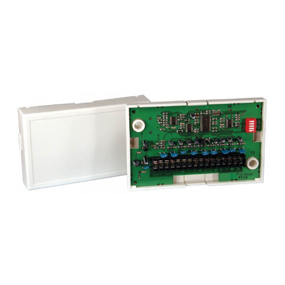
Installation manual
for the
DS7432 Eight Input Remote Module
1.0 Description
The DS7432 is an Eight Input Remote Module that provides a
means of addressing up to eight input loops of conventional
contacts to the multiplex bus of the control.
2.0 Specifications
•
Control Panel Requirements: The DS7432 is designed
to work with the following control panels:
•
A DS7400, DS7400X, DS7400Xi, DS7400Xi Rev. 3 or
DS7400Xi Rev. 4.
•
Up to 7 DS7432s can be used per DS7400 system.
•
Up to 15 DS7432 modules are allowed on DS7400X,
Xi and Xi Rev. 3.
•
The DS7400Xi Rev. 4 control panel can support up to
30 DS7432 modules.
•
One DS7430, DS7436 or DS9431 Multiplex Expansion
Module is required in the system to use the DS7432
Remote Module.
•
Current Draw: 10 mA Standby, 10 mA Alarm
•
Minimum Bus Voltage For Operation: 8 VDC peak
•
Wiring: Refer to the reference guide for the panel's
multiplex
expansion
requirements. The length of the wire connected to the loop
inputs on the DS7432 must be less than 250 ft. (76 m) per
loop.
•
The recommended wiring to the control is standard #18
(1.22 mm) or #22 (0.74 mm) AWG, quad (4-wire) cable.
Do not use shielded or twisted pair cable.
•
For fire applications, #18 AWG (1.2 mm) wire is
required.
3.0 Installation
P3 of the DS7432 is for European application
only. Do not put a jumper here.
P2 of the DS7432 allows the tamper switch to be bypassed
with a jumper when testing or servicing.
Remove jumper P2 when testing or servicing
has been completed.
Use the mounting holes (upper left and lower right corners) to
mount. It can be mounted inside or outside of the control
enclosure.
Route wiring as necessary from the DS7430, DS7436 or
DS9431 in the control enclosure and from the remote devices
to the DS7432.
Connect wiring as shown in Figure 3.
All manuals and user guides at all-guides.com
module
for
multiplex
wiring
If using separate powered detectors (other than
smoke
detectors)
Control/Communicator, the DS7432 can be
powered from the control panel auxiliary power
(terminals 7 and 8). The detector can be
connected to the DS7432 (see Figure 4). This
eliminates the need for home-run power wiring
from each detector to the control when the
DS7432 is mounted outside of the enclosure.
Be sure all wiring is unpowered before routing.
If the wiring is to enter through the rear of the enclosure, open
the DS7432's rear wire entrance. If the wiring is to run along
the surface of the enclosure, open the DS7432's surface wire
entrance. See Figure 2.
4.0 Programming
4.1 System Programming
Refer to the System Programming section in your panel's
reference guide for Zone programming information.
4.1 DIP Switch Settings
The DIP switches select which zones will be activated by the
loop inputs. Set the DIP switches as shown in Table 1 (Page
2).
•
No two DS7432s should be set the same.
•
The DS7432 occupies eight zones when connected to the
control panel. The input loops of the DS7432 correspond
to the zones of the control as shown in Table 2.
Figure 1: DIP Switch Orientation
+ – + – 1
2 3
POWER
BUS
Rear Wire Entrance
Figure 2: DS7432 Front View Without Cover
with
a
DS7400
Locking tab
P3
DIP switch
Tamper Switch
P2
4 5
6 7
8
Surface Wire Entrance
Series
Advertisement

Related Manuals for Bosch DS7432


Summary of Contents for Bosch DS7432
- Page 1 The length of the wire connected to the loop • No two DS7432s should be set the same. inputs on the DS7432 must be less than 250 ft. (76 m) per • The DS7432 occupies eight zones when connected to the loop.
- Page 2 Zones 241-248 201-208 Zones 249-256 209-216 217-224 able 2: Loop/Zone Number Relationship 225-232 233-240 241-248 Points 249-256 are not available for DS9400 249-256 use. Table 1: DIP Switch Settings DS7432 Installation manual © Bosch Security Systems B.V., 2020 Page 2...
- Page 3 Example: DS250 in an Smoke MB4W base. Detector Smoke Power - Smoke Detector Resistor P/N: 28010 Example: EOL200 Relay Figure 4: 4-Wire Smoke Detector Wiring for the DS7432 and DS7400Xi Control/Communicator. DS7432 Installation manual © Bosch Security Systems B.V., 2020 Page 3...
- Page 4 Only the BUS (+) needs to be connected. Figure 5: 4-Wire Smoke Detector Wiring for the DS7432 and DS9400 Series FACP For UL Listed fire installations, Normally Open (N/O) contacts must be used. © Bosch Security Systems B.V., 2020 2020.05...