Table of Contents
Advertisement
Quick Links
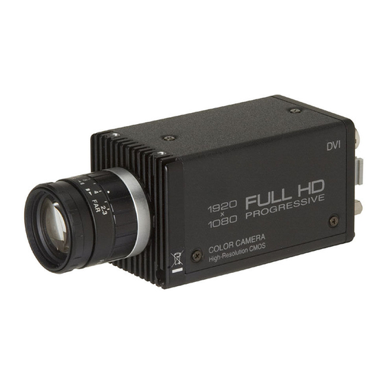
CMOS COLOR CAMERA
IK-HR2D
FCC NOTICE
This equipment has been tested and found to comply with the limits for a Class A digital device, pursu-
ant to Part 15 of the FCC Rules. These limits are designed to provide reasonable protection against
harmful interference when the equipment is operated in a commercial environment. This equipment
generates, uses, and can radiate radio frequency energy and, if not installed and used in accordance
with the instruction manual, may cause harmful interference to radio communications. Operation of this
equipment in a residential area is likely to cause harmful interference in which case the user will be
required to correct the interference at his own expense.
USER-INSTALLER CAUTION: Your authority to operate this FCC verified equipment could be voided if
you make changes or modifications not expressly approved by the party responsible for compliance to
Part 15 of the FCC Rules.
This Class A digital apparatus complies with Canadian ICES-003.
Cet appareil numérique de la classe A est comforme à la norme NMB-003 du Canada.
Following information is only for EU-member states:
In residential areas this product may cause radio interference, therefore this product must not be used
in residential areas.
Following information is only for EU-member states:
The use of the symbol indicates that this product may not be treated as household waste.
By ensuring this product is disposed of correctly, you will help prevent potential negative
consequences for the environment and human health, which could otherwise be caused by
inappropriate waste handling of this product. For more detailed information about the take-
back and recycling of this product, please contact your supplier where you purchased the
product or consult.
This manual is made from recycled paper.
INSTRUCTION MANUAL
For Customer Use
Enter the Serial # (which is
located on the bottom of the
cabinet) below. Retain this
information for future refer-
ence.
Model #
IK-HR2D
Serial #
Advertisement
Table of Contents

Related Manuals for Toshiba IK-HR2D


Summary of Contents for Toshiba IK-HR2D
- Page 1 CMOS COLOR CAMERA IK-HR2D FCC NOTICE This equipment has been tested and found to comply with the limits for a Class A digital device, pursu- ant to Part 15 of the FCC Rules. These limits are designed to provide reasonable protection against harmful interference when the equipment is operated in a commercial environment.
-
Page 2: Safety Precaution
SAFETY PRECAUTIONS Safety icons This manual contains safety instructions that must be observed in order to avoid potential hazards that could result in personal injuries, damage to your equipment, or loss of data. These safety cautions have been classified according to the seriousness of the risk, and the icons highlight these instructions as follows: Indicates a potentially hazardous situation which, if not avoided, could result in death or serious injury. -
Page 3: Disclaimer
5. Repairs or modifications made by the user or caused to be made by the user and carried out by an unauthorized third party. 6. Notwithstanding the foregoing, Toshiba’s liabilities shall not, in any circumstances, exceed the purchase price of the product. -
Page 4: Table Of Contents
Accordingly, [Toshiba/TAIS] disclaims any and all liability arising out of the use of the product in any critical applications. - Page 5 (3) WHT BAL (White Balance) ... (3.1) Changing the setting in AWB (Automatic White Balance) mode ... (3.2) Changing the setting in ATW (Automatic Tracking White balance) mode ... (3.3) Changing gain in MANUAL mode ... (4) PROCESS ... (4.1) Changing gamma correction ON/OFF ... (4.2) Changing gamma correction level...
-
Page 6: Cautions On Use And Installation
1. CAUTIONS ON USE AND INSTALLATION • Handling the unit. Do not drop, jolt, or vibrate, as this may result in damage to the unit. This may cause problems. Treat the camera cables carefully to prevent cable problems, such as breaks in the cable and loose connections. -
Page 7: Names And Functions
3. NAMES AND FUNCTIONS Prism faceplate [ Front ] [ Bottom ] Prism faceplate The protection cap is attached on the lens mount portion. After removing the cap, mount the lens. Be careful not to scratch or touch the optical area. DC IN 12V terminal Accepts a DC power input (12V). -
Page 8: Connection
Please use a DVI-D cable (commercially available) to connect this camera. * To display video with USB, use a computer which installs a USB 2.0 terminal and USB Video Class Driver. DVI terminal USB terminal IK-HR2D DC IN 12V DC power supply (option) Tri-pod adapter... -
Page 9: Connection On Rear Panel
* Recommended PC: S : Windows XP SP2 - SP3 ® Windows Vista ® Windows ® C P U : Intel Pentium compatible (x86 or x64) CPU ® ® 1 GHz or more. Memory : 512 MB or more * Please be aware that this camera will depend on the computer, environment, or cables and unless these are compatible, the camera may not operate correctly. -
Page 10: Operation
5 OPERATION Refer to the item "4. CONNECTION", and connect the equipment correctly. Turn on the connected equipment and the camera. Aim the lens at the object, adjust the lens iris adjustment, focus adjustment, etc. Refer to the item “5.1 White Balance”, make the adjustment. Please see “5.2 Gain”, “5.3 Switching video signal output”... - Page 11 Display Automatic white balance adjustment finished correctly. AWB OK Automatic white balance adjustment cannot be performed because the video level is AWB NG too low. LEVEL LOW Adjust the video level by increasing the illumination or opening the lens iris. Automatic white balance adjustment cannot be performed because the video level is AWB NG too high.
-
Page 12: Gain
5 2 Gain When the image is dark even if the lens iris is open, change the gain (video gain) to get the desired video level. For gain adjustment of the unit, MANUAL (Manual), OFF (0 dB) modes are provided. Select the mode on the GAIN menu. -
Page 13: Display Video With Usb
5 4 Display video with USB Connect a USB terminal of the camera and a USB terminal of the computer with a USB cable. Turn on the power of both the camera and the computer. Run the viewer software. * Please use a cable supporting mini-USB (B type) for the USB terminal of the camera. * To display video captured by the camera, viewer software supporting USB Video Class is required separately. -
Page 14: Items Controlled By The On Screen Display
6 ITEMS CONTROLLED BY THE ON SCREEN DISPLAY Item MODE AUTO, MANUAL, SS -100 AUTO level AUTO peak : average 00 10 AUTO response speed AUTO area PRESET A, PRESET B, PRESET C, PRESET D, PRESET E MANUAL speed OFF, 1/100s, 1/125s, 1/250s, 1/500s, 1/1000s, 1/2000s, 1/4000s Syncro. -
Page 15: Mode Setting By The On Screen Display
7 MODE SETTING BY THE ON SCREEN DISPLAY Various settings can be controlled on the unit by using the on screen menu displayed on the monitor. The contents once set are memorized in the scene files (A, B, C, D, E) selected, so if the power turns off, it is unnecessary to set the values again when using the unit next time. -
Page 16: Scene File
7 2 Scene File Five scene files (A, B, C, D, E) are available as user memories for this unit. These are chosen depending on shooting conditions. By pressing [DATA UP], [DATA DOWN] buttons while [DISP] button is pressed and the index menu is displayed, the camera operation is changed immediately from the currently selected scene file to the next. -
Page 17: (1.1) Changing The Setting In Auto Mode
1 1 Changing the setting in AUTO mode Move up and down Select the desired by pressing value by pressing MENU UP,DOWN DATA UP,DOWN -- 1 SHUTTER -- <FILE A> MODE LEVEL PEAK AVE SPEED AREA < MODE = AUTO> (a) Changing the video level in the automatic shutter mode Move the “... -
Page 18: (1.2) Changing The Setting In Manual Mode
(d) Changing the automatic shutter zone area Move the “ ” to AREA by pressing [MENU UP], [MENU DOWN] buttons. Select the measurement light area by pressing [DATA UP], [DATA DOWN] buttons. PRESET A PRESET B The available picture area is divided into 64 rectangles. The user can choose one of 5 presets. The shaded rectangles represents the area/pattern where the sampling is taken from. -
Page 19: (1.3) Changing The Setting In Ss (Synchro Scan) Mode
(a) Changing the shutter speed Move the “ ” to MANU by pressing [MENU UP], [MENU DOWN] buttons. Select the shutter speed by pressing [DATA UP], [DATA DOWN] buttons. 1/100s Note: The shutter speed can be set in every effective scanning line (1080/720). The figures of shutter speed in the menu screen are approximate. -
Page 20: Gain (Video Gain)
2 GAIN (Video gain) GAIN has two modes; MANUAL, OFF. Move the “ ” to MODE, press the [DATA UP], [DATA DOWN], and select one of the two modes : MANUAL, OFF. In the OFF mode, gain is fixed to 0dB. 2 1 Changing gain in MANUAL mode Move up and down Select the desired... - Page 21 (a) Changing R PAINT Move the “ ” to R PAINT by pressing [MENU UP], [MENU DOWN] buttons. Select the desired value of red paint by pressing [DATA UP], [DATA DOWN] buttons. - 10 Red is decreased. (b) Changing B PAINT Move the “...
-
Page 22: (3.2) Changing The Setting In Atw (Automatic Tracking White Balance) Mode
3 2 Changing the setting in ATW(Automatic Tracking White balance) mode Move up and down Select the desired by pressing value by pressing MENU UP,DOWN DATA UP,DOWN -- 3 WHT BAL -- <FILE A> MODE R PAINT B PAINT (a) Changing R PAINT Move the “... -
Page 23: (3.3) Changing Gain In Manual Mode
3 3 Changing gain in MANUAL mode Move up and down Select the desired by pressing value by pressing MENU UP,DOWN DATA UP,DOWN -- 3 WHT BAL -- <FILE A> MODE R GAIN B GAIN C TEMP (a) Changing the red gain Move the “... -
Page 24: Process
4 PROCESS Move up and down Select the desired by pressing value by pressing MENU UP,DOWN DATA UP,DOWN -- 4 PROCESS -- GAMMA ON/OFF GAMMA DTL GAIN DTL B.FREQ HIGH M PED 4 1 Changing gamma correction ON/OFF Move the “ ” to GAMMA ON/OFF by pressing [MENU UP], [MENU DOWN] buttons. Select either ON or OFF by pressing [DATA UP], [DATA DOWN] buttons. -
Page 25: (4.3) Changing Detail (Outline) Gain
4 3 Changing detail (outline) gain Move the “ ” to DTL GAIN by pressing [MENU UP], [MENU DOWN] buttons. Select the desired value of the detail gain by pressing [DATA UP], [DATA DOWN] buttons. The detail decreases. 4 4 Changing DTL B.FREQ (detail boost frequency) This setting adjusts the thickness of the image outline. -
Page 26: Matrix(Matrix Color Correction)
5 MATRIX(Matrix color correction) Red hue setting Red gain setting Green hue setting Green gain setting Blue hue setting Blue gain setting 5 1 Changing Matrix color correction ON/OFF Move the “ ” to MATRIX by pressing [MENU UP], [MENU DOWN] buttons. Select either ON or OFF by pressing [DATA UP], [DATA DOWN] buttons. -
Page 27: (6.1) Changing A Type Of Output Monitors
6 OPTION Select the desired value by pressing DATA UP,DOWN -- 6 OPTION MONITOR 6 1 Changing a type of output monitors Select either PC or TV by pressing [DATA UP], [DATA DOWN] buttons. PC: When using PC as an output monitor. TV: When using TV as an output monitor. -
Page 28: Before Making Service Call
8. BEFORE MAKING SERVICE CALL Symptom Is power supplied correctly? No picture Is the lens iris adjusted correctly? Are the camera and video cables connected correctly? Is the shutter mode set correctly? Does the video output from the camera match with the input signals from the monitor? Is the cable connector loose? Unstable picture... -
Page 29: External Appearance Diagram
10. EXTERNAL APPEARANCE DIAGRAM Unit : mm [inch] 2-M3 Depth 3 [0.118] 5 [0.2] 78 [3.07] 6.3 [0.25] 44 [1.73] 32.51[1.28] #4-40UNC [Front] [Rear] 56 [2.2] 5 [0.2] 4-M2 Depth 3 [0.118] 4-M3 Depth 3 [0.118] 25 [0.98] 25 [0.98]... - Page 30 Limited Warranty –TOSHIBA CMOS Color Camera The Imaging Systems Division of Toshiba America Information Systems, Inc. ("ISD") makes the following limited warranties with regard to this CMOS Color Camera ("Product"). These limited warranties extend to the Original End-User ("You[r]"). One (1) Year Limited Warranty of Labor and Parts ISD warrants that this Product will perform in accordance with specifications for a period of one (1) year from the date of purchase by the Original End-User.