Table of Contents
Advertisement
Quick Links
Advertisement
Table of Contents

Related Manuals for Samsung Smart MBS RRH-C2A

Summary of Contents for Samsung Smart MBS RRH-C2A
- Page 1 Ver. 2.0 Smart MBS RRH-C2A Installation Manual...
- Page 2 This manual is proprietary to SAMSUNG Electronics Co., Ltd. and is protected by copyright. No information contained herein may be copied, translated, transcribed or duplicated for any commercial purposes or disclosed to the third party in any form without the prior written consent of SAMSUNG Electronics Co., Ltd.
- Page 3 Smart MBS RRH-P4 Installation Manual INTRODUCTION Purpose This manual describes procedure and method for installing Smart MBS RRH-C2A. Document Content and Organization This manual consists of 2 Chapters, 6 Annex and Abbreviation as follows: CHAPTER 1. Before Installation This chapter introduces safety rules that must be understood for installing RRH-C2A and describes the configuration of RRH-C2A.
- Page 4 CHECKPOINT Provides the operator with checkpoints for stable system operation. NOTE Indicates additional information as a reference. Revision History EDITION DATE OF ISSUE REMARKS 10. 2011. First Edition © SAMSUNG Electronics Co., Ltd.
- Page 5 The purpose of the Safety Concerns section is to ensure the safety of users and prevent property damage. Please read this document carefully for proper use. Symbols Caution Indication of a general caution Restriction Indication for prohibiting an action for a product Instruction Indication for commanding a specifically required action © SAMSUNG Electronics Co., Ltd.
- Page 6 Wearing protection gloves and goggles Make sure to wear protection gloves and goggles to prevent damages from debris while drilling holes in a wall or ceiling. © SAMSUNG Electronics Co., Ltd.
- Page 7 When cutting the cable first, the length difference of cable end can be occurred by cable curvature and the power terminal may cause contact fault. © SAMSUNG Electronics Co., Ltd.
- Page 8 External Power Cable Support Bracket and two cable tie (stainless steel) for fixing cable are enclosed in RRH-C2A package. Be careful not to lose when unpacking package. Managing unused port Finish unused port of UADU by dust-cap, not making the alien substance flowed. © SAMSUNG Electronics Co., Ltd.
- Page 9 CDMA UADU(Installed in DU cabinet). Connect the optic cable(Refer to the connection standard of 'table 2.6' and 'table 2.7'). Because false connection can cause the fault of call connection, be cautious. © SAMSUNG Electronics Co., Ltd.
- Page 10 Antenna Protection Plate Antenna Jumper Cable (1/2 in. Feeder Line) Heat Shrink Tube (Jelly Type) Heat Shrink Tube (Jelly Type) 3) Avoid aiming the heating gun toward the antenna’s body as shown in the figure below. © SAMSUNG Electronics Co., Ltd. VIII...
- Page 11 Smart MBS RRH-P4 Installation Manual/Ver.2.0 California USA Only This Perchlorate warning applies only to primary CR (Manganese Dioxide) Lithium coin cells in the product sold or distributed ONLY in California USA ‘Perchlorate Material-special handling may apply, See www.dtsc.ca.gov/hazardouswaste/perchlorate.’ © SAMSUNG Electronics Co., Ltd.
-
Page 12: Table Of Contents
Equipment Arrangement ....................... 2-2 Unpacking and Transporting ....................2-3 2.3.1 Importing Items ........................2-3 2.3.2 Unpacking Items ........................2-3 Fixing the System ........................2-4 2.4.1 Fixing Wall Mount ........................ 2-4 2.4.2 Fixing 1 Sector Pole ......................2-7 © SAMSUNG Electronics Co., Ltd. - Page 13 How to Shrink the Heat Shrink Tube ....... 오류! 책갈피가 정의되어 있지 않습니다. C.8.1 When assembling a connector to the feeder line ..오류! 책갈피가 정의되어 있지 않습니다. C.8.2 When connecting a connector to another connector오류! 책갈피가 정의되어 있지 않습니다. © SAMSUNG Electronics Co., Ltd.
- Page 14 Figure 2.15 Installing Hybrid cable (3)................... 2-21 Figure 2.16 Installing Hybrid cable (4) ..................2-22 Figure 2.17 Peeling off the Hybrid Cable Sheath ..............2-24 Figure 2.18 Connecting Hybrid cable (1) ................2-25 Figure 2.19 Connecting Hybrid cable (2) ................2-26 © SAMSUNG Electronics Co., Ltd.
- Page 15 Figure B.4 Feeder Cable Grounding (4) ..... 오류! 책갈피가 정의되어 있지 않습니다. Figure B.5 Connecting the Tower Ground Cable ..오류! 책갈피가 정의되어 있지 않습니다. Figure C.1 Assembling the RJ-45 connector (Shield type) ..오류! 책갈피가 정의되어 있지 않습니다. © SAMSUNG Electronics Co., Ltd. XIII...
- Page 16 Figure D.2 Optic Module Cleaning (LC type Jack) ..오류! 책갈피가 정의되어 있지 않습니다. Figure D.3 Optic Cable Connector Cleaning (LC type plug) ..오류! 책갈피가 정의되어 있지 않습니다. Figure D.4 Measuring the Optical Output and Connecting the Optic Connector .. 오류! 책갈피가 정의되어 있지 않습니다. © SAMSUNG Electronics Co., Ltd.
- Page 17 Table B.5 TGB Installation Example ......오류! 책갈피가 정의되어 있지 않습니다. Table E.1 Press Size by Cable Thickness ....오류! 책갈피가 정의되어 있지 않습니다. Table F.1 Standard Torque Value for Fastening Bolts . 오류! 책갈피가 정의되어 있지 않습니다. © SAMSUNG Electronics Co., Ltd.
- Page 18 TABLE OF CONTENTS This page is intentionally left blank. © SAMSUNG Electronics Co., Ltd.
-
Page 19: System Configuration
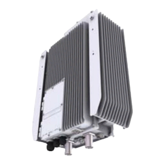
Smart MBS RRH-P4 Installation Manual CHAPTER 1. Before Installation 1.1 System Configuration RRH-C2A Configuration The following shows the configuration of RRH-C2A. [Unit: mm] [Top View] [Left View] [Front View] [Right View] [Rear View] [Bottom View] Figure 1.1 RRH-C2A Configuration © SAMSUNG Electronics Co., Ltd. -
Page 20: Figure 1.2 External Interfaces Of Rrh-C2A
CHAPTER 1. Before Installation External Interfaces of RRH-C2A The following shows the external interfaces of RRH-C2A. POWER [-48 V] OPTIC_1 OPTIC_0 Ground ANT 1 ANT 0 [Bottom View] Figure 1.2 External Interfaces of RRH-C2A © SAMSUNG Electronics Co., Ltd. -
Page 21: Specifications
Size (mm, W × D × H) - 400 ×171 × 598 (with External Filter) - 400 ×171 × 490 (without External Filter) Weight (kg) - 23.5 (with External Filter) - 21 (without External Filter) © SAMSUNG Electronics Co., Ltd. - Page 22 (EMC) US Federal Regulation FCC Title47 Part90 a) Temperature and humidity are measured at 1.5 m (59 in) above the floor and at 400 mm (15.8 in) away from the front panel of the RRH-C2A. © SAMSUNG Electronics Co., Ltd.
-
Page 23: Cabling
6) RET Cable 7) RF Cable [MGB] 1) MGB Ground Cable [TGB] 2) TGB Ground Cable ※ TGB and Ground Kit are used in case of the 7/8 in. feeder line or more. Figure 1.3 Cabling Diagram © SAMSUNG Electronics Co., Ltd. -
Page 24: Table 1.1 System Cabling
: AWG10, 4 mm × 2C(or AWG8,6 mm × 2C) UADU 5) CPRI Cable : Optic Cable (Single Mode) 6) RET Cable Ass’y (Shield Cable) Antenna 7) RF Cable (1/2 in. or 7/8 in. Feeder Line) © SAMSUNG Electronics Co., Ltd. -
Page 25: Installation Precaution
Watches, Rings, and Other Metallic Accessories Do not wear accessories such as watches and rings in order to prevent electrical shock. Do not work by yourself Do not work by yourself in any key process. © SAMSUNG Electronics Co., Ltd. - Page 26 Always use the maximum curvature radius possible, and make sure that the minimum curvature radius specification is complied with. If the cable needs to be protected, use a PVC channel, spiral sleeve, flexible pipe, and cable rack, etc. © SAMSUNG Electronics Co., Ltd.
-
Page 27: Table 1.2 Allowed Cable Bend Radius
And insert the remaining string into the knot and make sure the knot does not loosen. If there is a potential danger of contact failure in a connector connection due to tension, install the cable in the shortest distance. © SAMSUNG Electronics Co., Ltd. - Page 28 Install the DC power cable and data transmission cable away from the AC power cable to prevent electromagnetic induction. Cable Works The cable works require knowledge for the cabling works such as cable installation/binding. © SAMSUNG Electronics Co., Ltd. 1-10...
- Page 29 The board should be kept away from materials prone to static electricity such as plastic, acrylic plates, paper, Styrofoam etc. The board should be kept in a static electricity prevention storage box. © SAMSUNG Electronics Co., Ltd. 1-11...
-
Page 30: Pre-Construction Inspection
The status of the external interface The status of the power capacity and its wiring The extendibility of the system Whether the site has sufficient space for operation and maintenance © SAMSUNG Electronics Co., Ltd. 1-12... -
Page 31: Installation Tool
The required installation tools may vary depending on the conditions at the site. In addition to the basic tools, a protractor, compass, GPS, ladder, safety equipment, cleaning tools etc. should also be prepared in consideration of the site conditions. © SAMSUNG Electronics Co., Ltd. 1-13... - Page 32 CHAPTER 1. Before Installation This page is intentionally left blank. © SAMSUNG Electronics Co., Ltd. 1-14...
-
Page 33: Chapter 2. Installation Of Rrh-C2A
* This procedure may be omitted when using an existing installation. If required, additional work can be done through the standard procedure, and thus will not be described in this manual. Figure 2.1 System Installation & Cable Connection Procedure © SAMSUNG Electronics Co., Ltd. -
Page 34: Foundation Work
Figure 2.2 RRH-C2A Installation Space (1 sector pole type) Equipment Installation Space The figure above illustrates the installation space using a 101.6 mm(90 A) diameter pole. The measures may differ depending on the diameter of the pole. © SAMSUNG Electronics Co., Ltd. -
Page 35: Unpacking And Transporting
Unpack the inner packaging after each system is placed on its installation location. Unpack the inner packaging after each system is placed on its installation location. Do not recycle the packaging waste. Dispose of them pursuant to the rules. © SAMSUNG Electronics Co., Ltd. -
Page 36: Fixing The System
를 사용하여 RRH mounting Bracket-L/R 을 견고하게 고정한다. M12 Strong Anchor Bakelite RRH Mounting Bracket-L RRH Mounting Bracket-R M12 Insulation Bushing M12 Plane Washer M12 Spring Washer M12 Hex. Bolt Figure 2.3 Fixing Wall Mount (1) © SAMSUNG Electronics Co., Ltd. -
Page 37: Figure 2.4 Fixing Wall Mount (2)
남도록 하여 임시로 고정한다. M8 x 25L Hex. Nut M8 Spring Washer M8 Plane Washer RRH-C2A M12 Plane Washer M12 Spring Washer M12 x 25L Hex. Bolt ≒ 6 mm Figure 2.4 Fixing Wall Mount (2) © SAMSUNG Electronics Co., Ltd. - Page 38 The fasteners used to attach the wall mount, including the anchor bolt, spring washer, plane washer and Hex. nut must be made of stainless steel (STS 304). Otherwise, it may cause corrosion and rust to fixing materials. © SAMSUNG Electronics Co., Ltd.
-
Page 39: Fixing 1 Sector Pole
M12 x 180L Hex. bolt 에 맞추어 끼운 후 M12 plane washer, spring washer, Hex. nut 를 이용하여 견고하게 고정한다. Pole Pole Mount Bracket M12 Plane Washer M12 Spring Washer M12 Hex. Nut Figure 2.8 Fixing 1 sector pole (1) © SAMSUNG Electronics Co., Ltd. - Page 40 남도록 하여 임시로 고정한다. M8 x 25L Hex. Nut M8 Spring Washer M8 Plane Washer RRH-C2A M12 Plane Washer M12 Spring Washer M12 x 25L Hex. Bolt ≒ 6 mm Figure 2.9 Fixing 1 sector pole (2) © SAMSUNG Electronics Co., Ltd.
- Page 41 The fasteners used to attach the pole, including the hex. bolts, hex. nut, spring washers and plane washers must be made of stainless steel (STS 304). Otherwise, it may cause corrosion and rust to fixing materials. © SAMSUNG Electronics Co., Ltd.
-
Page 42: Connecting Cable Between Rrh And Antenna
Caution for connecting Feeder Line Connector When connecting the feeder line between RRH-C2A RF port and RF antenna, each port and the feeder line connector should be secured by 200 kgf.cm torque to minimize influence of PIMD. © SAMSUNG Electronics Co., Ltd. 2-10... -
Page 43: Figure 2.8 Connecting Rrh-C2A Feeder Line (1)
3) After installing the connector, shrink the heat shrink tubes using a heat gun. Detail ‘A’ Din-Type Male Connector 1/2 in. Feeder Line Heat Shrink Tube (Jelly Type) Figure 2.8 Connecting RRH-C2A Feeder Line (1) © SAMSUNG Electronics Co., Ltd. 2-11... -
Page 44: Figure 2.9 Connecting Rrh-C2A Feeder Line (2)
Caution for connecting Feeder Line Connector When connecting the feeder line between RRH-C2A RF port and RF antenna, each port and the feeder line connector should be secured by 200 kgf.cm torque to minimize influence of PIMD. © SAMSUNG Electronics Co., Ltd. 2-12... - Page 45 Antenna Protection Plate Antenna Jumper Cable (1/2 in. Feeder Line) Heat Shrink Tube (Jelly Type) Heat Shrink Tube (Jelly Type) 3) Avoid aiming the heating gun toward the antenna’s body as shown in the figure below. © SAMSUNG Electronics Co., Ltd. 2-13...
-
Page 46: Table 2.2 Gps Identification Tag Of Feeder Line
Fixing method Fix the feeder cable to the 2 holes on the identification tag with the black cable tie. Marking The markings must be prevented from being erased by using relief engraving or coated labels. © SAMSUNG Electronics Co., Ltd. 2-14... -
Page 47: Connecting Ret Cable
Follow the steps below to connect the Remote Electrical Tilting (RET) cable used to control the tilting angle of the antenna from the distance. RET Connector (SAMWOO, SU-20SP-8P) RET Cable (Shield Cable) Heat Shrink Tube (Jelly Type, Black) Figure 2.10 Connecting RET cable © SAMSUNG Electronics Co., Ltd. 2-15... -
Page 48: Figure 2.11 Ret Cable Connector
- When 28 VDC volts are applied, the current supplied to the RET from RRH-C2A must be lower than 1 A. - The exterior of the RET connector must be made of metal without vent hole or other UL certified material. © SAMSUNG Electronics Co., Ltd. 2-16... -
Page 49: Connecting Ground Cable
(2Hole, 90°, Hole diameter: 6.3 mm, Hole distance: 16 mm) Detail ‘A’ Heat Shrink Tube(Green) M6 x 12L SEMS Ground Cable(AWG8, GV 6 mm × 1C) From MGB(Main Ground Bar) Figure 2.12 Connecting RRH-C2A Ground cable © SAMSUNG Electronics Co., Ltd. 2-17... - Page 50 Check the position of the coaxial cable through the inspection window of the pressure terminal before compressing it with a compressor. © SAMSUNG Electronics Co., Ltd. 2-18...
-
Page 51: Connecting Hybrid Cable
B) Hold both ends of the hybrid cable and lift it out of the box. Tape the power cable and optic cable separately at 1 m interval. Also, tape the exposed optic connector to prevent damage. Tape Figure 2.13 Installing Hybrid cable (1) © SAMSUNG Electronics Co., Ltd. 2-19... -
Page 52: Figure 2.14 Installing Hybrid Cable (2)
C) Take the cable out of the box paying attention not to impact the junction box and the jumper cable. Be careful not to drag the jumper cable on the floor. Jumper Cable Junction Box D) Lay the hybrid cable on the floor. Figure 2.14 Installing Hybrid cable (2) © SAMSUNG Electronics Co., Ltd. 2-20... -
Page 53: Figure 2.15 Installing Hybrid Cable (3)
Wind the pulling wire by 7 times or more to the 1 m or more length of hybrid cable. Min. 1 m Pulling Wire Junction Box (Breakout Point) Min. 1 m Figure 2.15 Installing Hybrid cable (3) © SAMSUNG Electronics Co., Ltd. 2-21... -
Page 54: Figure 2.16 Installing Hybrid Cable (4)
Pulling Wire Junction Box (Breakout Point) Hoisting Wire Max. 1 m Max. 1 m Hybrid Cable More than 150 mm Max. 1 m Hoisting Wire Figure 2.16 Installing Hybrid cable (4) © SAMSUNG Electronics Co., Ltd. 2-22... -
Page 55: Connecting Du Cabinet Side Cable
7) Unsheathe the end of the power cable wire at 15 mm. 8) Using a conduit, insert the hybrid cable’s power cable and optic cable together into the cabinet. Be careful not to damage the optic cable’s connector. © SAMSUNG Electronics Co., Ltd. 2-23... -
Page 56: Figure 2.17 Peeling Off The Hybrid Cable Sheath
Hybrid Cable Sheath 3) Peel off the hybrid cable’s sheath. 4) Peel off the aluminum foil wrapped around the inner cable. Figure 2.17 Peeling off the Hybrid Cable Sheath © SAMSUNG Electronics Co., Ltd. 2-24... -
Page 57: Figure 2.18 Connecting Hybrid Cable (1)
Double-layer Sheath Peel-off Point RRH Power Terminal Flexible Pipe (2 in.) Max. 1,000 mm DC Power Cable Butyl Rubber Tape Hybrid Cable 600 mm [Baseband Rack Right View] Figure 2.18 Connecting Hybrid cable (1) © SAMSUNG Electronics Co., Ltd. 2-25... -
Page 58: Figure 2.19 Connecting Hybrid Cable (2)
Table 2.4 Hybrid Cable Color Map Group 0 Group 1 Group 2 Group 3 (1.9 GHz) (800 MHz) (2.5 GHz) (2.5 GHz) Return White/Red stripe White/Black stripe White/Blue stripe White/Brown stripe -48 V Black Blue Brown © SAMSUNG Electronics Co., Ltd. 2-26... -
Page 59: Figure 2.20 Connecting Hybrid Cable (3)
Figure 2.20 Connecting Hybrid cable (3) L9CA-B4T_#2 L3~5 Port RRH Interface Connector (LC/PC) RRH Interface(CPRI) Cable (Hybrid Cable) Space for the remainder of RRH CPRI Cable [CPRI Cable Connection] Figure 2.21 Connecting Hybrid cable (4) © SAMSUNG Electronics Co., Ltd. 2-27... - Page 60 - Unused cable insertion hole: Finish cable insertion hole using fishing materials such as dust cap, rubber packing and etc. - Cable-installed insertion hole: After installing cable, finish insertion hole using tape, compressed sponge, rubber packing, silicon, etc. to prevent empty space. © SAMSUNG Electronics Co., Ltd. 2-28...
-
Page 61: Connecting Rrh-C2A Power Cable
1) Unscrew the power window cover fixing screw located at the rear bottom of RRH- C2A using a Torx (T20) screwdriver. (The cover fixing screw is designed to remain attached to the cover.) Cover Fixing Screw(T20) Install Window Cover Figure 2.22 Connecting RRH-C2A power cable (1) © SAMSUNG Electronics Co., Ltd. 2-29... -
Page 62: Figure 2.24 Connecting Rrh-C2A Power Cable (Awg8) (3)
When cutting the cable first, the length difference of cable end can be occurred by cable curvature and the power terminal may cause contact fault. © SAMSUNG Electronics Co., Ltd. 2-30... - Page 63 So, clamp of the bottom must be moved down completely. 9) Inset power cable(Sheath is stripped) with the correct polarity, fasten the screw by torque 14 kgf.cm.(Refer to the 'Caution for connecting power cable to terminal block') © SAMSUNG Electronics Co., Ltd. 2-31...
-
Page 64: Figure 2.25 Connecting Rrh-C2A Power Cable (Awg8) (4)
Power Cable (-48V:Black, RTN:White/Black strip) Bracket Fixing Screw (Torque: Max. 5.1 kgf.cm) Power Cable Bracket -48V Heat Shrink Tube (-48V:Blue, RTN:Red) 5 mm Power Cable Bracket Figure 2.25 Connecting RRH-C2A power cable (AWG8) (4) © SAMSUNG Electronics Co., Ltd. 2-32... - Page 65 Installing the Circuit Breaker To ensure stability in power supply, a circuit breaker must be installed on the power cable connected to the rectifier (or power distributor). Capacity of -48 VDC circuit breaker is 32 A. © SAMSUNG Electronics Co., Ltd. 2-33...
-
Page 66: Connecting Rrh-C2A Cpri Cable
1) Unscrew the optic window cover fixing screw located at the front bottom of RRH-C2A using a Torx (T20) screwdriver. (The cover fixing screw is designed to remain attached to the cover.) Cover Fixing Screw(T20) Install Window Cover Figure 2.34 Connecting RRH-C2A CPRI cable (1) © SAMSUNG Electronics Co., Ltd. 2-34... - Page 67 40.8 kgf.cm. 6) When the CPRI cable connection is complete, close the window cover and fasten the screw by torque: 12.0 kgf.cm. © SAMSUNG Electronics Co., Ltd. 2-35...
-
Page 68: Figure 2.35 Connecting Rrh-C2A Cpri Cable (2)
Figure 2.35 Connecting RRH-C2A CPRI cable (2) Optic1 (CDMA0) Table 2.5 CPRI Cable connection configuration Cable Color Blue Orange Green Brown Gray Port Optic 0 (LTE 0) Optic 1 (CDMA 0) Spare Spare Spare Optic Cable (Single Mode) © SAMSUNG Electronics Co., Ltd. 2-36... - Page 69 CDMA UADU(Installed in DU cabinet). Connect the optic cable(Refer to the connection standard of 'table 2.6' and 'table 2.7'). Because false connection can cause the fault of call connection, be cautious. © SAMSUNG Electronics Co., Ltd. 2-37...
-
Page 70: Remaining Length Of Hybrid Cable
2) Bind the power cable and CPRI cable together with the feeder line using a cable tie. Feeder Line RRH-C2A RRH-C2A Fixing Pole Cable Tie Cable Tie Cable Tie Remaining length of cable Figure 2.36 Remaining length of Hybrid cable (1) © SAMSUNG Electronics Co., Ltd. 2-38... -
Page 71: Figure 2.37 Remaining Length Of Hybrid Cable (2)
Power & Optic Cable (to. RRH-C2A) 500 mm Stainless steel Band Junction Box Pole (Breakout Point) Stainless steel Band 500 mm Hybrid Cable (from. DU Cabinet) Cable Tie Figure 2.37 Remaining length of Hybrid cable (2) © SAMSUNG Electronics Co., Ltd. 2-39... -
Page 72: Figure 2.38 Remaining Length Of Hybrid Cable (3)
4) Bind the spare cable to the pole with its waterproof cap facing up. Loop the cable’s remaining length and bind it to the pole below the cap. Cable Tie Water proof Cap Pole Cable Tie Cable 여장 Figure 2.38 Remaining length of Hybrid cable (3) © SAMSUNG Electronics Co., Ltd. 2-40... -
Page 73: Installation Test
Verify that the LED(Red or green) in the RRH-C2A installation window is lit. 5) Fasten the cover fixing screw (T20) using a Torque 12.0 kgf.cm. Close the power window cover and the optic window cover. © SAMSUNG Electronics Co., Ltd. 2-41... -
Page 74: Table 2.8 Construction Status Checklist
Optic Cabling Status Visual inspection interface Ground Ground line standard Visual inspection Construction Ground bar ↔ System Visual inspection Ground line cabling Cabling status check status Termination treatment of Visual inspection the ground line (Pressure Terminal) © SAMSUNG Electronics Co., Ltd. 2-42... - Page 75 Cable duct, bolt connection Visual inspection status Feeder line Entrance end Visual inspection processing status (Outdoor) (Checking back side Connection) Status of inside/outside of Visual inspection the system and vicinity of the base station General Opinion © SAMSUNG Electronics Co., Ltd. 2-43...
-
Page 77: Annex A. Sector Antenna Installation
In the event of the station whose the direction between sectors is not 120°, install it to make the steel tower and antenna direction different being careful of the tilt and azimuth. 4) For circular platform, separate the antenna interval at maximum. © SAMSUNG Electronics Co., Ltd. -
Page 78: Sector Antenna Installation
Guide Clamp Bolt_3 Guide Clamp Bolt_1 Upper Fixing Clamp Upper Guide Clamp Guide Clamp Bolt_2 Pole Main Radiation Direction Lower Guide Clamp Lower Fixing Clamp Antenna Input Port Guide Clamp Bolt_4 Figure A.1 Sector Antenna © SAMSUNG Electronics Co., Ltd. - Page 80 500cm during normal operation. The gain of the antenna is 14 dBi. The antenna(s) used for this transmitter must not be co-located or operating in conjunction with any other antenna or transmitter. ⓒ SAMSUNG Electronics Co., Ltd.