Advertisement
Quick Links
Advertisement

Related Manuals for NCR TPM 2.0 Security Chip


Summary of Contents for NCR TPM 2.0 Security Chip
- Page 1 KIT INSTRUCTIONS TPM 2.0 Security Chip Release 1.0 7607–K158 Issue A...
- Page 2 NCR, therefore, reserves the right to change specifications without prior notice. All features, functions, and operations described herein may not be marketed by NCR in all parts of the world. In some instances, photographs are of equipment prototypes. Therefore, before using this document, consult with your NCR representative or NCR office for information that is applicable and current.
-
Page 3: Revision Record
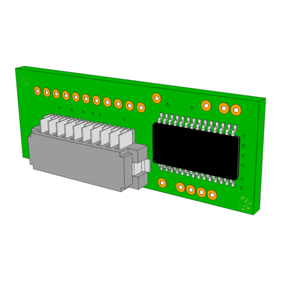
Revision Record Issue Date Remarks Nov 2016 First Issue... - Page 4 TPM 2.0 Security Chip Introduction This kit provides a TPM 2.0 Security Chip for the RealPOS XR7 Plus POS.
-
Page 5: Installation Procedure
TPM 2.0 Security Chip Installation Procedure 1. Lay the terminal face down on a flat surface. Caution: Always use a soft material (cloth, foam) to protect the display screen when placing the terminal face down. 2. Remove the Base Stand. - Page 6 TPM 2.0 Security Chip 3. Remove the Rear Cover assembly. a. Remove the Cable Cover. b. Loosen the captive screws (2) that secure the Rear Cover to the chassis. c. Pivot the assembly as shown to remove it.
- Page 7 TPM 2.0 Security Chip 4. Connect the TPM Board to the Motherboard.