NCR 7705 Kit Instructions
Sidecar upgrade full configuration
Hide thumbs
Also See for 7705:
- Kit instructions (8 pages) ,
- Operator's manual (127 pages) ,
- Hardware installation manual (120 pages)
Advertisement
Quick Links
Advertisement

Related Manuals for NCR 7705


Summary of Contents for NCR 7705
- Page 1 Kit Instructions 7705 Sidecar Upgrade (Full Configuration) 7705-K051 Issue A...
-
Page 2: Revision Record
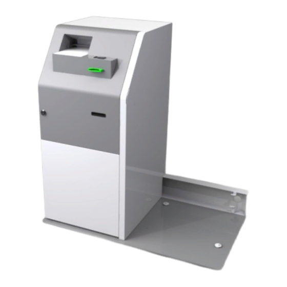
NCR, therefore, reserves the right to change specifications without prior notice. All features, functions, and operations described herein may not be marketed by NCR in all parts of the world. In some instances, photographs are of equipment prototypes. Therefore, before using this document, consult with your NCR representative or NCR office for information that is applicable and current. - Page 3 7705 Sidecar Upgrade (Full Configuration) Introduction This kit provides a Sidecar with the following features to the NCR SelfServ™ 75 (7705) Kiosk: • SIM Card Dispense • Fingerprint Reading • ID Card Reading • Passport Reading The SelfServ 75 Kiosk with Sidecar configuration is freestanding and does not require to...
-
Page 4: Kit Contents
7705 Sidecar Upgrade (Full Configuration) Kit Contents... - Page 5 7705 Sidecar Upgrade (Full Configuration)
- Page 6 7705 Sidecar Upgrade (Full Configuration)
-
Page 7: Tools Required
7705 Sidecar Upgrade (Full Configuration) Tools Required When installing the Kiosk to the Sidecar, it is recommended that you have the following items available: • Pincers/claw hammer to remove staples/nails from around the pallet • Scissors • Selection of screwdrivers (flat, Pozi and cross head) •... -
Page 8: Installation Procedure
Avoid any contact with internal parts and handle cards only by their external edges. The 7705 with Sidecar is freestanding and does not require to be bolted to the floor. To install the Sidecar to the Main Kiosk Cabinet, perform the procedures below. - Page 9 7705 Sidecar Upgrade (Full Configuration) Removing the External Packaging Before removing the external packaging, examine it for signs of damage which may have occurred during transit. Make a note of any external damage. Note: Take care not to damage the Sidecar when removing the packaging.
- Page 10 7705 Sidecar Upgrade (Full Configuration) Removing the Sidecar from its Pallet 1. Underneath the right-hand side of the pallet, remove the screws (3) securing the pallet jack block and then remove the block. 2. Remove the screws (3) securing the brace board and then remove the brace board.
- Page 11 7705 Sidecar Upgrade (Full Configuration) 3. From the underside of the pallet, use a 17 mm (11/16 in.) spanner and socket to remove the shipping bolts (6) securing the Sidecar to the pallet. The illustration below shows the Top View of the Sidecar on the Pallet with the locations of the shipping bolts.
- Page 12 7705 Sidecar Upgrade (Full Configuration) 5. While supporting the Kiosk on both sides, lift the pallet up using a pallet jack and remove the foot from underneath the pallet. 6. Support the Sidecar on both sides and lower the pallet carefully. The pallet tilts to the side where the foot was removed.
- Page 13 7705 Sidecar Upgrade (Full Configuration) Removing the Sidecar Cable Cover 1. Insert the Sidecar Key to the lock. 2. Turn and hold the key to the clockwise position, then slightly tilt the top side of the Sidecar Door forward to unlock the door.
- Page 14 7705 Sidecar Upgrade (Full Configuration) 4. Slide the Cover Panel upward to unhook it and then pull it away from the Sidecar cabinet. 5. Inside the Sidecar Cabinet, remove the wing nuts (2) securing the cover to the cabinet.
- Page 15 7705 Sidecar Upgrade (Full Configuration) 6. Slide the cable cover out of the Sidecar Cabinet.
- Page 16 7705 Sidecar Upgrade (Full Configuration) Mounting the Kiosk on the Sidecar Baseplate 1. Mount the Kiosk on the Sidecar Base Plate. • Make sure that the Kiosk is as close as possible to the Sidecar. • Make sure that the back of the Kiosk aligns with the vertical edge of the Sidecar...
- Page 17 7705 Sidecar Upgrade (Full Configuration) 2. Open the Kiosk Security Enclosure and check that the Kiosk bolt holes (2) align with the holes on the baseplate. If the holes are not aligned, adjust the Kiosk to align the holes. 3. Once the Kiosk and Baseplate holes are aligned, secure the Kiosk to the baseplate using M6x12 Cap Screws (2) and Mounting Fillers (2) through the holes on the front–left corner and rear–right corner.
- Page 18 7705 Sidecar Upgrade (Full Configuration) 4. Inside the Sidecar, remove the tapes securing the following cables and route the cables out of the Sidecar Cabinet through the Cable Entry Hole. Secure the Cables using the P-Loop Cable Clamps along their route.
- Page 19 7705 Sidecar Upgrade (Full Configuration) Connecting the DC Distribution Cable to the Sidecar 1. Connect the 497-0520823 DC Distribution Cable to one of the Sidecar DC Hub ports. 2. Route the DC cable out of the Sidecar cabinet through the cable entry hole and secure the cable using cable clamps along its route.
- Page 20 7705 Sidecar Upgrade (Full Configuration) Connecting AC Power Cables to the Sidecar Power Strip There are three AC cables provided in this kit to connect the Sidecar and Main Kiosk.These are taped inside the Sidecar Cabinet. The cables that will be used depends on the presence of a UPS and the Kiosk Vac rating.
- Page 21 7705 Sidecar Upgrade (Full Configuration) 220V Kiosk with UPS A 220V Kiosk with UPS uses one of the 497-0415086 IEC cables included in this kit. 1. Connect the 497-0415086 IEC cable to the Power Strip Inlet. 2. Route the cable out of the Sidecar cabinet through the cable entry hole.
- Page 22 7705 Sidecar Upgrade (Full Configuration) Kiosk without UPS A Kiosk without UPS configuration uses the two 497-0415086 IEC cables provided in this kit. 1. Connect one of the 497-0415086 IEC cable to the Power Strip inlet. 2. Connect the second 497-0415086 IEC cable to one of the Power Strip outlets.
- Page 23 7705 Sidecar Upgrade (Full Configuration) Routing the Sidecar Cables into the Main Kiosk 1. Route the following cables from the Sidecar into the Kiosk Cabinet through the cable entry hole: • sidecar USB cable (009-0020710) • ground cable (497-0456662) • AC power cable (497-0415086 or 497-0474546) Note: If there is no UPS in the Kiosk, there are two 497-0415086 cables from the Sidecar, one connected to the Power Strip Inlet and the other connected to the...
- Page 24 7705 Sidecar Upgrade (Full Configuration) 2. Mount and secure the cable cover to the Kiosk and Sidecar. a. Insert the Cable Cover hooks into the Kiosk Cable Entry hole, and then slide the cover into the Sidecar. b. Inside the Sidecar, secure the Cable Cover with wing nuts (2).
- Page 25 7705 Sidecar Upgrade (Full Configuration) 3. Inside the Kiosk Security Enclosure, secure the Sidecar Ground cable to the rear-right Vertical Metal frame using a screw (1). 4. Route the Sidecar USB cable upward towards the Top Box I/O Panel.
- Page 26 7705 Sidecar Upgrade (Full Configuration) Connecting the DC Distribution Cable to the Power Supply 1. From the Safe Cable Entry Hole, route the DC Distribution cable to the PSU Ports on the front left-hand side of the Safe. 2. Remove the PSU Bracket. a. Remove the DC cables from the round slot of the PSU Bracket.
- Page 27 7705 Sidecar Upgrade (Full Configuration) c. Carefully slide the bracket forward until clear from the screws and then remove the bracket. Ensure that the cables do not block and do not get pinched when removing the bracket.
- Page 28 7705 Sidecar Upgrade (Full Configuration) 3. Connect the Sidecar DC Distribution Cable to one of the 2-pin ports of the PSU. From the bottom of the safe, route the cable upward behind the PSU and then loop the cable toward the PSU port.
- Page 29 7705 Sidecar Upgrade (Full Configuration) 4. Align the PSU Bracket to the PSU and then insert the bracket to the partially mounted screws. • Ensure that the cables are not pinched and are not blocking the bracket during insertion. • Ensure that the PSU sits within the bracket stoppers for proper mounting...
- Page 30 7705 Sidecar Upgrade (Full Configuration) 5. To secure the cables, insert the cables into the round slot of the bracket. Note: Ensure that the cables do not obstruct the Metal Slide when pulling the Cash Accceptor tray in and out. If necessary, insert the cable loops behind the Metal Slide.
- Page 31 7705 Sidecar Upgrade (Full Configuration) Connecting the Sidecar AC Power Cables to the Main Kiosk The Sidecar AC Power Cable connection to the main Kiosk differs according to the presence of an UPS. Refer to the appropriate procedure below to connect the AC power cables.
- Page 32 7705 Sidecar Upgrade (Full Configuration) 2. Loosen the two screws securing the UPS front bracket to the safe and then remove the bracket. 3. Connect the AC power cable from the Sidecar to the vacant Outlet Port on the UPS. 4. Mount the UPS brackets on the UPS, and then tighten the screws (2 on each bracket)
- Page 33 7705 Sidecar Upgrade (Full Configuration) Kiosk without UPS There are two AC Cables (497-0415086) from the Sidecar, one connected to the Power Strip inlet and one to the Power Strip outlet. 1. Connect the AC cable from the Power Strip outlet to the Kiosk AC filter.
- Page 34 7705 Sidecar Upgrade (Full Configuration) Installing the USB Hub and Cable Strain Relief Caution: Static Electricity Discharge may permanently damage your system. Discharge any static electricity build up in your body by touching the metal cabinet of the Kiosk for a few seconds. Avoid any contact with internal parts and handle cards only by their external edges.
- Page 35 7705 Sidecar Upgrade (Full Configuration) 3. Remove the nut (1)securing the Fascia Harness to the I/O Panel. 4. Loosen the nuts (3) securing the I/O Panel to the cabinet. 5. Slide the I/O Panel assembly upward and pull it away from the cabinet.
- Page 36 7705 Sidecar Upgrade (Full Configuration) 6. Mount the Cable Strain Relief to the I/O Panel and secure it using screws (2) on the rear side of the panel.
- Page 37 7705 Sidecar Upgrade (Full Configuration) 7. Install the 2nd Top Box USB Hub above the existing USB Hub in the I/O Panel. a. Insert the left edge of the board between the bridge lances on the left- hand side and align the mounting holes on the right-hand side.
- Page 38 7705 Sidecar Upgrade (Full Configuration) 8. Connect the DC Distribution Cable (009-0020734) included in this kit to the Top USB Hub and to the right-hand DC Hub. 9. Connect the Mini B connector of the USB A to Mini B cable (009-0020700) included in this kit to the top USB Hub then connect the A connector to the bottom USB Hub.
- Page 39 7705 Sidecar Upgrade (Full Configuration) 10. Mount the I/O Panel assembly back to the cabinet and tighten the nuts (3) to secure the panel. 11. Secure the Fascia harness to the I/O Panel using a nut and route the DVD SATA cable over the MIDI MISC I/F board.
- Page 40 7705 Sidecar Upgrade (Full Configuration) 12. Connect the DC Distribution Cables to the MINI DC Hubs in the I/O Panel. a. Connect a DC Distribution Cable (1) from the 24V PSU to one of the DC Hubs. b. Connect the second DC Distribution Cable (1) from the 24V PSU to the other...
- Page 41 7705 Sidecar Upgrade (Full Configuration) c. Connect the following DC Cables to the left-hand DC Hub: • 12V Regulator if present • 5V Regulator • Cash Dispenser d. Connect the following DC cables to the right-hand DC Hub: • Note Acceptor • Check Acceptor •...
- Page 42 7705 Sidecar Upgrade (Full Configuration) 13. Connect the following USB Cables to the bottom USB HUB, use the cable strain relief to secure the cables: • EBox Mini -B USB • Fujitsu F53 Dispenser • Receipt Printer • Check Acceptor • UPS...
- Page 43 7705 Sidecar Upgrade (Full Configuration) 14. Connect the following USB Cables to the top USB HUB, use the cable strain relief to secure the cables. • Sidecar USB Cable • UX 300 MSR if present...
- Page 44 7705 Sidecar Upgrade (Full Configuration) 15. Connect the following Cables to the MISC I/F, board.Secure and tidy up the cables using cable ties as necessary. • Line-In audio jack • Speaker-Out • ADA Private Audio • Note Dispenser MEI • Auto Supervisor Switch...
- Page 45 7705 Sidecar Upgrade (Full Configuration) 16. Tidy up and bundle theI/O Panel cables using cable ties as necessary to secure them.
- Page 46 7705 Sidecar Upgrade (Full Configuration) 17. Mount the I/O Panel Cover and tighten the screw (1) on the panel to secure the cover. Make sure that the cover does not snag or pinch the cables in or near the panel.
- Page 47 7705 Sidecar Upgrade (Full Configuration) Loading the Card Dispenser Hoppers The Card Dispenser Hoppers can store the following number pieces of cards: Card Types Triple-Hopper Single-Hopper Embossed Cards up to 100 cards up to 100 cards 0.76 mm thick flat cards...
- Page 48 7705 Sidecar Upgrade (Full Configuration) 2. Open the Card Hopper. Lift the Green latch to unlock the cover then rotate the cover forward. 3. Lift the card stack weight from the Hopper.
- Page 49 7705 Sidecar Upgrade (Full Configuration) 4. Load new cards into the hopper. • Magnetic cards—the magnetic stripe must be facing downwards and on the right-hand side (when viewing the dispenser from the front) • SIM cards— the IC chip must be facing upwards and on the rear side of the card 5.
- Page 50 7705 Sidecar Upgrade (Full Configuration) Turning ON the Kiosk The Kiosk should be switched ON using the power switch located in the top-box. 1. Plug the Main AC power cable to an AC power source. 2. If present, push the UPS Power Switch to turn it ON.