Advertisement
Quick Links
INSTALLATION AND MAINTENANCE INSTRuCTIONS
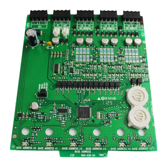
MMF-302-6 Six Zone Interface Module
SPECIFICATIONS
Normal Operating Voltage:
Stand-By Current:
Alarm Current:
Temperature Range:
Humidity:
Dimensions:
Accessories:
Wire Gauge:
Maximum IDC Wiring Resistance:
External Power Supply Voltage:
Ripple Voltage:
IDC (supervised and power limited)
DC Voltage:
Frequency:
Current:
BEFORE INSTALLING
This information is included as a quick reference installation guide. Refer to
the appropriate Fire•Lite control panel installation manual for detailed sys-
tem information. If the modules will be installed in an existing operational
system, inform the operator and local authority that the system will be tempo-
rarily out of service. Disconnect the power to the control panel before install-
ing the modules. This system contains static sensitive components. Always
ground yourself with a proper wrist strap before handling any circuits so that
static charges are removed from the body. The module housing should also
be grounded.
NOTICE: This manual should be left with the owner/user of the equipment.
COMPATIBLE TwO-wIRE SySTEM SENSOR SMOkE DETECTORS FOR uSE wITh MMF-302-6 wITh ZONE A IDENTIFIER
DET.
MODEL
1451DH
2451TH
** 2100AT
2100B
2100D
2100S
2100TB
2100TD
2100TS
2300B
2300TB
2400TH
* 2W-B
* 2W-TB
DH100LP
* Class B, Style B Only
** No Accessory will be supported by 2100AT
F200-22-00
15-32 VDC
2 mA
40 mA (assumes all six LEDs solid on)
32°F to 120°F (0°C to 49°C)
10 to 93% Non-condensing
6.8˝H x 5.8˝W x 1.25˝D
CH-6 Chassis; BB-6 Cabinet; BB-2 Cabinet
12-18 AWG
25 Ohms
Regulated 24VDC
0.1 volts RMS maximum
18-28 volts power limited
DC
90mA per circuit
DETECTOR
COMP. ID
MANUFACTURER
1151
A
SYSTEM SENSOR
1451
A
SYSTEM SENSOR
A
SYSTEM SENSOR
2151
A
SYSTEM SENSOR
2451
A
SYSTEM SENSOR
A
SYSTEM SENSOR
5451
A
SYSTEM SENSOR
1100
A
SYSTEM SENSOR
1400
A
SYSTEM SENSOR
A
SYSTEM SENSOR
A
SYSTEM SENSOR
A
SYSTEM SENSOR
A
SYSTEM SENSOR
A
SYSTEM SENSOR
A
SYSTEM SENSOR
A
SYSTEM SENSOR
A
SYSTEM SENSOR
A
SYSTEM SENSOR
2400
A
SYSTEM SENSOR
A
SYSTEM SENSOR
A
SYSTEM SENSOR
A
SYSTEM SENSOR
A
SYSTEM SENSOR
firealarmresources.com
GENERAL DESCRIPTION
The MMF-302-6 Six Zone Interface Module is intended for use in an intelli-
gent alarm system. Each module provides an interface between the intelligent
alarm system and a conventional alarm system loop. A common SLC input is
used for all modules, and the initiating device loops share a common super-
visory supply and ground. Otherwise, each monitor operates independently
from the others. Each module has its own unique address.
A pair of rotary code switches is used to set the address of the first module
from 01 to 154. The remaining modules are automatically assigned to the next
five higher addresses. Provisions are included for disabling a maximum of two
unused modules to release the addresses to be used elsewhere. Each mod-
ule also has panel controlled bicolor LED indicators. The panel can cause the
LEDs to blink, latch on, or latch off.
BASE MODEL
B110LP,B401
B401, B401B
DH400
B110LP, B401
DH400, B401B,B401
B401, B401B
B401
N/A
N/A
N/A
N/A
N/A
N/A
N/A
N/A
N/A
N/A
N/A
N/A
N/A
N/A
N/A
N/A
1
One FireLite Place
Northford, CT 06472
Phone: 203.484.7161
MAX DET.
20
20
20
20
20
20
20
20
20
20
20
20
20
20
20
20
20
20
20
20
20
20
20
I56-1900-005
Advertisement

Related Manuals for Honeywell Fire-Lite Alarms MMF-302-6


Summary of Contents for Honeywell Fire-Lite Alarms MMF-302-6
- Page 1 INSTALLATION AND MAINTENANCE INSTRuCTIONS One FireLite Place Northford, CT 06472 MMF-302-6 Six Zone Interface Module Phone: 203.484.7161 SPECIFICATIONS Normal Operating Voltage: 15-32 VDC Stand-By Current: 2 mA Alarm Current: 40 mA (assumes all six LEDs solid on) Temperature Range: 32°F to 120°F (0°C to 49°C) Humidity: 10 to 93% Non-condensing Dimensions:...
-
Page 2: Installation Steps
INCLuDED: INSTALLATION STEPS (5) 1 x 4 Terminal Blocks (2) 11/4˝ Stand offs (3) Shunts Cabinet Mounting In a clean, dry area, mount the backbox using the four holes provided in the back surface of the cabinet (Figure 3). 2. Chassis Installation The CH-6 chassis is mounted in the BB-6 cabinet. -
Page 3: Wiring Notes
The steps in Figures 6a and 6b describe and illustrate module installation In Class B operation, the remaining modules are automatically assigned to the when the rear chassis position and the position in front of it will be filled. next five higher addresses. For example, if the base address switch is set to 28, Front position installation is possible only if the rear position is filled with the next five modules will be addressed to 29, 30, 31, 32 and 33. - Page 4 FIGuRE 8. INTERFACE TwO-wIRE CONvENTIONAL DETECTORS – CLASS B, STyLE B: CONNECT MODULES TO BASE ADDRESS LISTED COMPATIBLE FIRE•LITE CONTROL 6 7 8 9 6 7 8 9 PANELS ONLY 3.9K EOL RESISTOR (INCLUDED) ELR-47K – – CLASS B IDC (TYPICAL) TO PANEL CONTROLLED (–) RESETTABLE POWER SUPPLY...
-
Page 5: Fcc Statement
FIGuRE 10. ExAMPLE OF MuLTIPLE BOARDS ShARING SAME ExTERNAL SuPPLy. REFER TO FIGuRES 8 AND 9 FOR TyPICAL wIRING. MAkE CERTAIN LIP ON LONG POwER SuPPLy juMPER ENGAGES RETAINING TAB ON T5 OR T6 AS ShOwN IN vIEw A-A: PCB 1 PCB 2 —...