Table of Contents
Advertisement
Quick Links
Advertisement
Table of Contents

Related Manuals for Honeywell PRO42R1


Summary of Contents for Honeywell PRO42R1
- Page 1 PRO42R1 INSTALLATION AND SPECIFICATIONS Install Guide...
- Page 2 All product and brand names are the service marks, trademarks, registered trademarks, or registered service marks of their respective owners. Printed in the United States of America. Honeywell reserves the right to change any information in this document at any time without prior notice.
-
Page 3: Table Of Contents
PRO42R1 Hardware ....................... 2 Reader wiring..........................3 Door Strike Relay Wiring ....................... 4 Communication Wiring ......................5 Address Baud Rate and Encryption Configuration Switch ........6 Status LEDs ..........................7 Specifications..........................8 Warranty ............................9 Liability ............................9 PRO42R1 Installation Guide, Document 800-26500... - Page 4 (This page is intensionally left blank) PRO42R1 Installation Guide, Document 800-26500...
-
Page 5: Chapter 1 - Installation And Specification
SPECIFICATION General The PRO42R1 reader interface provides a solution to the OEM system integrator for interfacing to a TTL (D1/D0, Clock/Data), F/2F or RS-485 device, and door hardware. It also provides a tri-stated LED control and buzzer control. Two Form-C contact relay outputs may be used for strike control or alarm signaling. -
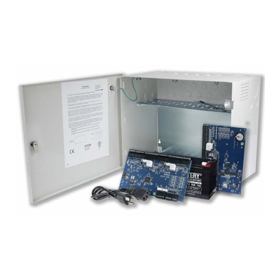
Page 6: Pro42R1 Hardware
PRO42R1 Hardware The PRO42R1 requires filtered 12 to 24 Vdc ± 10% for power. Two inputs are typi- cally used for door contact and exit push button monitoring. End of line resistors are required input supervision, shown below. Note: The input power is passed through to the reader terminal strip and is available for powering a reader. -
Page 7: Reader Wiring
In the 2-wire LED mode the buzzer output is used to drive the sec- ond LED. Reader port configuration is set via the host software. Do not terminate any RS-485 device connected to the reader port. Caution: : D1 to LED on supervised F/2f readers PRO42R1 Installation Guide, Document 800-26500... -
Page 8: Door Strike Relay Wiring
Door Strike Relay Wiring The PRO42R1 has two Form-C contact relays for controlling a door strike or other devices. See specifications section for the relay contact ratings. Load switching can cause abnormal contact wear and premature contact failure. Switching of inductive loads (strike) also causes EMI (electromagnetic interference) which may interfere with normal operation of other equipment. -
Page 9: Communication Wiring
Communication Wiring The PRO42R1 communicates to a Honeywell Security intelligent controller (EP2500 for example) via a half-duplex multi-drop 2-wire RS-485 interface. The total cable length is limited to 4,000 feet (1,219 meters). Shielded cable of 24 AWG with characteristic impedance of 120 ohm is specified for the 2- wire RS-485 inter- face. -
Page 10: Address Baud Rate And Encryption Configuration Switch
Address 17 OFF OFF OFF Address 18 OFF OFF Address 19 OFF ON OFF OFF Address 20 OFF ON OFF ON Address 21 OFF ON OFF Address 22 OFF ON Address 23 OFF OFF Address 24 PRO42R1 Installation Guide, Document 800-26500... -
Page 11: Status Leds
The D1 LED is turned ON at the beginning of initialization Run time: After a successful initialization, the LEDs have the following meanings D1 LED: Heartbeat and On-Line Status Off-line: 1 second rate, 20% ON, 80% OFF PRO42R1 Installation Guide, Document 800-26500... -
Page 12: Specifications
1 twisted pair per input, 30 ohms maximum Outputs: As required for the load Reader data (TTL): 6-conductor, 18 AWG, 500 ft. (150 m) maximum Reader data (F/2F): 4-conductor, 18 AWG, 500 ft. (150 m) maximum PRO42R1 Installation Guide, Document 800-26500... -
Page 13: Warranty
5 to 95 % RHNC Warranty Honeywell Security warrants the product is free from defects in material and work- manship under normal use and service with proper maintenance for one year from the date of factory shipment. Honeywell Security assumes no responsibility for products damaged by improper handling or installation. - Page 14 PRO42R1 Installation Guide, Document 800-26500...
- Page 15 Discover | Customer Portal Self-Service Product Support and Learning Management System https://honeywelldiscovertraining.com/login/discover/default.asp YouTube | Honeywell Help and Support https://www.youtube.com/channel/UCBEL6ouNV_LN5lEpYRujMTg/featured...
- Page 16 Honeywell Integrated Security, 135 W. Forest Hill Avenue Oak Creek, WI 53154 United States 800-323-4576 414-766-1798 Fax www.security.honeywell.com ™ Document 800-26500 11/2020...